SINUMERIK 840D sl. Service - Functions. Manual (2018-2020) - page 65
K9: collision avoidance, internal
7
7.1
Function description
7.1.1
Options
The function "Collision avoidance" is an option that requires a license. The following versions
are available:
● Collision avoidance ECO (machine): 6FC5800-0AS03-0YB0
Properties:
- Protection: Machine - Machine
- HMI visualization
- Only for single-channel control configurations.
- Protection area elements: geometric primitives
● Collision avoidance (machine, working area): 6FC5800-0AS02-0YB0
Properties:
- as for Collision avoidance ECO
- Protection area elements: Files in STL and NPP format
7.1.2
Characteristics
The "Collision avoidance" function is used to prevent collisions of machine parts and tool
cutting edges while the machine axes are being traversed. To do this, the function cyclically
calculates the clearance to the protection areas enveloping the bodies to be protected. If two
protection areas approach one another to within a configurable safety clearance, an alarm is
displayed and the NC program stopped before the relevant traversing block (AUTOMATIC,
MDI mode) or the traversing motion is stopped (JOG mode).
Sequence
The collision avoidance is set up in the following sequence:
1. Release of the "Collision avoidance" function by setting the corresponding option
(Page 273).
2. Setting the machine data for the basic parameterization of the functions:
- Kinematic chain, section "Machine data (Page 197)"
- Geometric machine modeling, section "Machine data (Page 234)"
- Collision avoidance, section "Machine data (Page 285)"
Special functions
Function Manual, 12/2018, A5E40874099B AB
273

K9: collision avoidance, internal
7.1 Function description
3. Writing of the machine kinematic structure through kinematic elements.
See Chapter "K7: Kinematic chain (Page 191)".
4. Writing of the protection areas and protection area elements as enveloping geometry of
the machine parts, tools and workpieces to be protected. Assignment of the protection area
to elements of the kinematic chain.
See Chapter "K8: Geometric machine modeling (Page 225)".
5. Definition of collision pairs, i.e. of two protection areas that are to be monitored for collision.
See Chapter "$NP_COLL_PAIR (Page 288)".
6. Triggering a recalculation of the kinematic and geometric model.
See Chapter "Request recalculation of the machine model of the collision avoidance
(PROTA) (Page 294)".
7. Activation of the protection areas to be monitored.
See Chapter "Setting the protection zone status (PROTS) (Page 295)".
8. Optional: Use of the extended functions and system variables
Limits of the collision avoidance
The function cannot guarantee complete protection against a collision when traversing
machine parts, tools of workpieces. On the one hand, the collision protection can only be as
good as the parameterized kinematic and geometric model or the machine and the protection
areas. On the other hand, bodies that have not been modeled cannot be monitored at all. For
this reason, it remains the responsibility of the machine operator to ensure that a traversing
motion is executed collision-free even when the collision protection is activated.
States of protection areas
Whether a protection area is taken into account for collisions, depends on the state of the
protection area:
State
Meaning
Active
The protection area is taken into account for collisions.
Inactive
The protection area is not taken into account for collisions.
Preactivated
The protection area is taken into account for collisions. A collision alarm is only issued
when it has also been activated by a protection area-specific NC/PLC interface signal.
State after control ramp-up
After the control has powered up, all protection areas are in the state corresponding to their
respective setting in $NP_INIT_STAT. See Section "$NP_INIT_STAT (Page 244)".
State change
The state of a protection areas can be changed by:
● The PROTS() (Page 295) procedure
● Change of the initialization state to $NP_INIT_STAT followed by recalculation of the
machine model through the PROTA() (Page 294)procedure.
Special functions
274
Function Manual, 12/2018, A5E40874099B AB
K9: collision avoidance, internal
7.1 Function description
Requirements
The following requirements must be satisfied so that the protection areas of a collision pair
can be monitored:
● Axes or spindles: referenced/synchronized
The position measurement system for the axes or spindles which move a protection area
must be referenced or synchronized. If this has not been done the corresponding protection
area is in an "inactive" state.
● External motion
With traversing motions that are not performed by the NC, e.g. PLC axis or manually moved
axis, the current axis position must be known in the NC.
7.1.3
Reaction of the control to a risk of collision
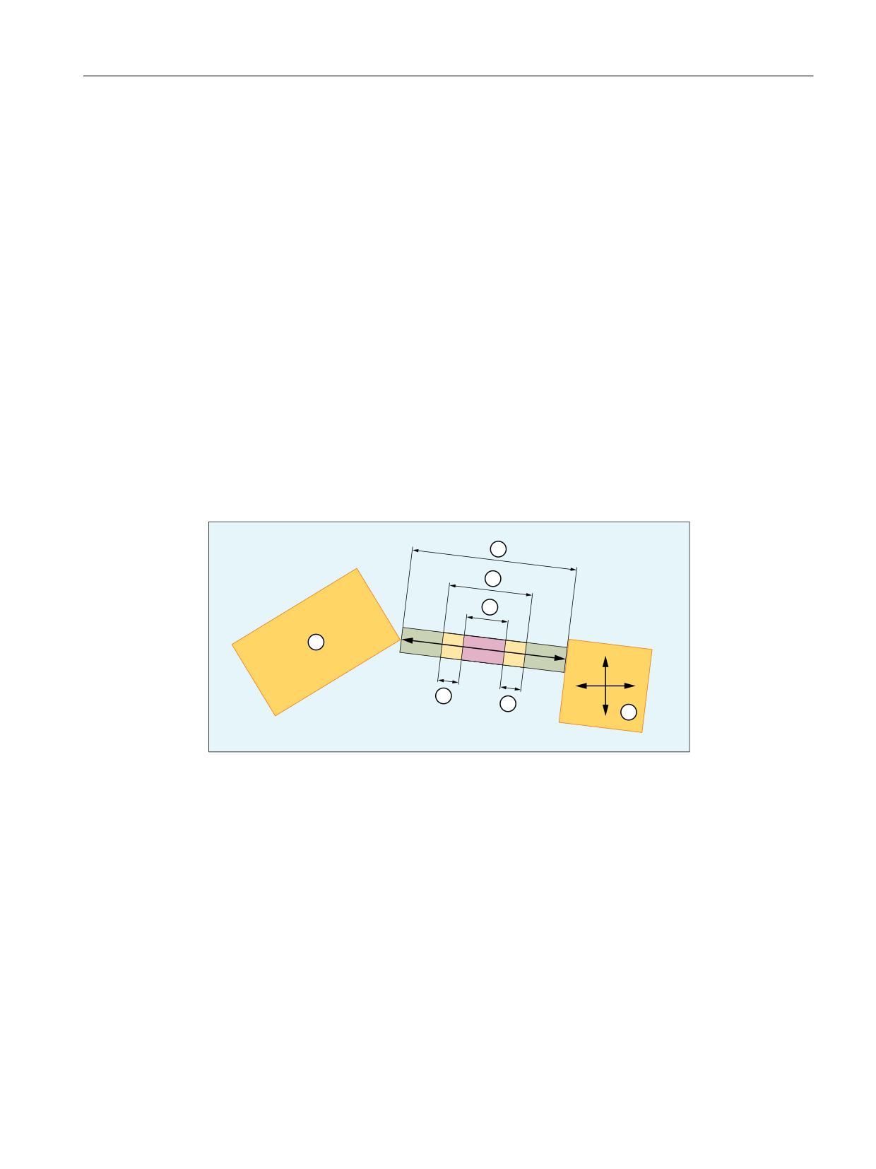
The collision avoidance takes the following parameterizable limit values into account for the
collision detection:
● Collision tolerance
● Safety clearance
<
;
① Protection area 1 (static)
② Protection area 2 (can be moved in X and Y direction)
③ Current clearance
④ Safety clearance
⑤ Collision tolerance / 2
⑥ Collision clearance = safety clearance + collision tolerance
Figure 7-1
Current clearance, collision tolerance and safety clearance
Collision tolerance and safety clearance
Safety clearance
The safety clearance defines a clearance up to which two active protection areas, monitored
for collision, can approach one another. The collision avoidance ensures that this clearance
is not violated and that the collision is displayed.
Special functions
Function Manual, 12/2018, A5E40874099B AB
275
K9: collision avoidance, internal
7.1 Function description
The safety clearance can be set specifically for each collision pair via a system variable
(Page 289).
For all collision pairs for which no specific safety clearance is set via a system variable, the
general value that can be set via MD10622 $MN_COLLISION_SAFETY_DIST (Page 285)
applies.
Collision tolerance
The collision tolerance defines an NC-wide additional clearance valid to the safety clearance.
Two active protection areas monitored for collision may therefore approach each other up to
the collision clearance (safety clearance + collision tolerance). Ideally, the collision avoidance
stops the traversing motion of the protection areas exactly at the collision clearance and
displays the collision. However, it is permissible that the collision tolerance is not complied with
exactly or that a brief violation does not result in collision detection and the traversing motion
is not stopped.
The collision tolerance is set the same for all collision pairs via MD10619
$MN_COLLISION_TOLERANCE (Page 285).
Note
Difference between collision tolerance and safety clearance
The collision tolerance can be violated and is permissible. The safety clearance is always
maintained.
Responses in the AUTOMATIC operating mode
Collision detection during preprocessing
In automatic mode, the traversing blocks of the active program are already checked during the
preprocessing. If a collision is already detected there, this results in the following reactions:
● Stop of the traversing motions in the channel
● NC/PLC interface signal: DB21,
DBX377.0 = 1 (collision avoidance: stop)
● Display of alarm 26260 with the block number of the relevant traversing block
● Cancellation of the program processing
Critical approach
Even in automatic mode, superimposed or asynchronous motions can occur that cannot be
considered in advance. For this reason, the traversing velocity is reduced or the traversing
motion is totally stopped at a critical approach of protection areas:
● Axes-specific NC/PLC interface signal when the traversing velocity is reduced:
DB31,
DBX77.0 == 1 (collision avoidance: velocity reduction)
● Channel-specific NC/PLC interface signal at a stop of the traversing motion:
DB21,
DBX377.0 == 1 (collision avoidance: stop)
Preactivated protection areas
If during the block processing in the preprocessing, it is determined in a traversing block that
two protection areas, of which at least one is only preactivated, would collide if they were active,
Special functions
276
Function Manual, 12/2018, A5E40874099B AB
K9: collision avoidance, internal
7.1 Function description
this does not yet produce the same reactions as described above in the "Collision detection
during preprocessing". The reactions only occur when both protection areas are active.
If the block at the activation time is already being traversed in the main run, a collision is
detected based on the collision calculation during preprocessing and the above reactions
triggered. The collision is detected irrespective of whether the protection areas are actually
colliding at the activation time.
Responses in the JOG operating mode
If two protection areas approach one another when traversing in the JOG mode, the traversing
velocity is continuously braked down to standstill when the collision clearance is reached.
Alarm 26280 is output when the collision clearance is reached.
If the collision location is exited in the opposite direction, a continuously higher traversing
velocity is possible depending on the clearance of the protection areas.
Traversing motion is always canceled when the collision clearance is reached. Continuation
of the traversing motion always requires a new travel request (e.g. by pressing a traversing
key), irrespective of the traversing direction.
Responses in the MDI operating mode
If two protection areas approach one another when traversing in the MDI mode, the traversing
velocity is continuously braked down to standstill when the collision clearance is reached.
Alarm 26260 is output when the collision clearance is reached.
Special functions
Function Manual, 12/2018, A5E40874099B AB
277
K9: collision avoidance, internal
7.1 Function description
7.1.4
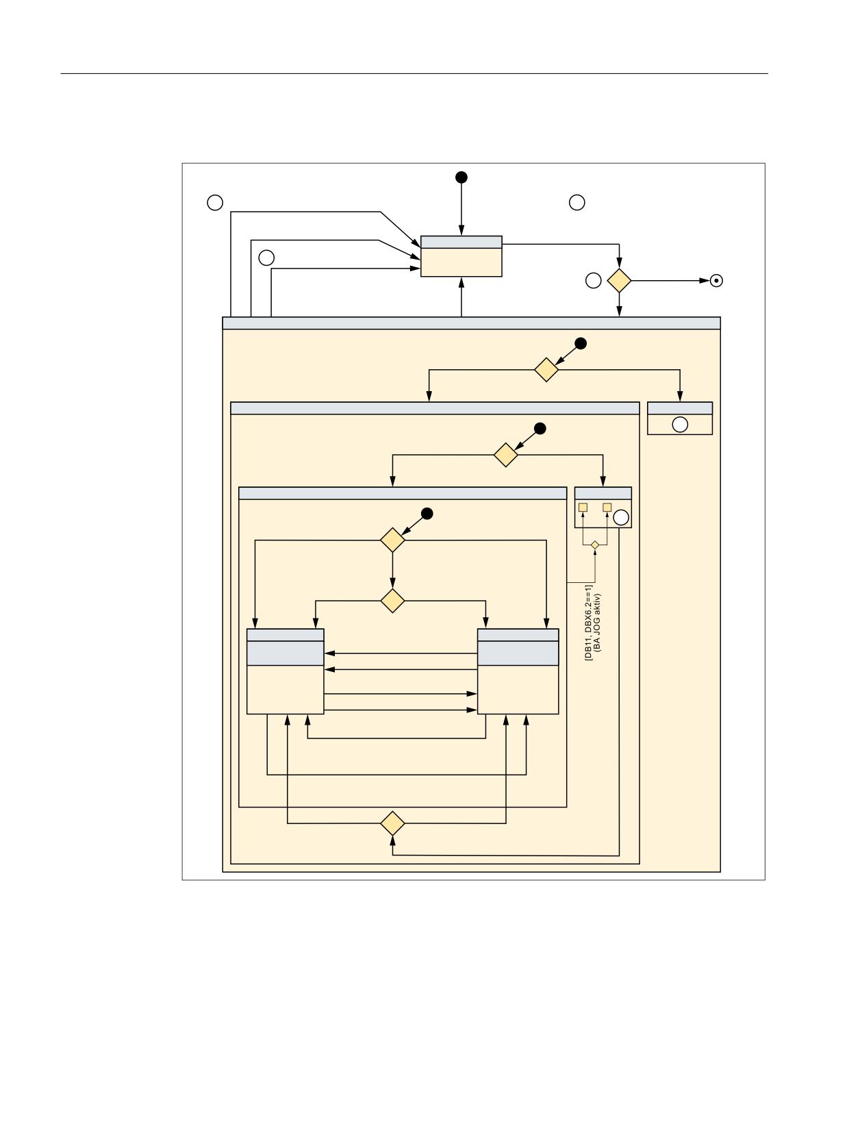
State diagram: Protection area
3527$
1&. 5HVHW
8SGDWH$OO&D6\V9DU([FHSW,QLW6WDW 6%
8SGDWH$OO&D6\V9DU 6%
3527$ 5
8SGDWH$OO&D6\V9DU 6%
&KHFN,QW1FN&D6\V9DU,PDJHV 6%
6% QLFKW LQLWLDOLVLHUW
35276 5
8SGDWH&D6\V9DU,QLW6WDW 6%
>)$/6(@
'(/2%- 3527B$5($
>758(@ 8SGDWH1&.0RGHOO 6%
6FKXW]EHUHLFK LQLWLDOLVLHUW
>LQW3URW7\SH>6%@
0$&+,1( @
>LQW3URW7\SH>6%@
722/ @
0DVFKLQHQVFKXW]EHUHLFK
:HUN]HXJ 6%
>'%
'%;
25
@
>'%
'%;
@
%$ $8720$7,. 25 0'$ DNWLY
%$ -2* DNWLY
%$ $8720$7,.
0'$
%$ -2*
>LQW,QLW6WDW>6%@
$ @
>LQW,QLW6WDW>6%@
, @
LQS,QLW6WDW>6%@
3
>LQW%LW1R>6%@
$1'
>LQW%LW1R>6%@
$1'
'%
'%;
LQS%LW
@
'%
'%;
LQS%LW
@
'%
'%;
LQS%LW
'%
'%;
LQS%LW
6% ¾EHUZDFKW
6% QLFKW ¾EHUZDFKW
(QWU\
35276
$
(QWU\
LQW6WDW>6%@
$
LQW6WDW>6%@
$
>'%
'%;
@
35276 ,
>'%
'%;
@
LQW,QLW6WDW>6%@
3
$1'
LQW%LW1R>6%@
$1'
'%
'%;
LQS%LW
'%
'%;
LQS%LW
LQW,QLW6WDW>6%@
3
$1'
LQW%LW1R>6%@
$1'
'%
'%;
LQS%LW
'%
'%;
LQS%LW
'%
'%;
'%
'%;
'%
'%;
25
%$ $8720$7,. 25 0'$ DNWLY
SB
Protection area
BA
Operating mode
①
UpdateAllCaSysVar(SB) function
All system variables of the collision avoidance are read into NC-internal variables:
int... = $N...
Special functions
278
Function Manual, 12/2018, A5E40874099B AB
K9: collision avoidance, internal
7.1 Function description
② UpdateAllCaSysVarExeptInitStat(SB) function
As with the UpdateAllCaSysVar(SB) function, but the $NP_INIT_STAT system variable is not
read in. Internally in the NC, the last value of the intInitStat initialization status is therefore re-
tained.
③ CheckIntNckCaSysVarImages(SB) function
The NC-internal variables read in from the system variables are checked for consistency.
Return value when an error is detected: FALSE; if error-free: TRUE.
④ UpdateCaSysVarInitStat(SB) function
Only the system variable $NP_INIT_STAT is read into the NC-internal variable intInitStat.
⑤ The internal structure of the "Tool protection area" state is the same as the "Machine protection
area" state.
⑥ The internal structure of the "JOG mode" state is the same as the "AUTO/MDA mode" state.
7.1.5
Tools
Modeling
Protection areas for tools can be modeled automatically from the collision avoidance and be
updated automatically following a tool change with some limitations. The following conditions
must be fulfilled for this purpose:
● The protection area for the tool is modeled as an automatic tool protection area (type:
TOOL). See system variable $NP_PROT_TYPE (Page 238)
● The tool is managed by the control tool management.
● The tool data stored in the tool management matches the actual geometric dimensions of
the tool.
● The collision avoidance recognizes the completion of the tool change. Normally, by
programming the corresponding tool offset number Dx, with x = 0, 1, 2, 3, ...
● The collision avoidance recognizes the automatic tool protection area for which the tool
was changed.
● If the tool path refers to a normalized tool, the tool radius of the actual tool is specified as
either positive or negative deviations referred to the normalized tool. In this case, collision
avoidance calculates with the following values:
- Positive value: Tool radius = specified value, however, as a minimum, the value of the
parameterized collision tolerance
- Negative value: Tool radius = value of the parameterized collision tolerance
Special functions
Function Manual, 12/2018, A5E40874099B AB
279
K9: collision avoidance, internal
7.1 Function description
Change to the machine model
If a tool which is located in a magazine or tool adapter modeled in the active machine model
of the collision avoidance is changed in the machine then the machine model must be updated.
This is the case where one of the following actions is carried out, for example:
● A tool is loaded / unloaded in a tool magazine modeled in the machine model.
Example: Tool change in a revolver (circular) magazine.
Update: The machine model update must be explicitly requested by the user using
PROTA once the tool change has completed.
● The tool that is in a tool holder is changed.
Example: Tool change in the tool holder of the main spindle.
Update: The machine model is automatically updated following the tool change (standard:
M6) with output of the programmed tool offset number Dx in the main run.
Tool changes
The collision avoidance only updates the active machine model after a tool change without an
explicit request by PROTA if a tool offset is selected (output of the programmed tool offset
number Dx at the NC/PLC interface).
However, at the control, tool changes can be made, which are not associated with a tool offset
selection. However, for these changes the active machine model is not updated. These types
of tool changes include, for example:
● Loading/unloading a tool at the user interface.
SINUMERIK Operate: Operating area "Parameter" > "Tool list" > Vertical softkey: "Loading"
or "Unloading"
● Carrying out a tool change via the PLC user program
● Directly writing to the tool buffer memory using the system variable $TC_MPP6[9998,
<location>]
● SETMS(<spindle number>): Changing the master spindle in the channel
● TMMVTL: PI service "Prepare magazine location for loading, unload tool"
Reference Function Manual Basic Functions; Chapter: "P3: Basic PLC program for
SINUMERIK 840D sl" > "Component descriptions" > "PI services" > "PI service: TMMVTL"
● MVTOOL: Command to move a tool
Reference Function Manual Tool Management; Chapter "Programming > "NC language
commands" > "MVTOOL - language command to move a tool"
If such a change is carried out, then the machine manufacturer must be requested to update
the machine module via the PLC user program. Examples of options include:
● A new channel reset is requested if the channel is in the "reset" state. When the reset
response is appropriately set (MD20110 $MC_RESET_MODE_MASK), then the actual tool
offset number Dxis output again.
● Starting an ASUB or manufacturer's cycle, which includes the output of the tool offset
number Dx and the request to update the machine model (PROTA).
Tool wear
Minimal tool changes do not have to be taken into account in the machine model, as generally
they are far less than the collision clearance.
Special functions
280
Function Manual, 12/2018, A5E40874099B AB
K9: collision avoidance, internal
7.1 Function description
If a tool change occurs, which is relevant for collision avoidance, e.g. diameter changes for
grinding tools, then these must be taken into account by explicitly requesting that the machine
model is updated (PROTA).
No change to the machine model
The active machine model does not change if a fully modeled machine part with tools, e.g. a
tool magazine, is moved in the machine.
Example: Revolver magazine on a lathe
The revolver magazine on a lathe is fully modeled in the machine model of the collision
avoidance:
● The geometry of the magazine and the tools located inside it
● The motions of the magazine through the machine axes
A rotation of the revolver magazine then does not represent a change to the machine model:
● since no tools are changed inside the machine model the geometries of all the protection
areas remain unchanged.
● As the motions of the protection areas by the machine axes are fully captured by the collision
avoidance via the kinematic chain.
Supplementary conditions
Several spindles in the channel
For configurations with several spindles in the channel, the collision avoidance function
assumes that a tool change takes place in the master spindle of the channel (S1). As a result
only the automatic tool protection area of the master spindle is updated through the collision
avoidance once the tool change has taken place.
Unsupported tool configurations
Tool configurations in accordance with ISO modes 4 and 5 (H numbers) along with "flat D
numbers" are not supported by the collision avoidance.
7.1.6
Boundary conditions
Channel assignment
All of the machine components relevant for collision avoidance must be located in the first
channel of the NC:
● All axes and spindles of the kinematic chain.
See Chapter "K7: Kinematic chain (Page 191)"
● All tools of the automatic tool protection areas of the geometric machine modeling.
See Chapter "K8: Geometric machine modeling (Page 225)"
Special functions
Function Manual, 12/2018, A5E40874099B AB
281

K9: collision avoidance, internal
7.1 Function description
Allowance for the following error
The collision avoidance uses the position setpoints of the relevant machine axes for the
clearance calculation of the protection areas. However, the actual positions of the machine
axes differ from the position setpoint by the following error. For this reason, there is also a
difference between the position setpoint and the actual position for the protection areas. This
difference must be taken into account by the user through configuration of a suitably large
safety clearance or enlargement of the protection area.
Compensations
The various compensation functions of the NC - for instance, temperature, spindle and pitch
error and sag compensation - ensure that positions programmed in the workpiece coordinate
system are actually assumed in the machine coordinate system. The collision avoidance takes
into account the position corrections made by the compensation functions.
WARNING
Risk of collision
If compensations are used for other purposes, e.g. in order to implement axis couplings in
the machine coordinate system, the collision avoidance working with position setpoints can
no longer be performed reliably. There is a risk of collision.
Actual value offset in the machine coordinate system with PRESETON
With active collision avoidance and use of an actual value offset in the machine coordinate
system with PRESETON, it is the sole responsibility of the user to ensure that the geometric
model of the collision avoidance remains consistent.
WARNING
Risk of collision
If an actual value offset is made in the machine coordinate system with PRESETON and the
geometric model of the collision avoidance not adapted accordingly, the collision avoidance
working with position setpoints can no longer be performed reliably. There is a risk of collision.
Block search
For the following types of block search there are no collision calculations carried out:
● Type 1: Block search without calculation
● Type 2: Block search with calculation at the contour
● Type 4: Block search with calculation at block end point
With the following type of block search collision calculations are carried out (in the
preprocessing) for:
● Type 5: Block search with calculation in "Program test" (SERUPRO) mode
Special functions
282
Function Manual, 12/2018, A5E40874099B AB
K9: collision avoidance, internal
7.2 Commissioning
AUTOMATIC modes: Incomplete protection area data for collision
When a large number of protection areas have been configured, in exceptional cases, the
following behavior can occur:
● Several protection areas have approached one another, down to the collision tolerance
● Only two protection areas are specified in Alarm 26260 "Collision two protection areas" that
is displayed.
● The collision of the other protection areas is only displayed when manually traversing the
axes after changing into the JOG mode.
7.2
Commissioning
7.2.1
General
7.2.1.1
Overview
The commissioning of the "Collision avoidance" function is performed using:
● Machine data
- Specification of the quantity structure
- Specification of general properties of the collision pairs
● System variables
- Parameterization of the collision pairs and their properties
7.2.1.2
Structure of the system variables
The system variables are structured according to the following scheme:
$NP_<name>[<index_1>,<index_2>]
Note
Index_2 is not available for all system variables.
General
The system variables to describe the protection areas have the following properties:
● Prefix: $NP_, (N for NC, P for protection).
● They can be read and written via NC programs.
● They can be stored in archives and loaded to the NC again.
Special functions
Function Manual, 12/2018, A5E40874099B AB
283
K9: collision avoidance, internal
7.2 Commissioning
Data type
STRING
All system variables of the STRING data type have the following properties:
● Maximum string length: 31 characters
● No distinction is made between upper and lower case
Example: "Axis1" is identical to "AXIS1"
● Spaces and special characters are permitted
Example: "Axis1" is not identical to "Axis 1"
● Names that start with two underscores "__" are reserved for system purposes and must
not be used for user-defined names.
Note
Leading space
Since spaces are valid and distinct characters, names that start with a space followed by two
underscores "__" can, in principle, be used for user-defined names. However, because they
can be easily mistaken for system names, this procedure is not recommended.
Index_1
The individual protection areas are addressed via index_1. Index 0 → 1st protection area, index
1 → 2nd protection area, ... n → (n+1) protection area, where n =
($MN_MM_MAXNUM_3D_PROT_AREAS - 1)
All system variables of a protection area have the same index.
Index_2
For system variables that define a collision pair, the protection areas of the collision pair are
addressed via index_2.
●
0 → 1. Protection area
●
1 → 2. Protection area
See also
Deletion of components (DELOBJ) (Page 215)
Special functions
284
Function Manual, 12/2018, A5E40874099B AB
K9: collision avoidance, internal
7.2 Commissioning
7.2.2
Machine data
7.2.2.1
Collision tolerance
The collision tolerance (accuracy of the collision check) for all protection areas of the NC
monitored for collision is set with the machine data. If the clearance of two safety areas is less
than the collision clearance, i.e. the sum of safety clearance (Page 285) and collision tolerance,
then there is a collision.
MD10619 $MN_COLLISION_TOLERANCE = <collision tolerance>
Accuracy of automatic generated protection areas
The collision tolerance also determines the accuracy of the protection area bodies of protection
areas produced automatically, e.g. automatic tool protection areas. The accuracy of the
protection area bodies approached using triangle areas is 1/3 of the collision tolerance.
Effects
The smaller the collision tolerance is set, the greater the number of triangular areas required
for the modelling of the automatically generated protection areas and the computation time
required for the collision detection.
Recommended setting
Collision tolerance ≈ 1 mm
See also
Reaction of the control to a risk of collision (Page 275)
7.2.2.2
Safety clearance
The safety clearance for all protection areas of the NC monitored for collision is set with the
machine data. The collision avoidance ensures that the safety clearance is not violated.
MD10622 $MN_COLLISION_SAFETY_DIST = <safety clearance>
Note
Collision pair-specific safety clearance
If a specific safety clearance has been set for a collision pair via the system variable
$NP_SAFETY_DIST (Page 289), this has priority over the NC-specific safety clearance set in
the machine data.
See also
Reaction of the control to a risk of collision (Page 275)
Special functions
Function Manual, 12/2018, A5E40874099B AB
285

K9: collision avoidance, internal
7.2 Commissioning
7.2.2.3
Maximum memory space
The maximum value of the memory space in KB that can be allocated to the collision avoidance
is set with the machine data.
MD18896 $MN_MM_MAXNUM_3D_COLLISION = <value>
Value
Meaning
0
The maximum value of the memory space is determined automatically by the control using
the following machine data:
● MD18890 $MN_MM_MAXNUM_3D_PROT_AREAS
● MD18892 $MN_MM_MAXNUM_3D_PROT_AREA_ELEM
● MD18894 $MN_MM_MAXNUM_3D_FACETS_INTERN
● MD18895 $MN_MM_MAXNUM_3D_FACETS
> 0
Maximum value = parameterized value [KB]
Note
Only one > 0 value must be entered in the machine data when one of the following alarms is
displayed:
● Alarm 26262 "Insufficient memory space for the collision check of two protection areas"
● Alarm 26263 "Insufficient memory space for determining the clearance of two protection
areas"
Used memory space
Various system variables are available to determine the memory space used by the collision
avoidance. See section "Memory requirement (Page 291)".
7.2.2.4
Maximum number of collision pairs
The maximum number of possible collision pairs has an impact on:
● Length m of the system variable fields (e.g. $NP_COLL_PAIR[ m, ... ] )
● The user memory required for collision avoidance
● The size of the commissioning archive
The maximum number of collision pairs can be restricted with machine data:
MD18898 $MN_MM_MAXNUM_3D_COLL_PAIRS = <value>
<Val-
Meaning
ue>
0
The following applies to the maximum number of possible collision pairs MCP:
MCP = maximum value of the machine data
x > 0
The following applies to the maximum number of possible collision pairs MCP:
MCP = x, with 0 < x ≤ maximum value of the machine data
A value greater than the maximum permissible value of the machine data is limited internally to the
maximum value. No feedback regarding this is sent to the user.
Special functions
286
Function Manual, 12/2018, A5E40874099B AB

K9: collision avoidance, internal
7.2 Commissioning
7.2.2.5
Protection levels for collision avoidance On/Off
The protection level for switching the collision avoidance On/Off is set with the machine data
via the user interface. The protection level can be specified according to operating mode and
protection area type.
Machine data = <protection level>
Number
Identifier: $MN_
Meaning: Protection level for switching the colli-
sion avoidance On/Off
MD51160
ACCESS_WRITE_CA_MACH_JOG
Machine protection areas, JOG/MDI operating
mode
MD51161
ACCESS_WRITE_CA_MACH_AUTO
Machine protection areas, AUTOMATIC mode,
MD51162
ACCESS_WRITE_CA_TOOL
Tool protection areas
References
A detailed description of protection levels can be found in:
Function Manual, Basic Functions, Section: "A2: Various NC/PLC interface signals and
functions" > "Functions" > "Access protection via password and keyswitch"
7.2.3
System variables
7.2.3.1
Overview
A collision pair is parameterized with the following system variables:
Name
Meaning
$NP_COLL_PAIR
Name of a collision pair protection area
$NP_SAFETY_DIST
Safety clearance of the protection area pair
The system variables are described in detail in the following sections.
Note
Establish a defined initial state
It is recommended that a defined initial state be generated before parameterizing the collision
avoidance. To do this, set the system variables of the collision avoidance to their default values
with the DELOBJ() (Page 215) function.
Change system variable values
If the value of one of the system variables listed above is changed, the change becomes
immediately visible at the user interface, e.g. SINUMERIK Operate. The machine model of the
NC is only updated after explicitly requesting that the machine model is recalculated by calling
the PROTA() (Page 294) or PROTS() (Page 295) function.
Special functions
Function Manual, 12/2018, A5E40874099B AB
287

K9: collision avoidance, internal
7.2 Commissioning
7.2.3.2
$NP_COLL_PAIR
Function
The names of the two protection areas, which form a collision pair, is entered in a system
variable. The two protection areas can be in any sequence.
Collision pairs
As the collision check requires a lot of computation time, it does not make sense to monitor
all parameterized protection areas for collision with one another through the collision
avoidance. Examples in which a collision check does not make sense:
● Protection areas that cannot collide because of the construction
● Protection areas that have been defined without anchoring to the kinematic chain
The user must define which parameterized protection areas can actually collide on the machine
and define them as collision pairs. Only these protection areas are monitored by the collision
avoidance.
To define a collision pair, the names of the two protection areas must be entered in two system
variables with the same collision pair index. One protection area under the protection area
index 0, the other under the protection area index 1.
Part of a collision pair
Using the COLLPAIR() (Page 293) function, a check can be made as to whether two protection
areas are parameterized as collision pair.
Syntax
$NP_COLL_PAIR[<m>,<i>] = "<name>"
Meaning
$NP_COLL_PAIR:
Name of the first or second protection area of a collision pair
Data type:
STRING
Default value:
"" (empty string)
<m>:
System variable or collision pair index
Data type:
INT
Range of values:
0, 1, 2, ... (M -1) 1)
<i>:
Protection area index
Data type:
INT
Range of values:
0 (first protection area), 1 (second protection area)
<name>:
Protection area name
Data type:
STRING
1)
M = n * (n - 1) / 2
where n = $MN_MM_MAXNUM_3D_PROT_AREAS
Special functions
288
Function Manual, 12/2018, A5E40874099B AB

K9: collision avoidance, internal
7.2 Commissioning
Example
Two protection areas defined with the names "Rotary table" and "Tool in spindle" are to be
checked for collision. The two protection areas are to be mutually monitored for collision. The
definition for this is in the seventh collision pair:
Program code
Comment
N100 $NP_COLL_PAIR[6,0] = "Rotary ta-
; 7th collision pair,
ble"
; 1st Protection area
N110 $NP_COLL_PAIR[6,1] = "Tool in spin-
; 7th collision pair,
dle"
; 2nd Protection area
Supplementary conditions
● When forming a collision pair, it should be observed that every protection area of this pair
has at least one protection area element that is marked with $NP_USAGE (Page 253) =
"C" or "A". Otherwise, with the protection area, it is not permissible to perform a collision
or clearance calculation (Page 296).
● The protection areas of a collision pair are only checked for collision when both protection
areas are in the "Protection area monitored" state. See Chapter "State diagram: Protection
area (Page 278)".
7.2.3.3
$NP_SAFETY_DIST
Function
The collision pair-specific safety clearance is entered in the system variable. The collision
avoidance ensures that this safety clearance is not violated.
If a value not equal to 0.0 is entered in the system variable, the general safety clearance from
MD10622 $MN_COLLISION_SAFETY_DIST (Page 285) is not taken into account for this
collision pair.
If the value 0.0 is entered in the system variable, the safety clearance set in the machine data
applies.
Syntax
$NP_SAFETY_DIST[<m>] = <value>
Meaning
$NP_SAFETY_DIST:
Safety clearance of the collision pair
Data type:
REAL
Default value:
0.0
Special functions
Function Manual, 12/2018, A5E40874099B AB
289

K9: collision avoidance, internal
7.2 Commissioning
<m>:
System variable or protection area index
Data type:
INT
Range of values:
0, 1, 2, ... (M -1) 1)
<value>:
Safety clearance
Data type:
REAL
Range of values:
0.0 ≤ x ≤ +max. REAL value
Unit:
mm or inch depending on the current dimensions set-
ting
1)
M = n * (n - 1) / 2
where n = $MN_MM_MAXNUM_3D_PROT_AREAS
Example
The safety clearance for the protection areas of the seventh collision pair should be 1.0 mm
(input system: metric).
Program code
Comment
N100 $NP_SAFETY_DIST[6] = 1.0
; 7. collision pair,
; safety clearance = 1.0
See also
Reaction of the control to a risk of collision (Page 275)
7.2.4
Extend system variables
7.2.4.1
Overview
Further information on the internal states and values of the collision avoidance can be read
via the following system variables:
● State data (Page 291)
● Memory requirement (Page 291)
● Braking distance estimations (Page 292)
Special functions
290
Function Manual, 12/2018, A5E40874099B AB

K9: collision avoidance, internal
7.2 Commissioning
7.2.4.2
State data
The state data of the collision avoidance can be read via the following system variables (OPI
variables)
System variable
OPI variable
Meaning
$AN_COLL_STATE[<m>]
anCollState[<m>]
Current state of a protection area (active/inactive) with
regard to the collision avoidance
$AN_COLL_STATE_COND[<m>]
anCollStateCond[<m>]
Monitoring state (bit-coded) of a protection area
$AN_COLL_IPO_ACTIVE
anCollIpoActive
Activation state of the collision avoidance in the main
run (active/inactive)
$AN_COLL_IPO_LIMIT
anCollIpoLimit
Velocity reduction through collision avoidance in the
main run (active/inactive)
$AN_COLL_LOAD[<i>] 1)
anCollLoad[<i>] 1)
Computation time requirement for the collision avoid-
ance function <i>
$AN_ACTIVATE_COLL_CHECK[<j>]
anActivateColl-
Current state of the NC/PLC interface with index <j>
Check[<j>]
for each 8 bytes:
DB10, DBX234.0 - DBX.241.7 (activate protection
areas)
$AN_COLL_CHECK_OFF
anCollCheckOff
Current state of the NC/PLC interface:
DB10 DBX58.0 - 7 (disable protection area group)
$AA_COLLPOS[<a>]
aaCollPos
Position of axis <a> in the machine coordinate system
(MCS) when the last collision alarm occurred
$AC_COLLPOS[<k>]
acCollPos
Vector <k> for the collision position in the world coor-
dinate system when the last collision alarm occurred
a: Axis name
i: 0 = function 1, 1 = function 2, 2 = function 3, ...
j: Index 0, 1, 2, ... for one bit field each of 8 bytes.
k: Coordinate index k = 1, 2, 3 for X, Y, Z coordinates
m: System variable or protection area index 0, 1, 2, ... (MD18890 $MN_MM_MAXNUM_3D_PROT_AREAS - 1)
1) The system variable can be reset by writing the value 0. Every other value is rejected with an error message.
References
● For a detailed description of the system variables, refer to:
List Manual, System Variables
● A detailed description of the interface signals can be found in:
List Manual, Interface signals
7.2.4.3
Memory requirement
The data for the memory requirement of the collision avoidance can be read via the following
system variables (OPI variables).
System variable
OPI variable
Meaning
$AN_COLL_MEM_AVAILABLE
anCollMemAvailable
Size of the memory space in KB reserved for the collision
avoidance.
$AN_COLL_MEM_USE_MIN 1)
anCollMemUseMin 1)
Minimum value of the memory space used for the collision
avoidance as a percentage of the reserved memory.
Special functions
Function Manual, 12/2018, A5E40874099B AB
291

K9: collision avoidance, internal
7.2 Commissioning
System variable
OPI variable
Meaning
$AN_COLL_MEM_USE_MAX 1)
anCollMemUseMax 1)
Maximum value of the memory space used for the collision
avoidance as a percentage of the reserved memory.
$AN_COLL_MEM_USE_ACT 1)
anCollMemUseAct 1)
Actual value of the memory space used for the collision avoid-
ance as a percentage of the reserved memory.
1) The system variable can be reset by writing the value 0. Every other value is rejected with an error message.
References
For a detailed description of the system variables, refer to:
List Manual, System Variables
7.2.4.4
Braking distance estimations
The estimated total braking distance (linear approximation) and the proportional braking
distances of superimposed motions for an axis can be read via the following system variables
(OPI variables). The estimation only takes the current state of the axis into account. It returns,
e.g. the braking distance 0.0 for an axis that is just at the reversal point as part of a circular
path.
Note
The system variables are used for support in the development of user-specific functions as
part of the collision avoidance, and similar functions.
Table 7-1
Basic coordinate system (BCS)
System variable
OPI variable
Meaning
Total braking distance
$AA_DTBREB[<a>]
aaDtbreb
Estimated, linearly approximated total braking dis-
tance
Proportional braking distances for superimposed motions
$AA_DTBREB_CMD[<a>]
aaDtbrebCmd
Command component
$AA_DTBREB_CORR[<a>]
aaDtbrebCorr
Correction component
$AA_DTBREB_DEP[<a>]
aaDtbrebDep
Coupling component
<a>: Axis name
Table 7-2
Machine coordinate system (MCS)
System variable
OPI variable
Meaning
Total braking distance
$AA_DTBREM[<a>]
aaDtbrem
Estimated, linearly approximated total braking dis-
tance
Proportional braking distances for superimposed motions
$AA_DTBREM_CMD[<a>]
aaDtbremCmd
Command component
$AA_DTBREM_CORR[<a>]
aaDtbremCorr
Correction component
Special functions
292
Function Manual, 12/2018, A5E40874099B AB
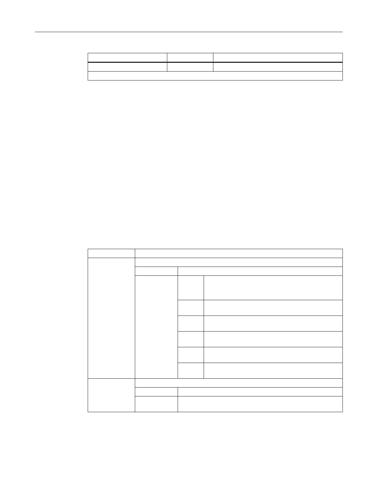
K9: collision avoidance, internal
7.3 Programming
System variable
OPI variable
Meaning
$AA_DTBREM_DEP[<a>]
aaDtbremDep
Coupling component
<a>: Axis name
References
For a detailed description of the system variables, refer to:
List Manual, System Variables
7.3
Programming
7.3.1
Check for collision pair (COLLPAIR)
The COLLPAIR() function determines whether two protection areas form a collision pair.
Syntax
[<RetVal> =] COLLPAIR(<Name_1>,<Name_2>[,<NoAlarm>)])
Meaning
COLLPAIR:
Check whether part of a collision pair
<RetVal>:
Function return value
Data type:
INT
Value:
≥ 0
The two protection zones form a collision pair.
Return value == collision pair index m (see
$NP_COLL_PAIR (Page 288))
-1
Either two strings have not been specified or at least
one of the two is the zero string.
-2
The protection zone specified in the first parameter has
not been found.
-3
The protection zone specified in the second parameter
has not been found.
-4
Neither of the two specified protection zones has been
found.
-5
Both specified protection zones have been found, but
not together in a collision pair.
<Name_1>:
Name of the first protection zone
Data type:
STRING
Range of val-
Parameterized protection zone names
ues:
Special functions
Function Manual, 12/2018, A5E40874099B AB
293
K9: collision avoidance, internal
7.3 Programming
<Name_2>:
Name of the second protection area
Data type:
STRING
Range of val-
Parameterized protection zone names
ues:
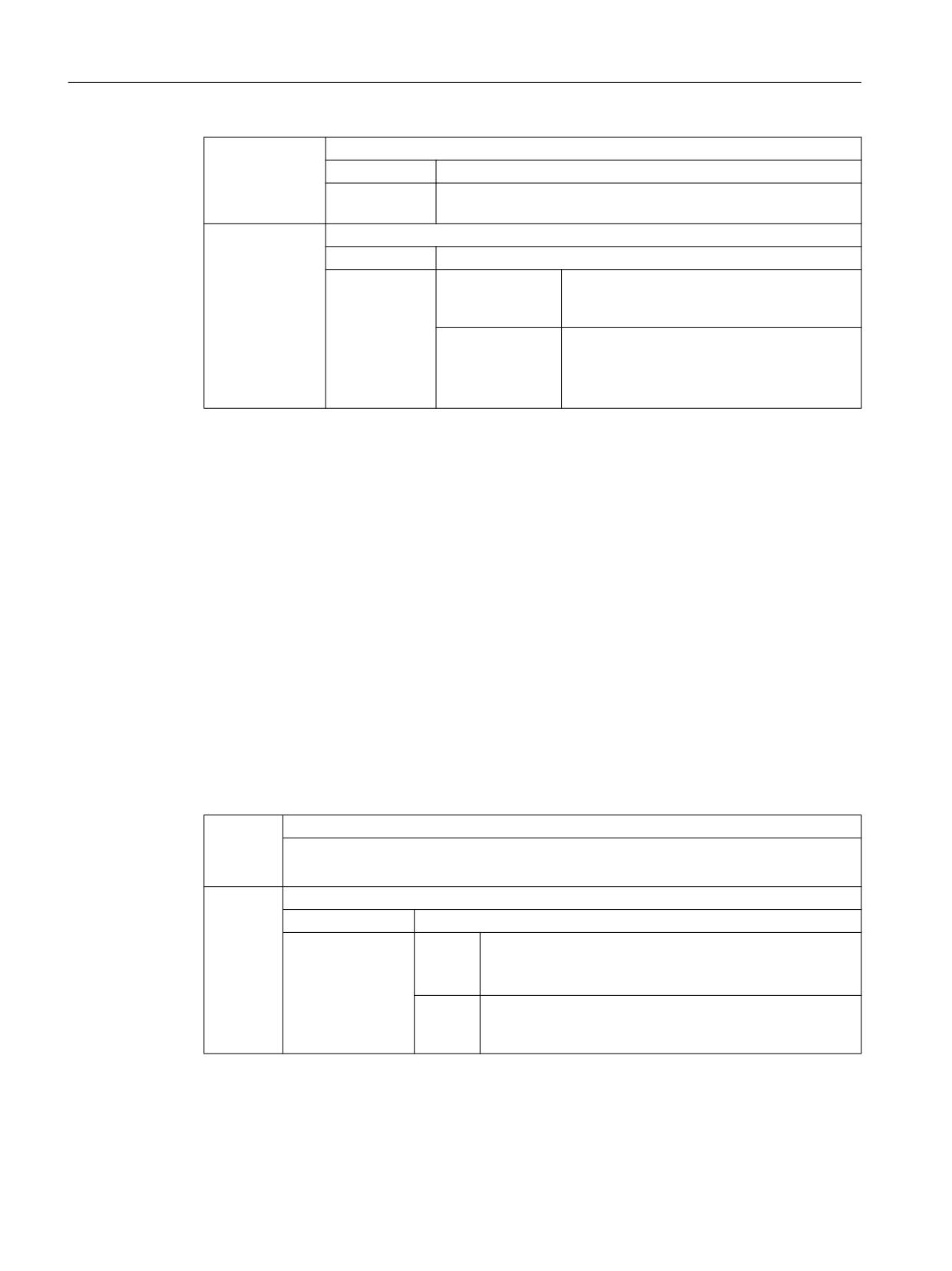
<NoAlarm>:
Alarm suppression (optional)
Data type:
BOOL
Value:
FALSE (Default)
In the event of an error (<RetVal> < 0), the
program processing is stopped and an alarm
displayed.
TRUE
In the event of an error, the program process-
ing is not stopped and no alarm displayed.
Application: User-specific reaction corre-
sponding to the return value
See also
State diagram: Protection area (Page 278)
7.3.2
Request recalculation of the machine model of the collision avoidance (PROTA)
If system variables of the kinematic chain $NK_..., the geometric machine modeling or the
collision avoidance $NP_... are written in the part program, the PROTA procedure must
subsequently be called so that the change becomes effective in the NC-internal machine model
of the collision avoidance.
Syntax
PROTA[(<Par>)]
Meaning
PROTA:
Request recalculation of the machine model of the collision avoidance
● Triggers a preprocessing stop.
● Must be alone in the block.
<Par>:
Parameter (optional)
Data type:
STRING
Value:
---
No parameters.
The machine model is recalculated. The states of the pro-
tection areas are retained.
"R"
The machine model is recalculated. The protection areas
are set to their initialization status corresponding to
$NP_INIT_STAT (Page 244).
Special functions
294
Function Manual, 12/2018, A5E40874099B AB
K9: collision avoidance, internal
7.3 Programming
Supplementary conditions
Simulation
The PROTA procedure must not be used in part programs in conjunction with the simulation
(simNC).
Example: Avoiding the PROTA call while the simulation is active.
Program code
Comment
IF $P_SIM == FALSE
; IF simulation not active
PROTA
THEN recalculate collision model
ENDIF
; ENDIF
See also
Setting the protection zone status (PROTS) (Page 295)
7.3.3
Setting the protection zone status (PROTS)
The PROTS() procedure sets the state of protection areas to the specified value.
Syntax
PROTS(<State>[,<Name_1>,...,<Name_n>])
Meaning
PROTS:
Sets the state of protection areas
● Must be alone in the block.
<State>:
Status to which the specified protection zones are to be set
Data type:
CHAR
Value:
"A"or "a"
Status: Active
"I"or "i"
Status: Inactive
"P"or "p"
Status: Preactivated or PLC-controlled 1)
"R"or "r"
Status: NC-internal value of the initialization
status 2)
Special functions
Function Manual, 12/2018, A5E40874099B AB
295

K9: collision avoidance, internal
7.3 Programming
<Name_1> ...
Name of one or more protection areas that are to be set to the specified status
<Name_n>:
(optional)
If no name is specified, the specified status is set for all defined protection zones.
Data type:
STRING
Range of values:
Parameterized protection zone names
Note
The maximum number of protection areas that can be specified as parameters
depends only on the maximum possible number of characters per program line.
1) The activation/deactivation is performed via: DB10.DBX234.0 - DBX241.7
2) The status is set to the NC-internal value of the initialization status, i.e. to the value that the system
variable $NP_INIT_STAT (Page 244) had at the time of the last PROTA( ) (Page 294) call.
7.3.4
Determining the clearance of two protection zones (PROTD)
The PROTD() function calculates the clearance of two protection areas.
Function properties:
● The clearance calculation is performed independent of the protection area status (activated,
deactivated, preactivated).
● To calculate the clearance of two protection areas, only protection area elements are used,
which are marked with $NP_USAGE (Page 253) = "C" or "A". Protection area elements of
the protection area, which are marked with $NP_USAGE = "V", are not taken into
consideration.
● Protection areas, where all protection area elements of the protection area are marked with
$NP_USAGE = "V", cannot be used for the clearance calculation.
● The clearance calculation is performed with the positions valid at the end of the previous
block.
● Overlays that are included in the main run calculation (e.g. DRF offset or external zero
offset) are included in the clearance calculation with the values valid at the function
interpretation time.
Note
Synchronization
When using the PROTD() function, it is the sole responsibility of the user to synchronize
the main run and preprocessing, if required, with the STOPRE preprocessing stop.
Collision
If there is a collision between the specified protection areas, the function returns a clearance
of 0.0. There is a collision if both the protection areas touch or intersect each other.
The safety clearance for the collision check (MD10622 $MN_COLLISION_SAFETY_DIST) is
not taken into account in the clearance calculation.
Syntax
[<RetVal> =] PROTD([<Name_1>],[<Name_2>],VAR <Vector>[,<System>])
Special functions
296
Function Manual, 12/2018, A5E40874099B AB

K9: collision avoidance, internal
7.3 Programming
Meaning
PROTD:
Calculates the clearance of the two specified protection areas.
● Must be alone in the block.
<RetVal>:
Function return value: Absolute clearance value of the two protection areas or 0.0
with collision (see above: Collision paragraph)
Data type:
REAL
Range of values:
0.0 ≤ x ≤ +max. REAL value
<Name_1>,
Names of the two protection areas whose clearance is to be calculated (optional)
<Name_2>:
Data type:
STRING
Range of values:
Parameterized protection area names
Default value:
"" (empty string)
If no protection areas have been specified, the function calcu-
lates the current smallest clearance from all the activated and
preactivated protection areas in the collision model.
<Vector>:
Return value: 3-dimensional clearance vector from protection area <Name_2> to
protection area <Name_1> with:
● <Vector>[0]: X coordinate in the world coordinate system
● <Vector>[1]: Y coordinate in the world coordinate system
● <Vector>[2]: Z coordinate in the world coordinate system
For collision: <Vector> == zero vector
Data type:
VAR REAL [3]
Range of values:
<Vector> [n]: 0.0 ≤ x ≤ ±max. REAL value
<System>:
Measuring system (inch/metric) for clearance and clearance vector (optional)
Data type:
BOOL
Value:
FALSE (Default)
Measuring system corresponding to the cur-
rently active G command from G group 13
(G70, G71, G700, G710).
TRUE
Measuring system corresponding to the set
basic system:
MD52806 $MN_ISO_SCALING_SYSTEM
Special functions
Function Manual, 12/2018, A5E40874099B AB
297

K9: collision avoidance, internal
7.4 Example
7.4
Example
7.4.1
Specifications
General Information
The basic procedure when parameterizing collision avoidance using a part program is shown
using a simplified 3-axis milling machine as example. All of the system variables relevant for
collision avoidance are written to the part program:
● Kinematic chain $NK_...
● Geometric machine modeling $NP_...
● Collision avoidance $NP_...
The machine model is subsequently activated in the part program, so that after executing the
part program, the collision avoidance has been completely parameterized in the 3-axis milling
machine and is active.
Option and machine data
The following option and machine data must be set for the example:
No.
Option data: $ON_
Value
MD19830
COLLISION_MASK
1
No.
Machine data: $MN_
Value
MD10619
COLLISION_TOLERANCE
1
MD18880
MM_MAXNUM_KIN_CHAIN_ELEM
10
MD18890
MM_MAXNUM_3D_PROT_AREAS
10
MD18892
MM_MAXNUM_3D_PROT_AREA_ELEM
10
MD18893
MM_MAXNUM_3D_T_PROT_ELEM
1
MD18894
MM_MAXNUM_3D_FACETS_INTERN
1000
MD18895
MM_MAXNUM_3D_FACETS
3000
MD18896
MM_MAXNUM_3D_COLLISION
0
MD18897
MM_MAXNUM_3D_INTERFACE_IN
16
MD18899
PROT_AREA_TOOL_MASK
1
Special functions
298
Function Manual, 12/2018, A5E40874099B AB
K9: collision avoidance, internal
7.4 Example
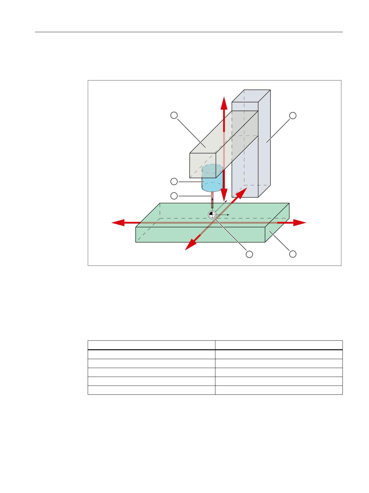
Principle design of the 3-axis milling machine
The principle machine design is shown in the following diagram.
=
<
=
;
;
<
① Z axis
② Stand
③ Table
④ Machine zero = reference point
⑤ Tool
⑥ Tool holder
The machine parts and/or protection areas are assigned to the following machine axes.
Machine parts and/or protection areas
Machine axis
Table
X1, Y1
Z axis
Z1
Column
---
Tool holder
Z1
Tool
Z1
Special functions
Function Manual, 12/2018, A5E40874099B AB
299
K9: collision avoidance, internal
7.4 Example
Dimension drawing
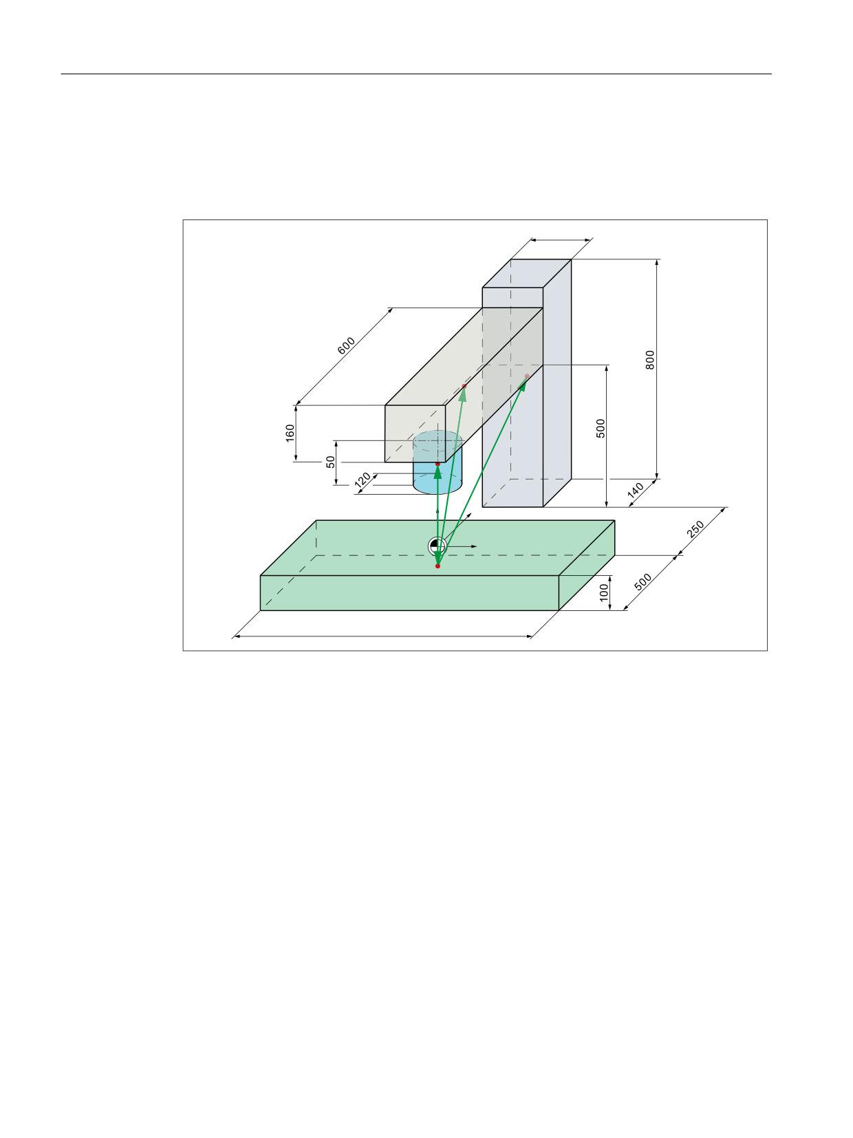
The dimensions of the protection area elements as well as their position (vectors to the center
point of the protection area element) referred to the machine zero point are specified in the
following dimension drawing.
9=$
96
=
<
97
;
97
Vectors to the center point of the protection area elements
vtool
Tool adapter (0;0;25)
vZA
Z axis (0;200;130)
vS
Column (0;570;350)
vT
Table (0;0;-50)
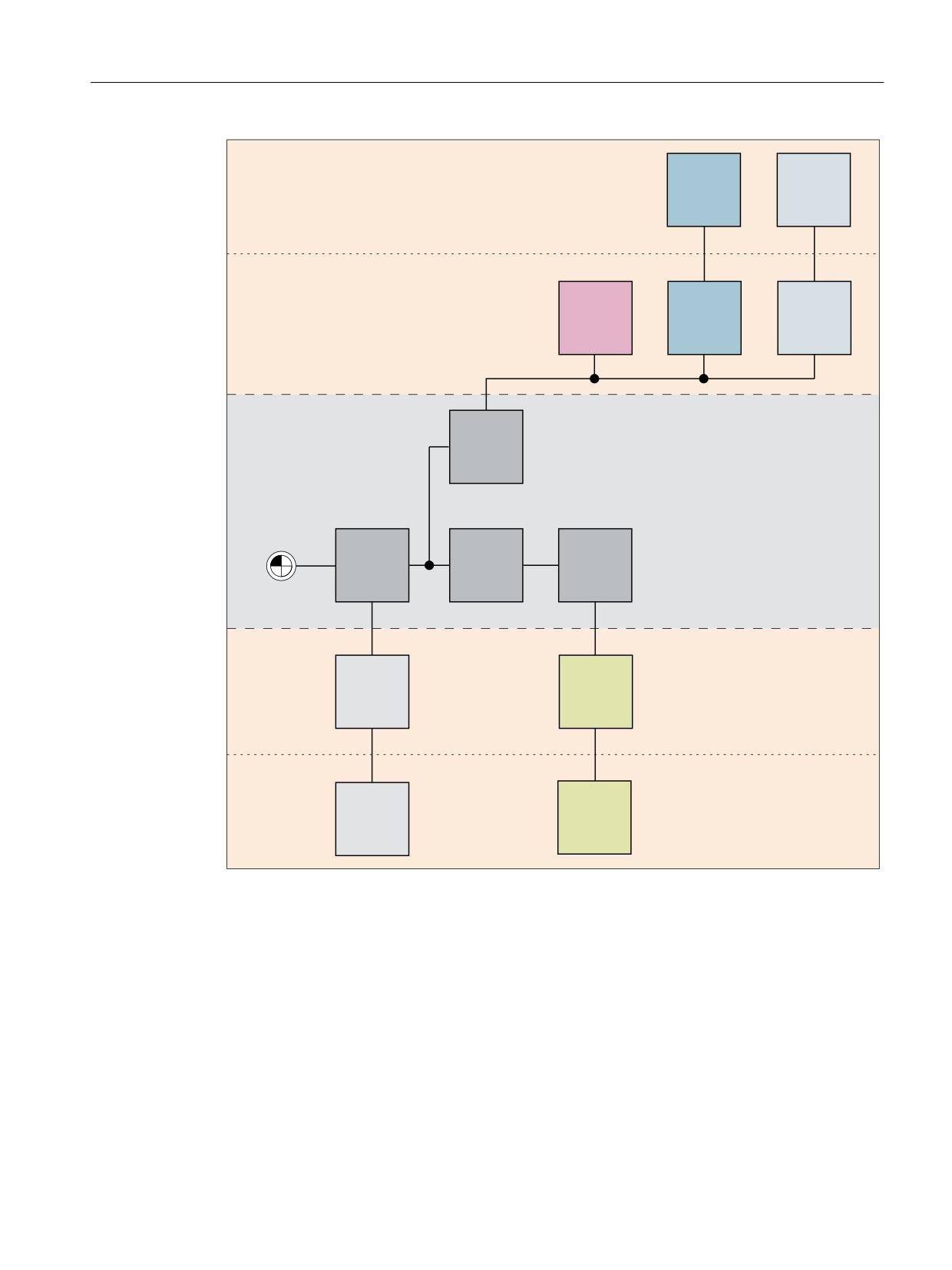
Kinematic chain
The kinematic chain (see next diagram) starts with an "Offset" type element. These are
assigned to all static protection areas of the machine. In the example, this is only the "Column"
protection area.
The kinematic elements of the machine axes follow the offset element:
● Z axis and X axis traverse independently of one another ⇒ $NK_PARALLEL
● The Y axis traverses dependent on the X axis ⇒ $NK_NEXT
The various protection areas of the geometric machine modeling are assigned the kinematic
elements of the machine axes
Special functions
300
Function Manual, 12/2018, A5E40874099B AB
K9: collision avoidance, internal
7.4 Example
*HRPHWULF PDFKLQH PRGHOLQJ
3URWHFWLRQ DUHD HOHPHQWV
&</,1'(5
%2;
7
7
= D[LV
722/
$FFHSWDQFH
3URWHFWLRQ DUHDV
0$&+,1(
0$&+,1(
.LQHPDWLF FKDLQ
= D[LV
$;,6B/,1
2))6(7
; D[LV
< D[LV
$;,6B/,1
$;,6B/,1
7DEOH
6WDQG
3URWHFWLRQ DUHDV
0$&+,1(
0$&+,1(
%2;
%2;
3URWHFWLRQ DUHD HOHPHQWV
Collision pairs
For the example, it is assumed that only the following collision pairs are to be taken into account:
● Tool adapter - table
● Tool - table
Special functions
Function Manual, 12/2018, A5E40874099B AB
301
K9: collision avoidance, internal
7.4 Example
7.4.2
Part program of the machine model
Program code
;***********************************************************
;************************* Example ************************
; milling machine: 3 linear axes, 1 spindle
;
table
=> X1, Y1
;
Z axis, tool adapter, tool => Z1
;***********************************************************
; status: February 11, 2013, 15:34
;
;===========================================================
; Collision machine data used
;===========================================================
; MD10619 $MN_COLLISION_TOLERANCE = 1
;
; MD18880 $MN_MM_MAXNUM_KIN_CHAIN_ELEM
=
100
; MD18890 $MN_MM_MAXNUM_3D_PROT_AREAS
=
10
; MD18892 $MN_MM_MAXNUM_3D_PROT_AREA_ELEM =
10
; MD18893 $MN_MM_MAXNUM_3D_T_PROT_ELEM
=
100
; MD18894 $MN_MM_MAXNUM_3D_FACETS_INTERN
= 1000
; MD18895 $MN_MM_MAXNUM_3D_FACETS
= 3000
; MD18896 $MN_MM_MAXNUM_3D_COLLISION
=
0
; MD18897 $MN_MM_MAXNUM_3D_INTERFACE_IN
=
16
; MD18899 $MN_PROT_AREA_TOOL_MASK
=
1
;
; MD19830 $ON_COLLISION_MASK = 1
; option
;
;
;===========================================================
; Definitions
;===========================================================
DEF INT RETVAL = 0
; return value of the delete function
;
DEF INT C_NKE = 0
; index for kinematic elements
DEF INT C_NPC = 0
; index for protection areas
DEF INT C_NPE = 0
; index for protection area elements
DEF INT C_NPP = 0
; index for collision pairs
;
;
Special functions
302
Function Manual, 12/2018, A5E40874099B AB
K9: collision avoidance, internal
7.4 Example
Program code
;===========================================================
; initialization of the collision data
;===========================================================
MSG("protection areas")
G4 F3
; reset all parameters to their initial setting
;
RETVAL = DELOBJ("KIN_CHAIN_ELEM")
IF (RETVAL <> 0)
MSG("error: DELOBJ KIN_CHAIN_ELEM")
G4 F5
ENDIF
;
RETVAL = DELOBJ("PROT_AREA_ALL")
IF RETVAL <> 0
MSG("error: DELOBJ PROT_AREA_ALL")
G4 F5
ENDIF
;
RETVAL = DELOBJ("PROT_AREA_COLL_PAIRS")
IF RETVAL <> 0
MSG("error: DELOBJ PROT_AREA_COLL_PAIRS")
G4 F5
ENDIF
;
;
;===========================================================
; kinematic chain
;===========================================================
; KE1: ROOT
; ----------------------------------------------------------
$NK_NAME[C_NKE]
= "ROOT"
$NK_NEXT[C_NKE]
= "X axis"
$NK_PARALLEL[C_NKE]
= ""
$NK_TYPE[C_NKE]
= "OFFSET"
;
$NK_OFF_DIR[C_NKE, 0] = 0.0
; X
$NK_OFF_DIR[C_NKE, 1] = 0.0
; Y
$NK_OFF_DIR[C_NKE, 2] = 0.0
; Z
;
$NK_AXIS[C_NKE]
= ""
$NK_A_OFF[C_NKE]
= 0.0
;
C_NKE = C_NKE + 1
; next kinematic element
;
Special functions
Function Manual, 12/2018, A5E40874099B AB
303
K9: collision avoidance, internal
7.4 Example
Program code
; ----------------------------------------------------------
; kinematic element: X axis
; ----------------------------------------------------------
$NK_NAME[C_NKE]
= "X axis"
$NK_NEXT[C_NKE]
= "Y axis"
$NK_PARALLEL[C_NKE]
= "Z axis"
$NK_TYPE[C_NKE]
= "AXIS_LIN"
;
$NK_OFF_DIR[C_NKE, 0] = 1.0
; X
$NK_OFF_DIR[C_NKE, 1] = 0.0
; Y
$NK_OFF_DIR[C_NKE, 2] = 0.0
; Z
;
$NK_AXIS[C_NKE]
= "X1"
$NK_A_OFF[C_NKE]
= 0.0
;
C_NKE = C_NKE + 1
; next kinematic element
;
; ----------------------------------------------------------
; kinematic element: Y axis
; ----------------------------------------------------------
$NK_NAME[C_NKE]
= "Y axis"
$NK_NEXT[C_NKE]
= ""
$NK_PARALLEL[C_NKE]
= ""
$NK_TYPE[C_NKE]
= "AXIS_LIN"
;
$NK_OFF_DIR[C_NKE, 0] = 0.0
; X
$NK_OFF_DIR[C_NKE, 1] = 1.0
; Y
$NK_OFF_DIR[C_NKE, 2] = 0.0
; Z
;
$NK_AXIS[C_NKE]
= "Y1"
$NK_A_OFF[C_NKE]
= 0.0
;
C_NKE = C_NKE + 1
; next kinematic element
;
; ----------------------------------------------------------
; kinematic element: Z axis
; ----------------------------------------------------------
$NK_NAME[C_NKE]
= "Z axis"
$NK_NEXT[C_NKE]
= ""
$NK_PARALLEL[C_NKE]
= ""
$NK_TYPE[C_NKE]
= "AXIS_LIN"
;
$NK_OFF_DIR[C_NKE, 0] = 0.0
; X
$NK_OFF_DIR[C_NKE, 1] = 0.0
; Y
$NK_OFF_DIR[C_NKE, 2] = 1.0
; Z
;
$NK_AXIS[C_NKE]
= "Z1"
$NK_A_OFF[C_NKE]
= 0.0
;
C_NKE = C_NKE + 1
; next kinematic element
;
;
Special functions
304
Function Manual, 12/2018, A5E40874099B AB
K9: collision avoidance, internal
7.4 Example
Program code
;===========================================================
; protection areas with protection area elements
;===========================================================
; protection area 1: Column
; ----------------------------------------------------------
$NP_PROT_NAME[C_NPC]
= "Column"
$NP_PROT_TYPE[C_NPC]
= "MACHINE"
$NP_CHAIN_ELEM[C_NPC] = "ROOT"
$NP_1ST_PROT[C_NPC]
= "SBE column"
$NP_PROT_COLOR[C_NPC] = 'HFFA0A0A4'
; AARRGGBB
$NP_BIT_NO[C_NPC]
= -1
$NP_INIT_STAT[C_NPC]
= "A"
;
C_NPC = C_NPC + 1
; next protection area
;
; ----------------------------------------------------------
; protection area element 1.1: SBE column
; ----------------------------------------------------------
$NP_NAME[C_NPE]
= "SBE column"
$NP_NEXT[C_NPE]
= ""
$NP_NEXTP[C_NPE]
= ""
$NP_TYPE[C_NPE]
= "BOX"
;
cube dimensions
$NP_PARA[C_NPE,0]
= 160.0
; length
$NP_PARA[C_NPE,1]
= 140.0
; width
$NP_PARA[C_NPE,2]
= 800.0
; height
;
center point
$NP_OFF[C_NPE,0]
=
0.0
; X
$NP_OFF[C_NPE,1]
= 570.0
; Y: xxx rear table edge
$NP_OFF[C_NPE,2]
= 350.0
; Z: Lower edge equal to lower edge table
;
$NP_DIR[C_NPE,0]
=
0.0
$NP_DIR[C_NPE,1]
=
0.0
$NP_DIR[C_NPE,2]
=
0.0
;
$NP_ANG[C_NPE]
=
0.0
;
$NP_COLOR[C_NPE]
=
0
$NP_D_LEVEL[C_NPE]
=
0
$NP_USAGE[C_NPE]
= "V"
; V = visualize only
$NP_FILENAME[C_NPE] = ""
;
C_NPE = C_NPE + 1
; next protection area element
;
Special functions
Function Manual, 12/2018, A5E40874099B AB
305
K9: collision avoidance, internal
7.4 Example
Program code
;++++++++++++++++++++++++++++++++++++++++++++++++++++++++++
; protection area 2: Tool adapter
; ----------------------------------------------------------
$NP_PROT_NAME[C_NPC]
= "Tool adapter"
$NP_PROT_TYPE[C_NPC]
= "MACHINE"
$NP_CHAIN_ELEM[C_NPC] = "Z axis"
$NP_1ST_PROT[C_NPC]
= "SBE tool adapter"
$NP_PROT_COLOR[C_NPC] = 'HFF0000FF'
; AARRGGBB
$NP_BIT_NO[C_NPC]
= -1
$NP_INIT_STAT[C_NPC]
= "A"
;
C_NPC = C_NPC + 1
; next protection area
;
; ----------------------------------------------------------
; protection area element 2.1: SBE tool adapter
; ----------------------------------------------------------
$NP_NAME[C_NPE]
= "SBE tool adapter"
$NP_NEXT[C_NPE]
= ""
$NP_NEXTP[C_NPE]
= ""
$NP_TYPE[C_NPE]
= "CYLINDER"
;
cylinder dimensions
$NP_PARA[C_NPE,0]
= 50.0
; height
$NP_PARA[C_NPE,1]
= 60.0
; radius
$NP_PARA[C_NPE,2]
=
0.0
;
center point
$NP_OFF[C_NPE,0]
=
0.0
; X
$NP_OFF[C_NPE,1]
=
0.0
; Y
$NP_OFF[C_NPE,2]
= 25.0
; Z: Half height
;
$NP_DIR[C_NPE,0]
=
0.0
$NP_DIR[C_NPE,1]
=
0.0
$NP_DIR[C_NPE,2]
=
0.0
;
$NP_ANG[C_NPE]
= 0.0
;
$NP_COLOR[C_NPE]
= 0
$NP_D_LEVEL[C_NPE]
= 0
$NP_USAGE[C_NPE]
= "A"
$NP_FILENAME[C_NPE] = ""
;
C_NPE = C_NPE + 1
; next protection area element
;
Special functions
306
Function Manual, 12/2018, A5E40874099B AB
K9: collision avoidance, internal
7.4 Example
Program code
; ++++++++++++++++++++++++++++++++++++++++++++++++++++++++++
; protection area 3: Tool
; ----------------------------------------------------------
$NP_PROT_NAME[C_NPC]
= "Tool"
$NP_PROT_TYPE[C_NPC]
= "TOOL"
$NP_CHAIN_ELEM[C_NPC] = "Z axis"
$NP_1ST_PROT[C_NPC]
= ""
$NP_PROT_COLOR[C_NPC] = 'HFFFF0000'
; AARRGGBB
$NP_BIT_NO[C_NPC]
= -1
$NP_INIT_STAT[C_NPC]
= "A"
;
only relevant for type "TOOL"
$NP_INDEX[C_NPC,0]
= 1
; tool location No. / spindle No.
$NP_INDEX[C_NPC,1]
= 9998
; magazine No. / -
$NP_INDEX[C_NPC,2]
= 1
; TOA area
;
C_NPC = C_NPC + 1
; next protection area
;
Special functions
Function Manual, 12/2018, A5E40874099B AB
307
K9: collision avoidance, internal
7.4 Example
Program code
; ++++++++++++++++++++++++++++++++++++++++++++++++++++++++++
; protection area 4: Z axis
; ----------------------------------------------------------
$NP_PROT_NAME[C_NPC]
= "Z axis"
$NP_PROT_TYPE[C_NPC]
= "MACHINE"
$NP_CHAIN_ELEM[C_NPC] = "Z axis"
$NP_1ST_PROT[C_NPC]
= "SBE Z axis"
$NP_PROT_COLOR[C_NPC] = 'HFFA0A0A4'
; AARRGGBB
$NP_BIT_NO[C_NPC]
= -1
$NP_INIT_STAT[C_NPC]
= "A"
;
C_NPC = C_NPC + 1
; next protection area
;
; ----------------------------------------------------------
; protection area element 4.1: SBE horizontal column
; ----------------------------------------------------------
$NP_NAME[C_NPE]
= "SBE Z axis"
$NP_NEXT[C_NPE]
= ""
$NP_NEXTP[C_NPE]
= ""
$NP_TYPE[C_NPE]
= "BOX"
;
$NP_PARA[C_NPE,0]
= 160.0
$NP_PARA[C_NPE,1]
= 600.0
$NP_PARA[C_NPE,2]
= 160.0
;
$NP_OFF[C_NPE,0]
=
0.0
$NP_OFF[C_NPE,1]
= 200.0
$NP_OFF[C_NPE,2]
= 130.0
;
$NP_DIR[C_NPE,0]
= 0.0
$NP_DIR[C_NPE,1]
= 0.0
$NP_DIR[C_NPE,2]
= 0.0
;
$NP_ANG[C_NPE]
= 0.0
;
$NP_COLOR[C_NPE]
= 0
$NP_D_LEVEL[C_NPE]
= 0
$NP_USAGE[C_NPE]
= "A"
$NP_FILENAME[C_NPE] = ""
;
C_NPE = C_NPE + 1
; next protection area element
;
Special functions
308
Function Manual, 12/2018, A5E40874099B AB
K9: collision avoidance, internal
7.4 Example
Program code
; ++++++++++++++++++++++++++++++++++++++++++++++++++++++++++
; protection area 5: Table
; --------------------------------------------------------
$NP_PROT_NAME[C_NPC]
= "Table"
$NP_PROT_TYPE[C_NPC]
= "MACHINE"
$NP_CHAIN_ELEM[C_NPC] = "Y axis"
$NP_1ST_PROT[C_NPC]
= "SBE table"
$NP_PROT_COLOR[C_NPC] = 'HFF00FF00'
; AARRGGBB
$NP_BIT_NO[C_NPC]
= -1
$NP_INIT_STAT[C_NPC]
= "A"
;
C_NPC = C_NPC + 1
; next protection area
;
; ----------------------------------------------------------
; protection area element 5.1: SBE table
; ----------------------------------------------------------
$NP_NAME[C_NPE]
= "SBE table"
$NP_NEXT[C_NPE]
= ""
$NP_NEXTP[C_NPE]
= ""
$NP_TYPE[C_NPE]
= "BOX"
;
$NP_PARA[C_NPE,0]
= 1000.0
$NP_PARA[C_NPE,1]
= 500.0
$NP_PARA[C_NPE,2]
= 100.0
;
$NP_OFF[C_NPE,0]
=
0.0
$NP_OFF[C_NPE,1]
=
0.0
$NP_OFF[C_NPE,2]
= -50.0
;
$NP_DIR[C_NPE,0]
= 0.0
$NP_DIR[C_NPE,1]
= 0.0
$NP_DIR[C_NPE,2]
= 0.0
;
$NP_ANG[C_NPE]
= 0.0
;
$NP_COLOR[C_NPE]
= 0
$NP_D_LEVEL[C_NPE]
= 0
$NP_USAGE[C_NPE]
= "A"
$NP_FILENAME[C_NPE] = ""
;
C_NPE = C_NPE + 1
; next protection area element
;
;
Special functions
Function Manual, 12/2018, A5E40874099B AB
309

K9: collision avoidance, internal
7.5 Data lists
Program code
;===========================================================
; collision pairs
;===========================================================
$NP_COLL_PAIR[C_NPP, 0] = "Tool adapter"
$NP_COLL_PAIR[C_NPP, 1] = "Table"
;
C_NPP = C_NPP + 1
; next collision pair
;
$NP_COLL_PAIR[C_NPP, 0] = "Tool"
$NP_COLL_PAIR[C_NPP, 1] = "Table"
;
C_NPP = C_NPP + 1
; next collision pair
;
;
;===========================================================
; activating the machine model
;===========================================================
PROTA
PROTS("A")
;
M2
;========================= ENDE ===========================
7.5
Data lists
7.5.1
Machine data
7.5.1.1
NC-specific machine data
Number
Identifier: $MN_
Description
MD10619
COLLISION_TOLERANCE
Collision tolerance
MD10622
COLLISION_SAFETY_DIST
Safety clearance
MD18896
MM_MAXNUM_3D_COLLISION
Memory location for the collision avoidance
7.5.2
System variables
Identifier
Description
$NP_COLL_PAIR
Name of the first or second protection area of a collision pair
$NP_SAFETY_DIST
Safety clearance of the collision pair
$AN_COLL_STATE
Current state of a protection area with regard to the collision avoidance
$AN_COLL_STATE_COND
Monitoring state (bit-coded) of a protection area
Special functions
310
Function Manual, 12/2018, A5E40874099B AB

K9: collision avoidance, internal
7.5 Data lists
Identifier
Description
$AN_COLL_IPO_ACTIVE
Activation state of the collision avoidance in the main run
$AN_COLL_IPO_LIMIT
Velocity reduction through collision avoidance in the main run
$AN_COLL_LOAD
Computation time requirement for the collision avoidance function
$AN_ACTIVATE_COLL_CHECK
Current state of the NC/PLC interface DB10, DBX234.0 - DBX.241.7 (activate
protection areas)
$AN_COLL_CHECK_OFF
Current state of the NC/PLC interface DB10, DBB58 (switch off protection
area groups depending on the operating mode)
$AA_COLLPOS
Position of an axis in the MCS when the last collision alarm occurred
$AC_COLLPOS
Vector for the collision position in the world coordinate system when the last
collision alarm occurred
$AN_COLL_MEM_AVAILABLE
Size of the memory space in KB reserved for the collision avoidance.
$AN_COLL_MEM_USE_MIN
Minimum value of the memory space used for the collision avoidance as a
percentage of the reserved memory.
$AN_COLL_MEM_USE_MAX
Maximum value of the memory space used for the collision avoidance as a
percentage of the reserved memory.
$AN_COLL_MEM_USE_ACT
Actual value of the memory space used for the collision avoidance as a per-
centage of the reserved memory.
$AA_DTBREB
Estimated, linearly approximated total braking distance (BCS)
$AA_DTBREB_CMD
Command component (BCS)
$AA_DTBREB_CORR
Correction component (BCS)
$AA_DTBREB_DEP
Coupling component (BCS)
$AA_DTBREM
Estimated, linearly approximated total braking distance (MCS)
$AA_DTBREM_CMD
Command component (MCS)
$AA_DTBREM_CORR
Correction component (MCS)
$AA_DTBREM_DEP
Coupling component (MCS)
7.5.3
Signals
7.5.3.1
Signals to NC
Signal name
SINUMERIK 840D sl
SINUMERIK 828D
Collision avoidance: Deactivate protection area group (PLC DB10.DBX58.0 - 7
DB2600.DBX2.0 - 7
→ NC)
Collision avoidance: Activate protection area (PLC → NC)
DB10.DBX234.0 - DBX241.7
DB2600.DBX4.0 - DBX11.7
7.5.3.2
Signals from NC
Signal name
SINUMERIK 840D sl
SINUMERIK 828D
Collision avoidance: Protection area active
DB10.DBX226.0 - DBX233.7
DB2700.DBX20.0 - DBX27.7
Special functions
Function Manual, 12/2018, A5E40874099B AB
311

K9: collision avoidance, internal
7.5 Data lists
7.5.3.3
Signals from channel
Signal name
SINUMERIK 840D sl
SINUMERIK 828D
Collision avoidance: Stop
DB21,
DBX377.0
DB33xx.DBX4005.0
7.5.3.4
Signals from axis
Signal name
SINUMERIK 840D sl
SINUMERIK 828D
Collision avoidance: Velocity reduction
DB31,
DBX77.0
DB39xx.DBX1003.0
Special functions
312
Function Manual, 12/2018, A5E40874099B AB
K11 Collision avoidance, external
8
8.1
Description of the function
8.1.1
Options
The function "Collision avoidance, external" is an option that requires a license:
● Collision avoidance ADVANCED (machine, workpiece): 6FC5800-0AS04-0YB0
8.1.2
Characteristics
The function "Collision avoidance, external" provides a proprietary data interface at the
Industrial Ethernet interface X120 of the NCU module. The following data are transferred in
real time via this interface:
● Setpoint and actual values of the machine axes for monitoring and visualizing machine
movements
● Status data and input data for influencing traversing movements
● Signals for monitoring the external application
Based on these data, an independent application for machine visualization and collision
avoidance can be implemented by a SINUMERIK product partner on an external computer.
8.2
Commissioning
8.2.1
Machine data
8.2.1.1
Functions of external collision avoidance
The functions of external collision avoidance are enabled with machine data:
MD16900 $MN_COLLISION_EXT_FUNKTION_MASK.Bit x = 1
Bit
Meaning
0
Activate UDP interface
1 - 31
reserved
Special functions
Function Manual, 12/2018, A5E40874099B AB
313
K11 Collision avoidance, external
8.2 Commissioning
8.2.1.2
Preview time
The preview time is set with machine data:
MD16901 $MN_COLLISION_EXT_PREVIEW_TIME = <preview time>
8.2.1.3
Preview time step
The size of a time step for calculating the movement preview is set in machine data:
MD16902 $MN_COLLISION_EXT_PREVIEW_STEP = <preview time>
8.2.1.4
Timeout time
The time within which the external application must have reported back to the control for sign-
of-life monitoring is set in machine data:
MD16903 $MN_COLLISION_EXT_TIMEOUT = <timeout time>
If the external application does not report back within the set time, alarm 26300 "Sign of life
failure of the external collision avoidance" is displayed.
Special functions
314
Function Manual, 12/2018, A5E40874099B AB
K12 transformation definitions with kinematic chains
9
9.1
Function description
9.1.1
Characteristics
In this chapter, a description is provided as to how transformations are mapped using a
kinematic chain and parameterized in the control system using system variables. The system
variables are retentatively saved in the NC and can be archived and/or read as "NC data" via
SINUMERIK Operate using the commissioning archive.
Transformations via kinematic chains
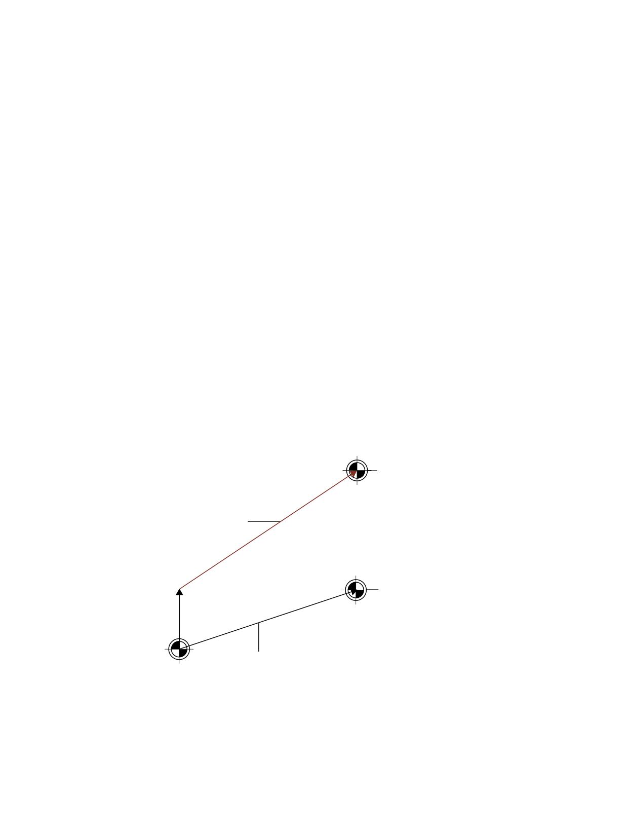
The machine kinematics relevant to kinematic transformations is described by two kinematic
chains:
● One chain points from the machine zero point (zero point of the world coordinate system)
to the workpiece reference point (part segment).
● The other chain points from the machine zero point to the tool reference point (tool
segment).
One of the two chains can also be empty (for pure table or tool kinematics).
=HUR SRLQW RI WKH WRRO
FRRUGLQDWH V\VWHP
7RRO FKDLQ
=HUR SRLQW RI WKH
ZRUNSLHFH FRRUGLQDWH
V\VWHP
:RUNSLHFH FKDLQ
=HUR SRLQW RI WKH ZRUOG
FRRUGLQDWH V\VWHP
Figure 9-1
Definition of a transformation via kinematic chains
Both kinematic chains are merged internally into a single kinematic chain, which, by definition,
begins at the workpiece reference point and ends at the tool reference point.
Special functions
Function Manual, 12/2018, A5E40874099B AB
315

K12 transformation definitions with kinematic chains
9.1 Function description
Definition of the kinematic transformation
The definition of kinematic transformations via kinematic chains is used to standardize the
definition of the previous transformation types.
The following transformations are taken into consideration:
● TRAORI
- TRAORI_DYN; dynamic orientation transformation
- TRAORI_STAT; static orientation transformation
● TRANSMIT_K; face side transformation
● TRACYL_K; peripheral surface transformation
● TRAANG_K; oblique angle transformation
See also
System variables (Page 198)
K7: Kinematic chain (Page 191)
9.1.2
Definition of kinematic transformations
Transformations with kinematic chains are defined in two steps:
● Definition of the machine kinematics
● Definition of the transformation
Defining machine kinematics
The machine kinematics (geometry of the machine) is described via kinematic chains. For
detailed information, see K7: Kinematic chain (Page 191).
The system variables that are relevant to this are described under System variables
(Page 198). These system variables are structured according to the scheme $NK_... Important
system variables include:
System variable
$NK_NAME
Name of the current element
$NK_NEXT
Name of the next element
$NK_PARALLEL
Defines a parallel kinematic chain. As a result, the second chain can be defined parallel
to the first chain.
$NK_TYPE
Defines the type of the element, e.g. AXIS_LIN, AXIS_ROT, OFFSET, ROT_CONST,
SWITCH
$NK_OFF_DIR
Defines the rotation vector relative to the machine axis
$NK_AXIS
Name of the machine axis
$NK_A_OFF
Defines the work offset of the assigned machine axis.
Special functions
316
Function Manual, 12/2018, A5E40874099B AB

K12 transformation definitions with kinematic chains
9.1 Function description
Defining transformation
The description of the machine kinematics with kinematic chains is not sufficient to completely
specify a kinematic transformation. The transformations can be completely defined via system
variables with the $NT_... prefix. The system variables available for the transformation are
divided into the following parts:
● System variables that are relevant for all transformations.
● System variables that are only relevant for specific transformations.
You can find a complete list under System variables for general transformation types
(Page 337). Among other things, the following general system variables are available:
System variable
Description
$NT_NAME
Name of the transformation dataset.
$NT_TRAFO_INDEX
Identifier for alternative transformation activation; a transformation defined with kinematic
chains can also be activated using the conventional language commands (e.g. TRAORI)
instead of the TRAFOON method.
$NT_TRAFO_TYPE
Type of transformation (TRAORI_DYN, TRAORI_STAT, TRAANG_K, TRANSMIT_K,
TRACYL_K)
$NT_T_CHAIN_LAST_ELEM
Name of the last element of the kinematic chain to the tool.
$NT_P_CHAIN_LAST_ELEM
Name of the last element of the kinematic chain to the workpiece.
$NT_T_CHAIN_FIRST_ELEM
Name of the first element in the tool chain
$NT_P_CHAIN_FIRST_ELEM
Name of the first element of the workpiece chain
$NT_GEO_AX_NAME
Names of the elements of the geometry axes. With $NT_GEO_AX_NAME, a maximum of
3 linear axes are referenced. The linear axes carry out the compensating movements
which result from the kinematic transformation.
$NT_ROT_AX_NAME
Names of the elements of the orientation axes. With $NT_ROT_AX_NAME, a maximum
of 3 linear axes are referenced.
$NT_CLOSE_CHAIN_T
Reference element for closing the kinematic chain to the workpiece.
$NT_ROT_AX_OFFSET
Position offset of a/the rotary axis for the active transformation.
$NT_CNTRL
Control word
An orientation transformation is defined, for example, via the elements displayed in the graphic.
Special functions
Function Manual, 12/2018, A5E40874099B AB
317
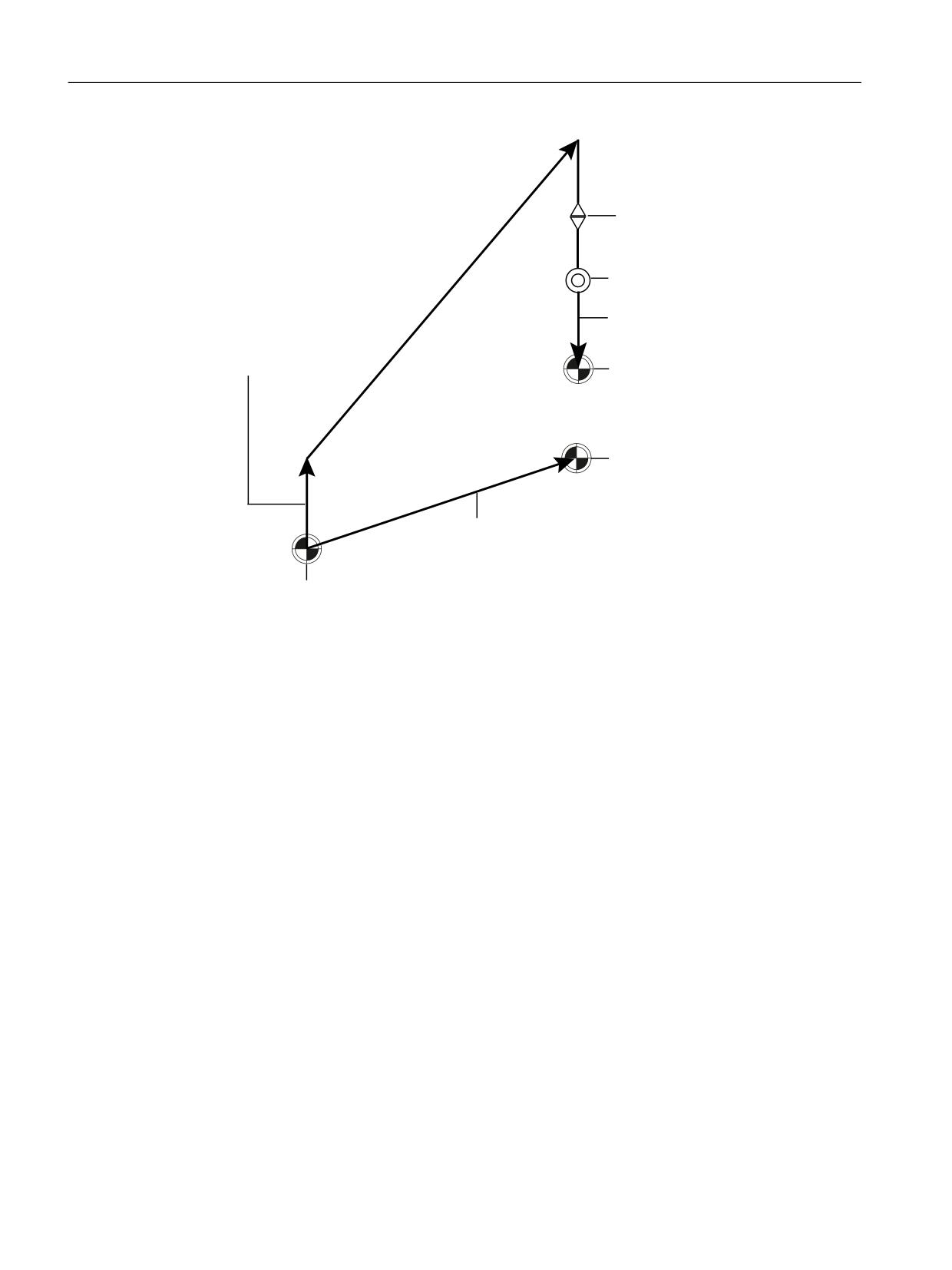
K12 transformation definitions with kinematic chains
9.1 Function description
& D[LV
17B527B$;B1$0(>P F@
% D[LV
17B527B$;B1$0(>P E@
; < = D[HV
%DVH WRRO RIIVHW
17B*(2B$;B1$0(>P [@
17B7B&+$,1B/$67B(/(0
17B*(2B$;B1$0(>P \@
17B*(2B$;B1$0(>P ]@
7RRO UHIHUHQFH SRLQW
:RUNSLHFH UHIHUHQFH
SRLQW
7DEOH RIIVHW
17B3B&+$,1B/$67B(/(0
=HUR SRLQW RI WKH ZRUOG
FRRUGLQDWH V\VWHP
Figure 9-2
Transformation elements in the kinematic chain
See also
Examples (Page 381)
9.1.3
Dynamic orientation transformation TRAORI_DYN
A dynamic orientation transformation is understood to mean a kinematic transformation in
which the movements of any rotary axes are compensated by compensation movements of a
maximum of three linear axes in such a way that the coordinates of the tool tip in the workpiece
coordinate system remain unchanged. The same applies for movements of additional
(redundant) linear axes.
The system variables that are especially used for orientation transformations are described
under Additive system variable for orientation transformation (Page 362).
The different orientation transformations are mapped via the dynamic orientation
transformation:
Special functions
318
Function Manual, 12/2018, A5E40874099B AB

K12 transformation definitions with kinematic chains
9.1 Function description
5-axis transformation
Different versions are possible for the 5-axis transformation, see 5-axis transformation
(Page 43). Generally this transformation is comprised of up to 3 linear axes and up to 2 rotary
axes.
3 and 4-axis transformation
3 and 4-axis transformations are special cases of the 5-axis transformation, see 3-axis and 4-
axis transformations (Page 57). Possible versions are listed below:
Transformation
Characteristics
3-axis transformation
2 translation axes (linear axes)
1 rotary axis
4-axis transformation
3 translation axes (linear axes)
1 rotary axis
Defining machine kinematics
The corresponding machine kinematics must be defined via a kinematic chain.
Linear axes (geometry axes)
The movements of the rotary axes are compensated via compensating movements of up to
three linear axes. The linear axes are defined via the kinematic chain as an element of the
type "AXIS_LIN". For the transformation, they are referenced with $NT_GEO_AX_NAME. The
geometry axes do not have to be vertical on top of one another and their position relative to
one another can be changed by means of rotary axes. However, the limitation that they cannot
be linearly dependent on one another applies.
The position of linear axes that are not defined as geometry axes is not changed by the
transformation.
Rotary and orientation axes
The rotary axes are defined via the kinematic chain as an element of the type "AXIS_ROT".
For the transformation, they are referenced with $NT_ROT_AX_NAME and are thus
designated as orientation axis. The position of these axes is assumed to be changeable to
achieve a specific orientation.
An offset from zero can be defined using system variable $NT_ROT_AX_OFFSET for the rotary
axes (1, 2, or 3) of the orientation transformation.
All of the other rotary axes are redundant rotary axes and are included in the calculation with
their current position values (constant rotations). Redundant machine axes (real rotary axes)
must be located in the kinematic chain in front of the first orientation axis. Additional redundant
rotary axes (manual rotary axes or rotating machine axes) can be inserted at any point.
The number of rotary axes is restricted to 6.
Special functions
Function Manual, 12/2018, A5E40874099B AB
319
K12 transformation definitions with kinematic chains
9.1 Function description
Tool orientation
The tool orientation can be specified as vector. The system variables $NT_BASE_ORIENT or
$NT_BASE_ORIENT_NORMAL are available for this. The orientations come into effect if no
tool is selected. If the vectors are not explicitly defined, the default setting is (0, 0, 1).
● $NT_BASE_ORIENT[n, 0 ...2]; defines the basic tool orientation via a vector, as shown in
the following example:
- $NT_BASE_ORIENT[1, 0] = 1.0; component in X-direction
- $NT_BASE_ORIENT[1, 1] = 1.5; component in Y-direction
- $NT_BASE_ORIENT[1, 2] = 100; component in Z-direction
● $NT_BASE_ORIENT_NORMAL[n, 0 ...2] defines a vector which stands vertically on the
basic tool orientation for orientation transformations with three degrees of freedom. If the
vectors are not explicitly defined, the default setting is (0, 1, 0).
● $NT_IGNORE_TOOL_ORIENT[n]; if the system variable is set, the values from the system
variables $NT_BASE_ORIENT and $NT_BASE_ORIENT_NORMAL are also used when a
tool is active.
Treatment of singular points (poles)
If poles (Page 54) are encountered over the course of processing, the behavior at the pole can
be set via two system variables:
● $NT_POLE_LIMIT; defines the end angle tolerance, i.e. the angle by which the polar axis
can deviate from the programmed value for the 5-axis transformation.
● $NT_POLE_TOL; defines the end angle tolerance for interpolation through the pole.
Machine measurement for orientation transformation
With the CORRTRAFO (Page 374) function, measured lever arm lengths and axis directions
can be written in correction elements:
● $NT_CORR_ELEM_T[n, 0 ...3]; names of the correction elements (type "OFFSET") in the
kinematic chain (tool chain) which can be written to by CORRTRAFO.
● $NT_CORR_ELEM_P[n, 0 ...3]; names of the correction elements (type "OFFSET") in the
kinematic chain (workpiece chain) which can be written to by CORRTRAFO.
Real-time velocity monitoring
The machine data $MC_TRAFO_ORI_ONLINE_CHECK_LIM and
$MC_TRAFO_ORI_ONLINE_CHECK_LIMR define the linear or rotary position difference
between the pre-run and main run as of which the real-time velocity monitoring and limiting is
activated. The position differences are formed from the positions of the linear and rotary axes.
Special functions
320
Function Manual, 12/2018, A5E40874099B AB
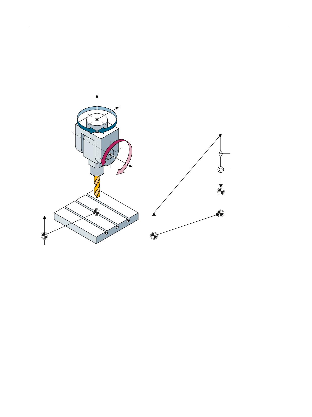
K12 transformation definitions with kinematic chains
9.1 Function description
Example of kinematics
The example schematically shows two-axis swivel head kinematics with the axis sequence
CA, as a spatial image and as a kinematic chain.
6ZLYHO KHDG
5RWDU\ D[HV & DQG $
=
&
$
&
$
; < = D[HV
ZKHUH
;
<
=
7DEOH RIIVHW
:RUNSLHFH UHIHUHQFH
=
=
SRLQW
=HUR SRLQW RI WKH ZRUOG
=HUR SRLQW RI WKH ZRUOG
:RUNSLHFH UHIHUHQFH
FRRUGLQDWH V\VWHP
FRRUGLQDWH V\VWHP
SRLQW
Figure 9-3
TRAORI example
9.1.4
Face end transformation TRANSMIT
In this chapter, a description is provided as to how a end face transformation is mapped using
a kinematic chain and parameterized in the control system using system variables. The
TRANSMIT transformation permits end face machining (drill holes, contours) on turning
machines.
The system variables are retentively saved in the NC and can be archived and/or read as "NC
data" via SINUMERIK Operate using the commissioning archive.
Special functions
Function Manual, 12/2018, A5E40874099B AB
321
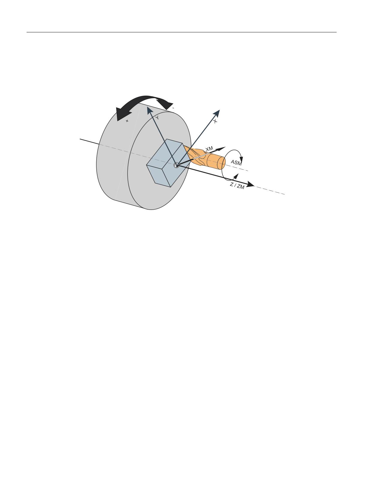
K12 transformation definitions with kinematic chains
9.1 Function description
The machine kinematics are defined using two kinematic chains, see Definition of kinematic
transformations (Page 316).
The following graphic shows an example of a end face transformation:
&0
X, Y, Z Geometry axes
CM
Machine axis; rotary axis
XM
Machine axis; linear axis, perpendicular to rotary axis
ZN
Machine axis; linear axis, parallel to rotary axis
ASM
Machine axis; work spindle
Figure 9-4
TRANSMIT
Supplementary conditions
● There must be exactly one rotary axis (the polar axis), with its name in
$NT_ROT_AX_NAME[n,1].
● One to three entries for linear axes are possible in the system parameters
$NT_GEO_AX_NAME[n,i].
Coordinate systems for end face transformations
The workpiece coordinate system and the basic coordinate system are independent of the
world coordinate system in which the kinematic chains are defined.
● The Z axis is parallel to the polar axis (axis CM - see above) and parallel to the longitudinal
axis, if it is defined.
● The geometry axes X, Y and Z are vertical to one another and form a perpendicular
coordinate system in the order 1st, 2nd and 3rd geometry axis.
● If the longitudinal axis ($NT_GEO_AX_NAME[n, 2]) exists, it must always be parallel to the
rotary axis ($NT_ROT_AX_NAME[n, 1]).
Special functions
322
Function Manual, 12/2018, A5E40874099B AB

K12 transformation definitions with kinematic chains
9.1 Function description
● If there are two linear axes, they do not have to be orthogonal to one another.
● If there are three linear axes, two axes must be orthogonal to one another. A third axis can
be at an oblique angle to one of the other two axes. There can only be one axis pair in
which the angle of the two axes is not equal to 90°. An oblique axis cannot be positioned
perpendicularly on another axis.
Kinematic chains for end face transformations
The transmit transformation is activated via the system variable $NT_TRAFO_TYPE =
"TRANSMIT_K".
Definition of the linear axes
● The X-axis is defined via the system variable $NT_GEO_AX_NAME[n,0]. This is the linear
axis of the actual TRANSMIT transformation. In the standard scenario, this axis is vertical
on the polar axis (see above).
● An entry in $NT_GEO_AX_NAME[n, 2] is optional. This axis (typically the Z-axis) is the
longitudinal axis. It must be defined parallel to the rotary axis ($NT_ROT_AX_NAME[n, 1]).
● An entry in $NT_GEO_AX_NAME[n, 1] is optional. This axis (typically the Y-axis) stands
vertically on the radial axis ($NT_GEO_AX_NAME[n, 0]) and the polar axis
($NT_ROT_AX_NAME[n, 1]) in the standard scenario.
This axis (the center offset axis) is generally used to compensate a tool offset in the Y
direction so that machining is possible up to the turning center.
Definition of a rotary axis
● The rotary axis is defined via the system variable $NT_ROT_AX_NAME[n,1]. This axis must
always be available. The direction of rotation of the rotary axis is defined via $NT_CNTRL
Bit 11.
● An offset can be defined via system variable $NT_ROT_AX_OFFSET[n, 0] for the active
TRANSMIT transformation.
Defining the order of the axes
Various settings for the transformation are defined using system variable $NT_CNTRL[n]
(Page 357). With the bits 16-18, it is binary coded how the channel axes that are entered in
$NT_ROT_AX_NAME[n, 1], in $NT_GEO_AX_NAME[n. 0] and in $NT_GEO_AX_NAME[n. 2]
are assigned to the geometry axes. The three binary numbers must correspond to the following
decimal numbers:
Decimal
Order of the geometry axes
0
X
Y
Z
1
Z
X
Y
2
Y
Z
X
3
Z
Y
X
4
X
Z
Y
5
Y
X
Z
Special functions
Function Manual, 12/2018, A5E40874099B AB
323

K12 transformation definitions with kinematic chains
9.1 Function description
Behavior when passing through the pole
The behavior when passing through the pole is defined via the system variable
$NT_POLE_SIDE_FIX
VALUE
Meaning
0
Pole crossing
The tool center point path (linear axis) must cross the pole on a continuous path.
1
Rotation around the pole.
The tool center point path must be restricted to a positive traversing range of the linear axis
(in front of turning center).
2
Rotation around the pole.
The tool center point path must be restricted to a negative traversing range of the linear
axis. (behind turning center).
Offset for the base tool
The system variable $NT_BASE_TOOL_COMP (Page 361) can be used to set whether an
offset is entered for the base tool in the transformation frame ($P_TRAFRAME) upon activation
of the transformation for each separate geometry axis. With the offset, the components of the
base tool are compensated in such as way that no change occurs in the component of the
WCS. For this function, $P_TRAFRAME must be configured via the machine data
$MC_MM_SYSTEM_FRAME_MASK bit 6.
The compensation can, for example, be used for a tool carrier, where the dimensions of the
head part of the tool carrier are not part of the tool length.
The separating point between the base tool and the tool can be defined via the system variable
$NT_T_REF_ELEM. If the system variable is blank, then the separating point is defined at the
end point of the tool chain.
Work offset of the rotary axis
In system variable $NT_ROT_OFFSET_FROM_FRAME (Page 353), you set whether the
offset for orientation axes is to be automatically applied. If a value is defined in the system
variable, then the programmed offset is automatically imported upon switch-on from the work
offset that is active for orientation axes:
Importing the rotary axis offset from the work offset upon selection of the transformation:
●
0 = Axial offset of the rotary axis is not taken into account.
●
1 = axial offset of the rotary axis is taken into account.
●
2 = Axial offset of the rotary axis is taken into account up to the SZS. SZS is the settable
zero system. The SZS frames contain transformed rotations around the rotary axis.
Special functions
324
Function Manual, 12/2018, A5E40874099B AB
K12 transformation definitions with kinematic chains
9.1 Function description
Definition of the last element in the kinematic chain
$NT_CNTRL Bit 19 is used to define that the last element of the kinematic chain is a rotary
axis or a constant rotation. The direction vector of the rotary axis defines the Z direction of the
tool coordinate system. If the system variable $NK_A_OFF of this chain element contains a
value not equal to zero, the tool coordinate system is also rotated about the coordinate axis
with this angle.
If $NT_CNTRL Bit 20 is also defined, the sign of the Z direction of the axis for the determination
of the WCS is inverted.
Example program for TRANSMIT
You will find a simple part program using TRANSMIT under Part program for TRANSMIT
(Page 388).
9.1.5
Cylinder surface transformation TRACYL
In this chapter, a description is provided as to how cylinder surface transformations (TRACYL)
are mapped using a kinematic chain and parameterized in the control system using system
variables.
The system variables are retentively saved in the NC and can be archived and/or read as "NC
data" via SINUMERIK Operate using the commissioning archive.
The machine kinematics are defined using two kinematic chains, see Definition of kinematic
transformations (Page 316).
The following graphic shows an example of a cylinder surface transformation:
&
;
%
=
Figure 9-5
Cylinder surface transformation (TRACYL)
Special functions
Function Manual, 12/2018, A5E40874099B AB
325
K12 transformation definitions with kinematic chains
9.1 Function description
Activating a transformation with TRAFOON
In addition to the name of the transformation, the reference diameter can also be specified for
TRACYL and a setting as to whether the "Slot side offset" function is active is also possible:
TRAFOON (<transformation name>, <diameter>, <k>)
With k = 1, the slot side offset is carried out, see Activating a transformation (TRAFOON)
(Page 373).
Supplementary conditions
● There must be exactly one rotary axis (the polar axis), with its name in
$NT_ROT_AX_NAME[n,1].
● There can be 1 to 3 entries for linear axes in the system parameters
$NT_GEO_AX_NAME[n,i].
Coordinate systems for cylinder surface transformations
The workpiece coordinate system and the basic coordinate system are independent of the
world coordinate system in which the kinematic chains are defined.
● The Z axis is parallel to the polar axis (axis B - see above) and parallel to the longitudinal
axis, if it is defined.
● The geometry axes X, Y and Z are vertical to one another and form a perpendicular
coordinate system in the order 1st, 2nd and 3rd geometry axis.
● If the longitudinal axis ($NT_GEO_AX_NAME[n, 2]) exists, it must always be parallel to the
rotary axis ($NT_ROT_AX_NAME[n, 1]).
● If there are two linear axes, they do not have to be orthogonal to one another.
● If there are three linear axes, two axes must be orthogonal to one another. A third axis can
be at an oblique angle to one of the other two axes. There can only be one axis pair in
which the angle of the two axes is not equal to 90°. An oblique axis cannot be positioned
perpendicularly on another axis.
Kinematic chains for cylinder surface transformations
The cylinder surface transformation is activated via the system variable $NT_TRAFO_TYPE
= "TRACYL_K".
Special functions
326
Function Manual, 12/2018, A5E40874099B AB

K12 transformation definitions with kinematic chains
9.1 Function description
Definition of the linear axes
● The X-axis is defined via the system variable $NT_GEO_AX_NAME[n,0]. This is the linear
axis of the actual TRACYL transformation. In the standard scenario, this axis is vertical on
the rotary axis (see above). The slot depth is set at this axis.
● An entry in $NT_GEO_AX_NAME[n, 1] is optional. This axis (typically the Y-axis) stands
vertically on the radial axis ($NT_GEO_AX_NAME[n, 0]) and the polar axis
($NT_ROT_AX_NAME[n, 1]) in the standard scenario.
This axis is the slot side offset axis. With this axis, the offset at the extent of the machining
cylinder is compensated when the tool radius compensation is active, so that the slot sides
remain perpendicular to the slot base.
● An entry in $NT_GEO_AX_NAME[n, 2] is optional. This axis (typically the Z-axis) is the
longitudinal axis. It must be defined parallel to the rotary axis ($NT_ROT_AX_NAME[n, 1]).
Definition of a rotary axis
● The rotary axis is defined via the system variable $NT_ROT_AX_NAME[n,1]. This axis must
always be available. The direction of rotation of the rotary axis is defined via $NT_CNTRL
Bit 11.
● An offset can be defined via system variable $NT_ROT_AX_OFFSET[n, 0] for the active
TRACYL transformation.
Defining the order of the axes
Various settings for the transformation are defined using system variable $NT_CNTRL[n]
(Page 356). With the bits 16-18 it is binary coded how the channel axes that are entered in
$NT_ROT_AX_NAME[n, 1], $NT_GEO_AX_NAME[n. 0] and $NT_GEO_AX_NAME[n. 2] are
assigned to the geometry axes. The three binary numbers must correspond to the following
decimal numbers:
Decimal
Order of the geometry axes
0
X
Y
Z
1
Z
X
Y
2
Y
Z
X
3
Z
Y
X
4
X
Z
Y
5
Y
X
Z
Slot side offset
In connection with bit 9 = 1, you can set whether TRACYL is operated with or without slot side
offset upon activation of the transformation via TRAFOON. "Slot side active" corresponds to
transformation type 514.
If you are working with slot side offset, $NT_GEO_AX_NAME[n,1] must contain a reference to
a linear axis (slot side offset axis).
Special functions
Function Manual, 12/2018, A5E40874099B AB
327

K12 transformation definitions with kinematic chains
9.1 Function description
The following settings via $NT_CNTRL are possible with bit 9 and bit 10:
Bit 10
Bit 9
Description
0
0
TRACYL without slot side offset
0
1
TRACYL with slot side offset
1
0
TRACYL with the capability of switching between the functions with and without slot side offset
via a transformation parameter upon activation of the transformation (TRAFOON). The slot
side offset is inactive by default.
1
1
TRACYL with the capability of switching between the functions with and without slot side offset
via a transformation parameter upon activation of the transformation (TRAFOON). The slot
side offset is active by default.
Work offset of the rotary axis
Setting is done via the system variable $NT_ROT_OFFSET_FROM_FRAME (Page 353). If a
value is defined in the system variable, then the programmed offset is automatically imported
upon switch-on from the work offset that is active for orientation axes:
Importing the rotary axis offset from the work offset upon selection of the transformation:
●
0 = Axial offset of the rotary axis is not taken into account.
●
1 = axial offset of the rotary axis is taken into account.
●
2 = Axial offset of the rotary axis is taken into account up to the SZS. SZS is the settable
zero system. The SZS frames contain transformed rotations around the rotary axis.
Definition of the last element in the kinematic chain
$NT_CNTRL Bit 19 is used to define that the last element of the kinematic chain is a rotary
axis or a constant rotation. The direction vector of the rotary axis defines the Z direction of the
tool coordinate system. If the system variable $NK_A_OFF of this chain element contains a
value not equal to zero, the tool coordinate system is also rotated about the coordinate axis
with this angle.
If $NT_CNTRL Bit 20 is also defined, the sign of the Z direction of the axis for the determination
of the WCS is inverted.
Example program for TRACYL
You will find a simple part program using TRACYL under Part program for TRACYL
(Page 391).
9.1.6
Oblique angle transformation (inclined axis) TRAANG_K
In this chapter, a description is provided as to how an oblique angle transformation
(TRAANG_K) is mapped using a kinematic chain and parameterized in the control system
using system variables.
The system variables are retentively saved in the NC and can be archived and/or read as "NC
data" via SINUMERIK Operate using the commissioning archive.
Special functions
328
Function Manual, 12/2018, A5E40874099B AB
K12 transformation definitions with kinematic chains
9.1 Function description
˞
80
*ULQGLQJ ZKHHO
;
:RUNSLHFH
=
X
Geometry axis
Z
Geometry axis
ZM
Machine axis
UM
Machine axis
α
Angle of inclined axis
Figure 9-6
TRAANG_K example
The oblique angle transformation is a special case of orientation transformation.
The oblique angle transformation is activated using system variable $NT_TRAFO_TYPE =
"TRAANG_K".
Program example for TRAANG
You will find a simple part program using TRAANG under Part program for TRAANG
(Page 394).
9.1.7
Static orientation transformation TRAORI_STAT
Static orientation transformations differ from dynamic orientation transmissions in that it is not
possible to carry out interpolator compensating movements in such a way that the tool tip
adheres to the path programmed in the NC program in the workpiece coordinate system.
However, all of the functions are available for approaching the correct end points, taking the
required compensation movements into consideration.
A static orientation formation makes sense for machines in which the orientation is fixed once
it is set and cannot be changed during the process, for example when rotating on a milling
machine.
Special functions
Function Manual, 12/2018, A5E40874099B AB
329
K12 transformation definitions with kinematic chains
9.1 Function description
The static orientation transformation is defined with the same system variables as a dynamic
orientation transformation, see Dynamic orientation transformation TRAORI_DYN (Page 318)
and Definition of kinematic transformations (Page 316).
Axes for a static orientation transformation
The orientation axes of static orientation transformations can also be spindles or Hirth-coupled
axes. Spindles behave like constant kinematic rotations, i.e. if a position is to be assigned to
them in the kinematic transformation, this must be entered in the associated system
parameters $NK_A_OFF[n].
The type "Static orientation transformation" is activated via the system variable
§NT_TRAFO_TYPE = TRAORI_STAT.
System variables for the definition of the static orientation transformation
The machine kinematics are defined via the kinematic chain, see Definition of kinematic
transformations (Page 316).
The static orientation transformation is defined via the following system variables:
● System variables for general transformation types (Page 337)
● Additive system variable for orientation transformation (Page 362)
Reference
Information on orientable tool carriers via kinematic chains can be found in the "Basic
Functions" Function Manual in section "Tool offset" under "Orientable tool carriers".
9.1.8
Concatenating transformations (TRACON_K)
In transformations with kinematic chains, non-orthogonal axes can be defined via the kinematic
chain. This means that transformations no longer have to be concatenated with TRACON to
map non-orthogonal axes.
Transformation type "TRACON_K" (Page 341) is used in combination with kinematic chains
in order to chain an "Open Architecture (OA)" transformation with one of the standard
transformations. More detailed information is provided in the "Open Architecture (OA)"
documentation.
References:
A detailed description of concatenation of transformations without kinematic chains is given in
Functional Manual "Extended Functions", Section "Kinematic Transformation", under
"Chained transformations".
Special functions
330
Function Manual, 12/2018, A5E40874099B AB
K12 transformation definitions with kinematic chains
9.1 Function description
9.1.9
Effective transformations upon reset
Active transformation upon reset
The kinematic transformation that is in effect during a reset is defined via the machine data
$MC_TRAFO_RESET_NAME.
If no name has been defined for $MC_TRAFO_RESET_NAME,
$MC_TRAFO_RESET_VALUE is active or no transformation is active upon reset. The contents
of this machine data specifies the number of the conventional transformation to be activated.
Conventional transformations are not defined via kinematic chains, but via machine data.
Furthermore, the machine data $MC_RESET_MODE_MASK Bit 7 acts as it does for
conventional transformations. If bit 7 is set, the active transformation is retained after the reset
or the end of the part program.
9.1.10
Persistent transformations
Persistent transformation
A persistent transformation is a transformation which is retained even when another (different)
transformation is switched off with TRAFOOF. This transformation is identical to the
transformation that is in effect during the reset (Page 331).
If a different transformation is selected, the persistent transformation is replaced by the newly
selected transformation. The newly selected transformation is NOT concatenated with the
persistent transformation.
9.1.11
Migration of kinematic transformations
Conventional transformations
Conventional transformations are understood to mean transformations that are defined via
machine data. These transformation definitions remain valid and can be used without
restrictions.
The variant available as of V4.8. SP2 also allows kinematic transformations to be defined via
kinematic chains and system variables.
Managing data only once
For the parallel use of conventional transformations and transformations via kinematic chains,
the problem occurs in which identical machine kinematics may be parameterized with different
NC data, namely, once with machine data and once with data from the system variables of the
kinematic chains and the transformations. As a result, inconsistencies in the data management
can occur.
Special functions
Function Manual, 12/2018, A5E40874099B AB
331
K12 transformation definitions with kinematic chains
9.1 Function description
Activating a transformation
The following functions are available for the activation of kinematic transformations:
● Syntax for transformations via kinematic chains: TRAFOON (Page 373)(<name>)
● Syntax for conventional transformations: TRAORI(...), TRANSMIT(...), TRACYL(...),
TRAANG(...).
Transformations which have been defined via kinematic chains can be called via the syntax
for conventional transformations.
To this end, the transformation that is to be called must be defined via the system variable
$NT_TRAFO_INDEX (Page 339).
The following also applies:
● If a transformation has been defined conventionally and with a kinematic chain, the
transformation is called via a kinematic chain.
● No check is made to determine whether the called transformation is of a type that is
compatible with the transformation type of the original call.
● Call parameters of a conventional transformation call are forwarded to the transformation
defined with kinematic chains.
Restrictions for TRAANG_K
For a conventional TRAANG transformation (transformation of "oblique axis"), the angle of the
oblique axis is defined opposing the corresponding coordinate axis in a perpendicular
coordinate system by means of machine data (24700 $MC_TRAANG_ANGLE_x).
However, this angle can be changed during a transformation call, e.g. TRAANG(<α>), in a
parameter.
Therefore, specifying the angle parameter is only permitted when this angle is identical to the
angle that results from the definition of the kinematic chain.
Orientation transformations
For orientation transformations, which are parameterized with kinematic chains, the content
of the system variable $P_TRAFO is defined for compatibility reasons.
With an active orientation transformation, $P_TRAFO provides the values that would be
contained in the machine data $MC_TRAFO_TYPE_x for the conventional parameterization
of a corresponding transformation, i.e. the value 24 for "tool" kinematics, the value 40 for
"workpiece" kinematics, and either the value 56 or 57 for mixed kinematics.
The value 57 can only occur with 6-axis transformations if the tool chain contains one
orientation axis and the workpiece chain contains two orientation axes.
Special functions
332
Function Manual, 12/2018, A5E40874099B AB
K12 transformation definitions with kinematic chains
9.1 Function description
9.1.12
Frames for kinematic transformations
Frames for the description of kinematic chains
With the system variables $P_TRAFRAME_T or $P_TRAFRAME_P, frames can be read out
which describe the offset and the rotation of a coordinate system secured at the tool reference
point or at the workpiece reference point, compared to the zero point of the world coordinate
system.
The contents of these frame variables can also be read via the BTSS interface.
The zero point of the world coordinate system is the point from which the kinematic chains
(Page 315) are defined for describing the machine kinematics.
9.1.13
Tool lengths
Tool lengths
If the portion of the kinematic chain that leads to the tool is part of the tool, then the tool
reference point and the tool reference position that was set via $NT_T_REF_ELEM are no
longer identical.
The following applies to the NC functions, GETTCORR, SETTCORR and LENTOAX, for which
the tool reference point is important:
The portion of the kinematic chain that lies between the tool reference position and the tool
reference point is handled like an orientable tool carrier, which has been defined via machine
data.
Special functions
Function Manual, 12/2018, A5E40874099B AB
333
K12 transformation definitions with kinematic chains
9.2 Commissioning
9.2
Commissioning
9.2.1
General
9.2.1.1
Overview
The startup of the function "Transformations via kinematic chains" is done by means of:
● Machine data
- Specification of the quantity structure
- Specification of the first element in the kinematic chain
● System variables
- Definition of the transformation type
- Specification of the kinematic properties of an element
- Connection of the element to the kinematic chain
9.2.1.2
Structure of the system variables
The system variables are structured according to the following scheme:
● $NT_<Name>[<Index_1>]
● $NT_<Name>[<Index_1>, <Index_2>]
General
The system variables to describe the elements of kinematic chains have the following
properties:
● The prefix for all of the system variables of the kinematic chain is $NT_, (N for NC, K for
transformation).
● The system variables can be read and written via NC programs.
● The system variables can be stored in archives and loaded to the NC again.
Data type
STRING
All system variables of the STRING data type have the following properties:
● Maximum string length: 31 characters
● No distinction is made between upper and lower case
Example: "Axis1" is identical to "AXIS1"
Special functions
334
Function Manual, 12/2018, A5E40874099B AB
K12 transformation definitions with kinematic chains
9.2 Commissioning
● Spaces and special characters are permitted
Example: "Axis1" is not identical to "Axis 1"
● Names that start with two underscores "__" are reserved for system purposes and must
not be used for user-defined names.
Note
Leading space
Since spaces are valid and distinct characters, names that start with a space followed by two
underscores "__" can, in principle, be used for user-defined names. However, because they
can be easily mistaken for system names, this procedure is not recommended.
Index_1
The individual elements are addressed via index_1. Index 0 is reversed, index 1 → 1. Element,
index 2 → 2. Element, ... (n+1) → (n+1) element, with n = ($MN_MM_NUM_KIN_TRAFOS - 1)
All system variables of an element have the same index.
Index_2
For system variables that contain a vector, the coordinates of the vector are addressed via
index_2.
●
0 → X axis
●
1 → Y axis
●
2 → Z axis
9.2.2
Machine data
9.2.2.1
Maximum number of transformations with kinematic chains
The maximum number of transformations that can be defined with kinematic chains is set using
the machine data
MD18866 $MN_MM_NUM_KIN_TRAFOS = <number>
9.2.2.2
Name of the reset transformation
The name of a transformation is specified with the machine data that is selected during run-
up/reset or at the end of the part program.
MD20142 $MC_TRAFO_RESET_NAME = <name>
Special functions
Function Manual, 12/2018, A5E40874099B AB
335

K12 transformation definitions with kinematic chains
9.2 Commissioning
9.2.2.3
Activation limit of the real-time dynamic monitoring (linear axes)
The activation limit of the real-time dynamic monitoring for linear axes is specified with the
machine data. Real-time dynamic limiting is activated when the deviation at a linear axis
participating in the transformation or the effective tool length for an orientation transformation
deviates by more than the defined limit.
MD21198 $MC_ORI_TRAFO_ONLINE_- CHECK_LIM = <value>
9.2.2.4
Activation limit of real-time dynamic monitoring (rotary axes)
The activation limit of real-time dynamic monitoring for rotary axes is specified with the machine
data. Real-time dynamic limiting is activated when the deviation at a linear axis participating
in the transformation or the effective tool length for an orientation transformation deviates by
more than the defined limit.
MD21198 $MC_ORI_TRAFO_ONLINE_- CHECK_LIMR = <value>
9.2.2.5
Correction value for offset vectors for CORRTRAFO
The maximum permitted correction value for offset vectors for CORRTRAFO is parameterized
with the setting data.
SD41610 $SN_CORR_TRAFO_LIN_MAX = <value>
9.2.2.6
Angular deviation for rotation vectors for CORRTRAFO
The maximum permitted angular deviations for rotation vectors for CORRTRAFO is
parameterized with the setting data.
SD41611 $SN_CORR_TRAFO_DIR_MAX = <name>
9.2.3
Use of system variables for kinematic transformations
Usage table
The following table shows which $NT data is relevant for the individual types of transformations.
Variable
BTSS (column
TRAORI_ST
TRAORI_DY
TRANS-
TRAC-
TRAANG
ind.)
AT
N
MIT_K
YL_K
_K
$NT_NAME[n]
1,200
x
x
x
x
x
$NT_TRAFO_INDEX[n]
1295
x
x
x
x
x
$NT_TRAFO_TYPE[n]
1201-1203
x
x
x
x
x
$NT_T_CHAIN_LAST_ELEM[n]
1204
x
x
x
x
x
$NT_P_CHAIN_LAST_ELEM[n]
1207
x
x
x
x
x
$NT_T_CHAIN_FIRST_ELEM[n]
1203
x
x
x
x
x
$NT_P_CHAIN_FIRST_ELEM[n]
1,206
x
x
x
x
x
$NT_T_REF_ELEM[n]
1208
x
x
x
x
x
Special functions
336
Function Manual, 12/2018, A5E40874099B AB

K12 transformation definitions with kinematic chains
9.2 Commissioning
Variable
BTSS (column
TRAORI_ST
TRAORI_DY
TRANS-
TRAC-
TRAANG
ind.)
AT
N
MIT_K
YL_K
_K
$NT_GEO_AX_NAME[n,0..2]
1210-1222
0,1,2
0,1,2
0,1,2
0,1,2
0,1,2
$NT_ROT_AX_NAME[n,0..2]
1220-1222
0,1,2
0,1,2
1
1
-
$NT_CLOSE_CHAIN_T[n]
1226
x
x
x
x
x
$NT_BASE_ORIENT[n,0..2]
1280-1285
x
x
-
-
-
$NT_BASE_ORIENT_NORMAL[n,
1283-1285
x
x
-
-
-
0..2]
$NT_ROT_OFF-
1288
x
x
x
x
-
SET_FROM_FRAME[n]
$NT_POLE_LIMIT[n]
1286
-
x
-
-
-
$NT_POLE_TOL[n]
1,287
x
x
-
-
-
$NT_IGNORE_TOOL_ORIENT[n]
1,289
x
x
-
-
-
$NT_ROT_AX_POS[n]
1230-1232
x
x
-
-
-
$NT_CORR_ELEM_T[n, 0..3]
1235-1238
x
x
-
-
-
$NT_CORR_ELEM_P[n, 0..3]
1320-1323
x
x
-
-
-
$NT_TRAFO_IN-
1290
-
-
-
-
x
CLUDES_TOOL[n]
$NT_POLE_SIDE_FIX[n]
1291
-
-
x
-
-
$NT_CNTRL[n]
1294
x
x
x
x
x
$NT_AUX_POS[n,0..2]
1300-1302
~
~
~
~
~
$NT_IDENT[n, 0..2]
1310-1312
~
~
~
~
~
$NT_ROT_AX_CNT[n, 0..1]
1316-1317
x
x
x
x
x
$NT_BASE_TOOL_COMP
1396
-
-
x
x
-
$NT_ROT_AX_OFFSET[n, 0
2]
1324-1326
x
x
x
x
-
"x" affects the transformation.
"-" has no effect on the transformation
"~" has no effect on the transformation in the NCK, but can be properly used for purposes outside of NC.
"Numbers" permitted axis indices (0 to 2)
"Column index"; column index of the variables in the operator panel interface in block N_PA (0x35).
9.2.4
System variables for general transformation types
9.2.4.1
Overview
System variable
Meaning
$NT_NAME
Name of the transformation dataset
$NT_TRAFO_INDEX
Identifier for alternative transformation activation
$NT_TRAFO_TYPE
Transformation type
Special functions
Function Manual, 12/2018, A5E40874099B AB
337

K12 transformation definitions with kinematic chains
9.2 Commissioning
System variable
Meaning
$NT_T_CHAIN_LAST_ELEM
Name of the last element of the tool chain
$NT_P_CHAIN_LAST_ELEM
Name of the last element of the workpiece chain
$NT_T_CHAIN_FIRST_ELEM
Name of the first element in the tool chain
$NT_P_CHAIN_FIRST_ELEM
Name of the first element of the workpiece chain
$NT_T_REF_ELEM
Name of the reference element for tool length
$NT_GEO_AX_NAME
Names of the elements of the geometry axes
$NT_ROT_AX_NAME
Names of the elements of the orientation axes
$NT_CLOSE_CHAIN_P
Reference element for closing the kinematic chain to the tool
$NT_CLOSE_CHAIN_T
Reference element for closing the kinematic chain to the work-
piece.
$NT_ROT_OFF-
Importing the rotary axis offset from the work offset upon selection
SET_FROM_FRAME
of the transformation:
$NT_TRAFO_INCLUDES_TOOL
Defines whether the tool length is handled in the transformation
or - if the transformation permits it - outside of the transformation.
$NT_AUX_POS
Auxiliary position for cycles, e.g. retraction position
Note Has no meaning for the transformation
$NT_IDENT
Identification number for user-specific program management
Note Has no meaning for the transformation
$NT_CORR_ELEM_T
Names of a maximum of four correction elements in the kinematic
chain for the tool
$NT_CORR_ELEM_P
Names of a maximum of four correction elements in the kinematic
chain for the workpiece
$NT_CNTRL
Control word
The system variables are described in detail in the following sections.
Note
Element names
The system does not monitor as to whether the element names of the kinematic chain, which
are referenced to parameterize transformation, were allocated a multiple number of times. If
names such as these are available a multiple number of times, then the system data of the
transformation always refer to the corresponding element with the lowest index.
Establish a defined initial state
It is recommended that a defined initial state be generated before parameterizing the kinematic
chain. To do this, the system variables of the kinematic chain should be set to their default
value using function DELOBJ() (Page 215).
Change system variable values
A change to system variable values of the transformation data $NT_... only become effective
when the NEWCONF machine data becomes effective. This can be done using the softkey
on the user interface in the operating area "Commissioning" > "Machine data " > "Set MD
active", in a program using the NEWCONF command or using a program end reset, channel
reset or a warm or cold restart.
Special functions
338
Function Manual, 12/2018, A5E40874099B AB

K12 transformation definitions with kinematic chains
9.2 Commissioning
9.2.4.2
$NT_NAME
Function
The NC-wide unique name of the transformation dataset or transformation must be entered in
the system variable. The transformation is referenced via this name, e.g. upon activation with
TRAFOON. If the zero string ("") is entered as the name, the transformation is considered to
be undefined.
Syntax
$NT_NAME[<n>] = "<Name>"
Meaning
$NT_NAME:
Name of the transformation
Data type:
STRING
Default value:
"" (empty string)
<n>:
System variable or transformation index
Data type:
INT
Range of values:
1, 2, ... (MD18866 $MN_MM_NUM_KIN_TRAFOS - 1)
<name>:
Transformation name, max. string length: 31 characters
Data type:
STRING
Example
The name "5-axis transformation C-B" is assigned to the first transformation with kinematic
chains:
Program code
Comment
N100 $NT_NAME[1] = "5-axis transformation
; 1st transformation,
C-B"
; name = "5-axis transformation C-B"
9.2.4.3
$NT_TRAFO_INDEX
Function
To ensure that a transformation can also be called via the corresponding conventional
command, e.g. the orientation transformation via TRAORI, an NC-wide, unique identifier must
be entered in the system variable. The identifier identifies a transformation with kinematic
chains by means of the transformation type, transformation number and channel number to
which a transformation that is called conventionally with this identifier is diverted
(TRAORI(<identifier>, ...)). The identifier is decimally coded.
Special functions
Function Manual, 12/2018, A5E40874099B AB
339
K12 transformation definitions with kinematic chains
9.2 Commissioning
Syntax
$NT_TRAFO_INDEX[<n>] = <Id>
Meaning
$NT_TRAFO_INDEX:
Identifier, decimally coded (CCBBA)
Data type:
INT
Default value:
0
Decimal place
Meaning
Ones digit (xxxxA)
Transformation type
The type of the transformation that is parameterized in this dataset:
Value
Meaning
1
TRAORI
2
TRANSMIT
3
TRACYL
4
TRAANG
5
TRACON
Value range:
1, 2, 3, 4, 5
$NT_TRAFO_INDEX:
Tens and hundreds
Transformation number
digits (xxBBx)
(continued)
The number <n>, which references the nth channel-specific machine dataset
of this type (MD24100ff or MD25100ff) for a conventional call of a transfor-
mation type, e.g. orientation transformation TRAORI(<n>). The number can
be specified for a conventional call of the first transformation of a type
(e.g. TRAORI, TRAORI(), TRAORI(0), TRAORI(1)). All of the calls refer-
ence the 1st dataset of the transformation type in the channel. The number
must be specified after the call of the second transformation of a type
(e.g. TRAORI(2)).
Value range:
1, 2, 3, ... max. dataset number of the transformation
type
$NT_TRAFO_INDEX:
Thousands and ten-
Channel number
thousands digit
(continued)
The channel number defines which channel the current dataset is valid for.
(CCxxx)
If the conventional transformation call of an orientation transformation
TRAORI takes place, for example, in the second channel, a transformation
with kinematic chains must be parameterized with a channel number equal
to 2.
Value range:
0, 1, 2, 3, ... max. number of channels, 99
●
0 and 1: valid for channel 1
●
2, 3, ...: valid for channel 2, 3, ...
●
99: valid for all channels
<n>:
System variable or transformation index
Data type:
INT
Value range:
1, 2, ... (MD18866 $MN_MM_NUM_KIN_TRAFOS - 1)
<Id>:
Identifier
Data type:
INT
Special functions
340
Function Manual, 12/2018, A5E40874099B AB