SINUMERIK 840D sl/828D Universal. Operating Manual (2013) - page 3
Tool management
8.5 Tool list
Unloading tools
1.
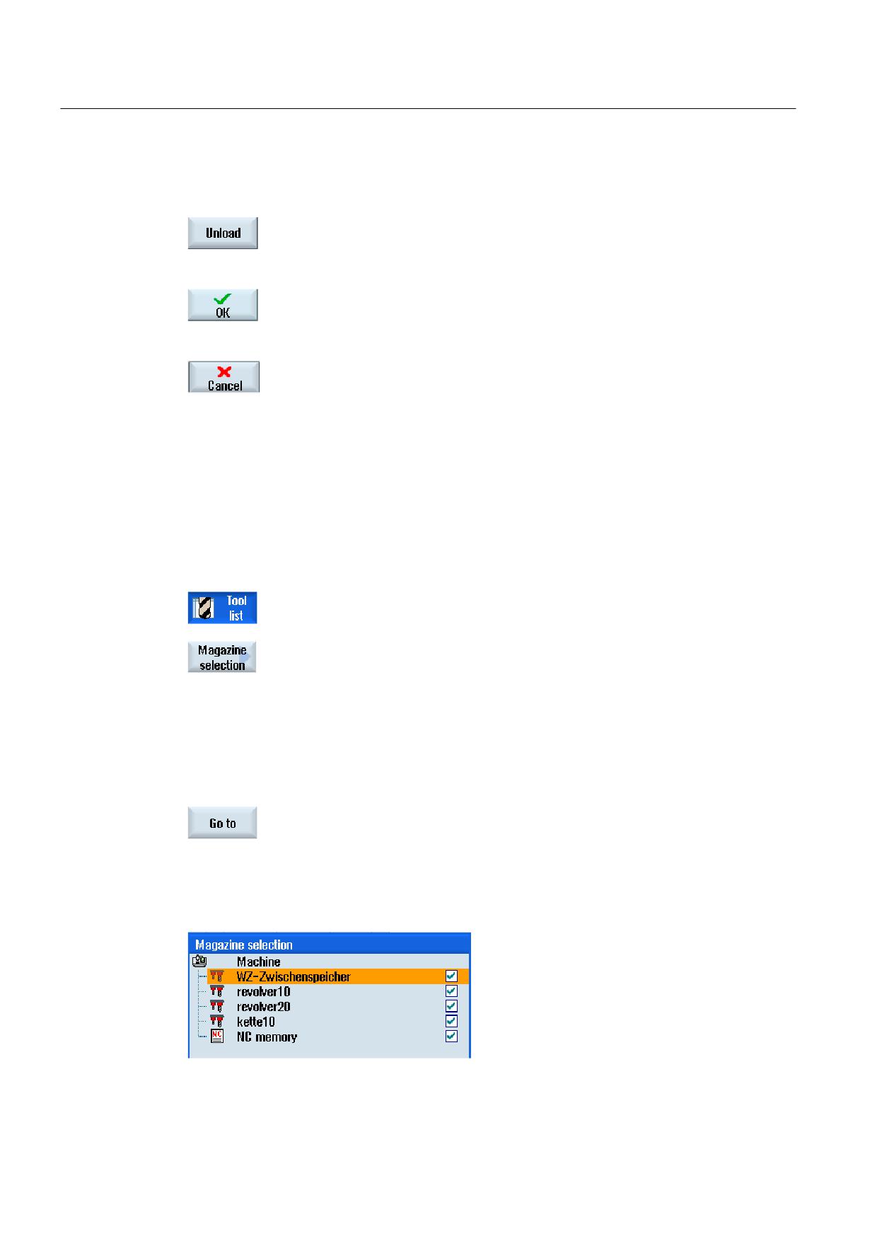
Place the cursor on the tool that you would like to unload from the
magazine and press the "Unload" softkey.
2.
Select the required load point in the "Loading Point Selection" window.
3.
Confirm your selection with "OK".
- OR -
Undo your selection with "Cancel".
8.5.7
Selecting a magazine
You can directly select the buffer memory, the magazine, or the NC memory.
Procedure
1.
The tool list is opened.
2.
Press the "Magazine selection" softkey.
If there is only one magazine, you will move from one area to the next
(i.e. from the buffer memory to the magazine, from the magazine to the
NC memory, and from the NC memory back to the buffer memory) each
time you press the softkey. The cursor is positioned at the beginning of
the magazine each time.
- OR -
If there is more than one magazine, the "Magazine Selection" window
opens. Position the cursor on the desired magazine in this window and
press the "Go to" softkey.
The cursor jumps directly to the beginning of the specified magazine.
Hiding magazines
Universal
200
Operating Manual, 03/2013, 6FC5398-6AP40-3BA1

Tool management
8.5 Tool list
Deactivate the checkbox next to the magazines that you do not want to appear in the
magazine list.
The magazine selection behavior with multiple magazines can be configured in different
ways.
Machine manufacturer
Please refer to the machine manufacturer's specifications.
References
For a description of configuration options, refer to the
Commissioning Manual SINUMERIK Operate / SINUMERIK 840D sl
8.5.8
Code carrier connection (only 840D sl)
You have the option of configuring a connection to MCIS TDI Ident Connection.
This means that the following functions are available in SINUMERIK Operate:
● Creating a new tool from code carrier
● Unloading tools on code carrier
Software option
In order to use the functions, you require the option "MC Information System TDI
Ident Connection".
References
Further details on tool management with code carrier and the configuration of the user
interface in SINUMERIK Operate can be found in the following reference:
● Function Manual MCIS TDI Ident Connection
● Commissioning Manual SINUMERIK Operate (IM9) / SINUMERIK 840D sl
Universal
Operating Manual, 03/2013, 6FC5398-6AP40-3BA1
201
Tool management
8.5 Tool list
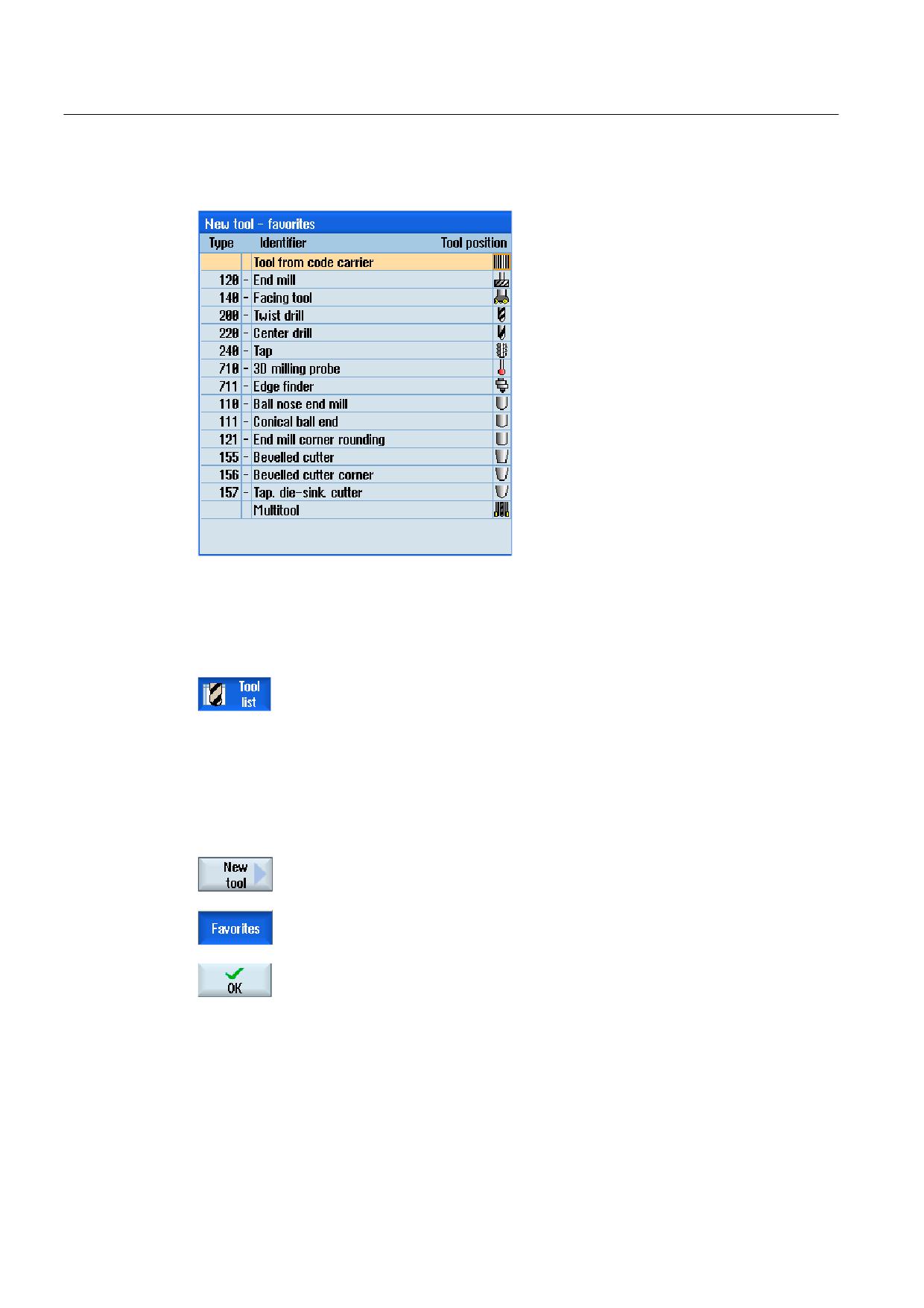
With a code carrier connection, in the list of favorites, there is also a tool available.
Figure 8-18 New tool from code carrier in the list of favorites
Creating a new tool from code carrier
1.
The tool list is opened.
2.
Place the cursor in the tool list at the position where the new tool should
be created.
To do this, you can select an empty magazine location or the NC tool
memory outside of the magazine.
You may also position the cursor on an existing tool in the area of the
NC tool memory. Data from the displayed tool will not be overwritten.
3.
Press the "New tool" softkey.
The "New Tool - Favorites" window is opened.
4.
Position the cursor on the entry "Tool from code carrier" and press the
"OK" softkey.
The tool data is read from the code carrier, and is displayed in the "New
tool" window with the tool type, tool name and possibly with certain
parameters.
Universal
202
Operating Manual, 03/2013, 6FC5398-6AP40-3BA1
Tool management
8.5 Tool list
5.
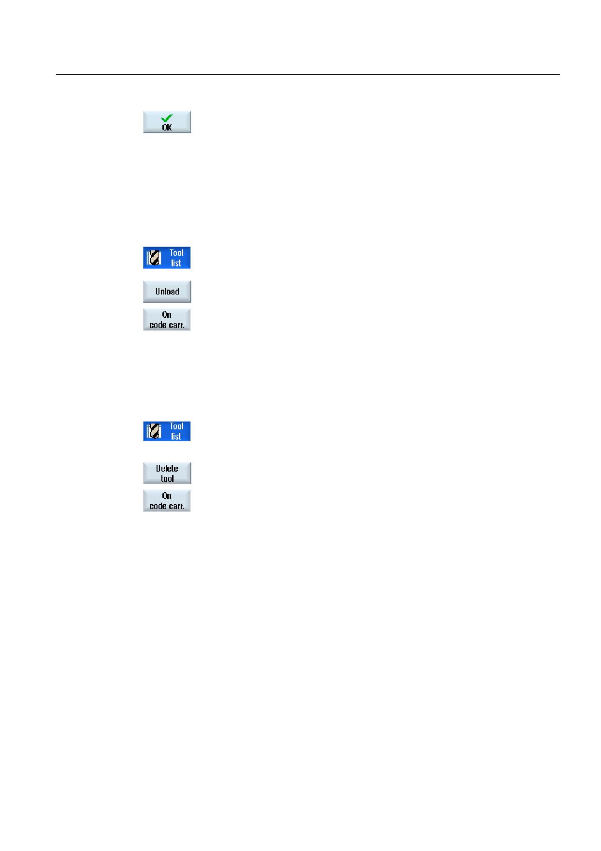
Press the "OK" softkey.
The tool is added to the tool list with the specified name. If the cursor is
located on an empty magazine location in the tool list, then the tool is
loaded to this magazine location.
The tool creation sequence can be defined differently.
Unloading tool on code carrier
1.
The tool list is opened.
2.
Place the cursor on the tool that you would like to unload from the
magazine and press the "Unload" and "On code carrier" softkeys.
The tool is unloaded and the data of the tool are written to the code
carrier.
According to the corresponding setting, the unloaded tool on the code carrier is deleted from
the MC memory after reading out the code carrier.
Deleting tool on code carrier
1.
The tool list is opened.
2.
Position the cursor on the tool on code carrier that you want to delete.
3.
Press the "Delete tool" and "On code carrier" softkeys.
The tool is unloaded and the data of the tool are written to the code
carrier. The tool is then deleted from the NC memory.
The deletion of the tool can be set differently, i.e. the "On code carrier" softkey is not
available.
References
A description of the configuration options can be found in the following reference:
Commissioning Manual SINUMERIK Operate (IM9) / SINUMERIK 840D sl
Universal
Operating Manual, 03/2013, 6FC5398-6AP40-3BA1
203
Tool management
8.6 Tool wear
8.6
Tool wear
All parameters and functions that are required during operation are contained in the tool
wear list.
Tools that are in use for long periods are subject to wear. You can measure this wear and
enter it in the tool wear list. The controller then takes this information into account when
calculating the tool length or radius compensation. This ensures a consistent level of
accuracy during workpiece machining.
Monitoring types
You can automatically monitor the tools' working times via the workpiece count, tool life or
wear.
Note
Combination of monitoring types
You have the option to activate the monitoring of a tool by type or any combination of
monitoring types.
In addition, you can disable tools when you no longer wish to use them.
Machine manufacturer
Please refer to the machine manufacturer's specifications.
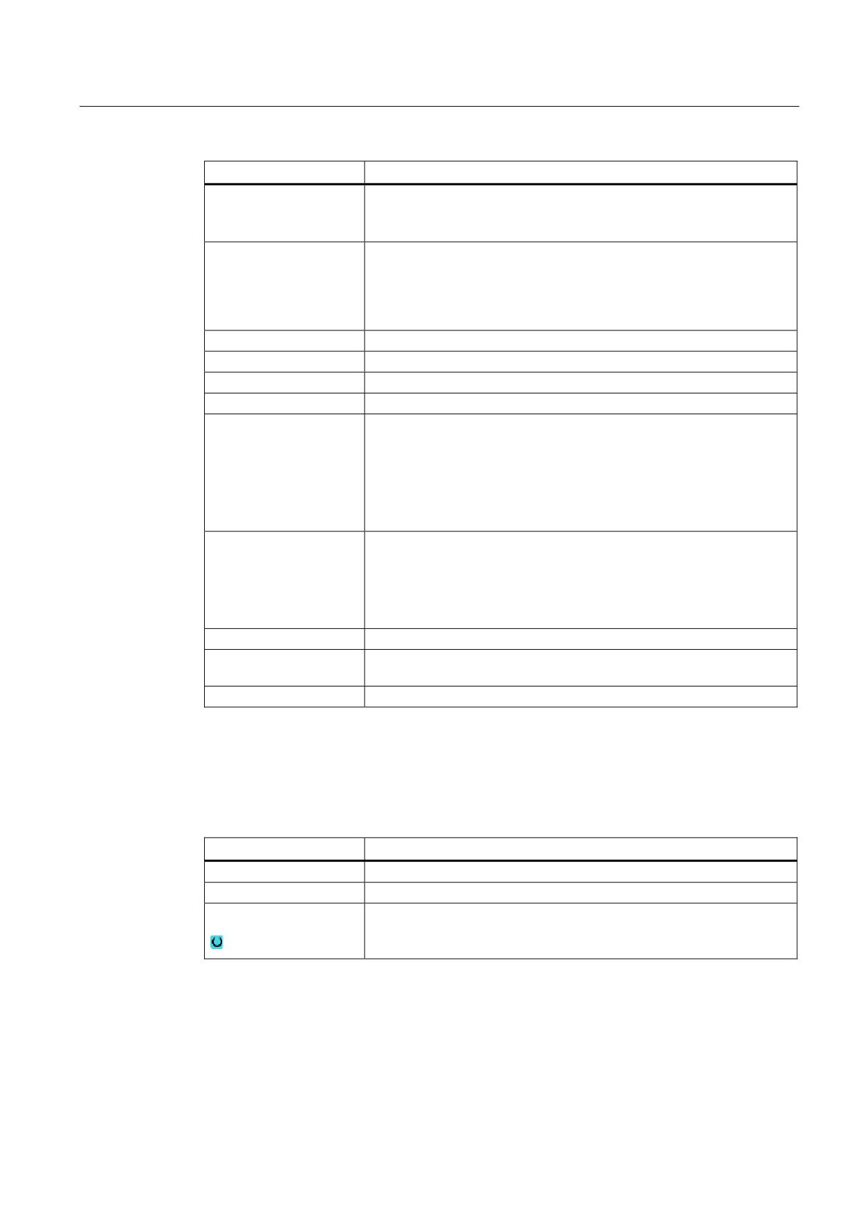
Tool parameters
Column heading
Meaning
Location
Magazine/location number
• The magazine location numbers
The magazine number is specified first, followed by the location
number in the magazine.
If there is only one magazine, only the location number is displayed.
BS
• Load position in the load magazine
The following icons can also be displayed for other magazine types (e.g.
for a chain):
• Spindle location as an icon
• Locations for gripper 1 and gripper 2 (applies only when a spindle
with dual gripper is used) as icons.
* If activated in magazine
selection
Universal
204
Operating Manual, 03/2013, 6FC5398-6AP40-3BA1
Tool management
8.6 Tool wear
Column heading
Meaning
Type
Tool type
Depending on the tool type (represented by an icon), certain tool offset
data is enabled.
Tool name
The tool is identified by the name and the replacement tool number. You
can enter the name as text or number.
Note: The maximum length of tool names is 31 ASCII characters. The
number of characters is reduced for Asian characters or Unicode
characters. The following special characters are not permitted: | # ".
ST
Replacement tool number (for replacement tool strategy).
D
Cutting edge number
Δ Length
Length wear
Δ Radius
Radius wear
T C
Selection of tool monitoring
- by tool life (T)
- by count (C)
- by wear (W)
The wear monitoring is configured via a machine data item.
Please refer to the machine manufacturer's instructions.
Tool life
Tool life
Workpiece count
Number of workpieces
Wear *
Tool wear
*Parameter depends on
selection in TC
Setpoint
Setpoint for tool life, workpiece count, or wear
Prewarning limit
Specification of the tool life, workpiece count or wear at which a warning
is displayed.
G
The tool is disabled when the checkbox is selected.
Further parameters
If you have created unique cutting edge numbers, they will be displayed in the first column.
Column heading
Meaning
D no.
Unique cutting edge number
SN
Cutting edge number
SC
Setting-up offsets
Display of the available setup offsets
Universal
Operating Manual, 03/2013, 6FC5398-6AP40-3BA1
205
Tool management
8.6 Tool wear
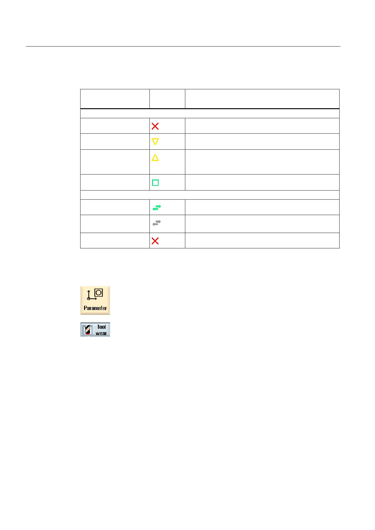
Icons in the wear list
Icon/
Meaning
Marking
Tool type
Red "X"
The tool is disabled.
Yellow triangle pointing
The prewarning limit has been reached.
downward
Yellow triangle pointing
The tool is in a special state.
upward
Place the cursor on the marked tool. A tooltip provides a
short description.
Green border
The tool is preselected.
Magazine/location number
Green double arrow
The magazine location is positioned at the change position.
Gray double arrow
The magazine location is positioned at the loading position.
(configurable)
Red "X"
The magazine location is disabled.
Procedure
1.
Select the "Parameter" operating area.
2.
Press the "Tool wear" softkey.
See also
Changing a tool type (Page 219)
Universal
206
Operating Manual, 03/2013, 6FC5398-6AP40-3BA1
Tool management
8.6 Tool wear
8.6.1
Reactivating a tool
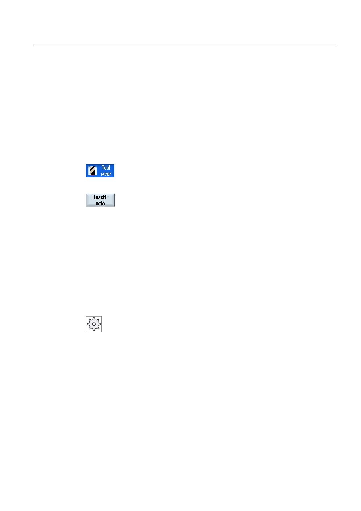
You can replace disabled tools or make them ready for use again.
Preconditions
In order to reactivate a tool, the monitoring function must be activated and a setpoint must be
stored.
Procedure
1.
The tool wear list is opened.
2.
Position the cursor on the disabled tool which you would like to reuse.
3.
Press the "Reactivate" softkey.
The value entered as the setpoint is entered as the new tool life or
workpiece count.
The disabling of the tool is canceled.
Reactivating and positioning
When the "Reactivate with positioning" function is configured, the selected tool's magazine
location will also be positioned at a loading point. You can exchange the tool.
Reactivation of all monitoring types
When the "Reactivation of all monitoring types" function is configured, all the monitoring
types set in the NC for a tool are reset during reactivation.
Machine manufacturer
Please refer to the machine manufacturer's specifications.
References
Commissioning Manual SINUMERIK Operate / SINUMERIK 840D sl
Multiple load points
If you have configured several loading points for a magazine, then the "Loading Point
Selection" window appears after pressing the "Load" softkey.
Select the required load point and confirm with the "OK" softkey.
Universal
Operating Manual, 03/2013, 6FC5398-6AP40-3BA1
207
Tool management
8.7 Tool data OEM
8.7
Tool data OEM
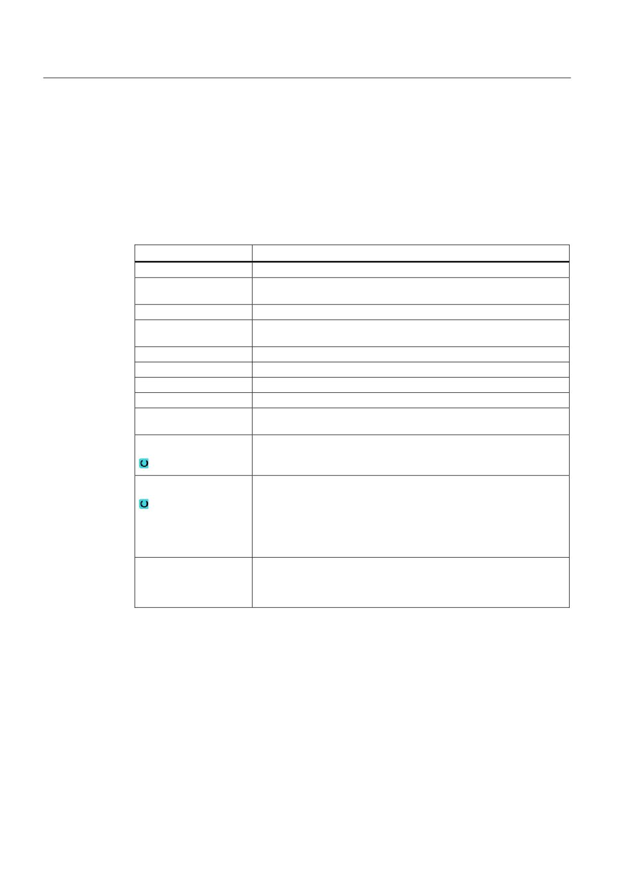
You have the option of configuring the list according to your requirements.
Depending on the machine configuration, grinding-specific parameters are displayed in the
list with OEM tool data.
Grinding tool-specific parameters
Column heading
Meaning
Min. radius
Limit value for the radius of the grinding wheel to monitor the geometry.
Actual radius
Displays the sum of the geometry value, wear value and, if set, the base
dimension.
Min. width
Limit value for the width of the grinding wheel to monitor the geometry.
Actual width
The width of the grinding wheel measured, for example, after the
dressing.
Max. speed
Maximum speed
Max. peripheral velocity
Maximum peripheral velocity
Wheel angle
Angle of inclined wheel
Monitoring
Monitoring geometry and speed
Tool base dimension
Defines whether the base dimension is used when calculating the SUG
and when monitoring the minimum wheel radius.
Spindle number
Number of programmed spindle (e.g. grinding wheel peripheral velocity)
and spindle to be monitored (e.g. wheel radius and width).
Param. rad.calc.
Selects the parameter to calculate the radius
• Length X
• Length Y
• Length Z
• Radius
Chaining rule
This parameter defines which tool parameters of tool cutting edge 2 (D2)
and tool cutting edge 1 (D1) have to be chained to one another. When
the value of a chained parameter is modified, then the other cutting edge
is automatically used when chaining the parameter.
References
You can find more information on grinding tools in the following manual:
Function Manual, Extended Functions W4: Grinding-specific tool offset and monitoring
functions / SINUMERIK 840D sl
Refer to the following document for more information on configuring OEM tool data:
Commissioning Manual SINUMERIK Operate (IM9) / SINUMERIK 840D sl
Universal
208
Operating Manual, 03/2013, 6FC5398-6AP40-3BA1
Tool management
8.8 Magazine
Procedure
1.
Select the "Parameter" operating area.
2.
Press the "OEM tool" softkey.
3.
Position the cursor on a grinding tool.
8.8
Magazine
Tools are displayed with their magazine-related data in the magazine list. Here, you can take
specific actions relating to the magazines and the magazine locations.
Individual magazine locations can be location-coded or disabled for existing tools.
Tool parameters
Column heading
Meaning
Location
Magazine/location number
• The magazine location numbers
The magazine number is specified first, followed by the location
number in the magazine.
If there is only one magazine, only the location number is displayed.
BS
• Load position in the load magazine
The following icons can also be displayed for other magazine types (e.g.
for a chain):
• Spindle location as an icon
• Locations for gripper 1 and gripper 2 (applies only when a spindle
with dual gripper is used) as icons
* If activated in magazine
selection
Type
Tool type
Depending on the tool type (represented by an icon), certain tool offset
data is enabled.
Tool name
The tool is identified by the name and the replacement tool number. You
can enter the name as text or number.
Note: The maximum length of tool names is 31 ASCII characters. The
number of characters is reduced for Asian characters or Unicode
characters. The following special characters are not permitted: | # ".
Universal
Operating Manual, 03/2013, 6FC5398-6AP40-3BA1
209
Tool management
8.8 Magazine
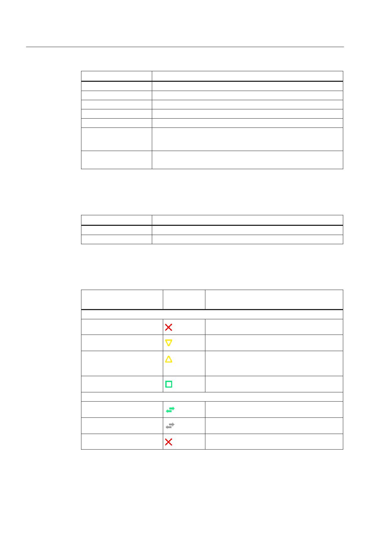
Column heading
Meaning
ST
Replacement tool number (for replacement tool strategy).
D
Cutting edge number
G
Disabling of the magazine location.
Mag.loc. type
Display of magazine location type.
Tool.loc. type
Display of tool location type.
Ü
Marking of a tool as oversized. The tool occupies two half locations left,
two half locations right, one half location top and one half location bottom
in a magazine.
P
Fixed location coding.
The tool is permanently assigned to this magazine location.
Further parameters
If you have created unique cutting edge numbers, they will be displayed in the first column.
Column heading
Meaning
D no.
Unique cutting edge number
SN
Cutting edge number
Magazine list icons
Icon/
Meaning
Marking
Tool type
Red "X"
The tool is disabled.
Yellow triangle pointing
The prewarning limit has been reached.
downward
Yellow triangle pointing
The tool is in a special state.
upward
Place the cursor on the marked tool. A tooltip
provides a short description.
Green border
The tool is preselected.
Magazine/location number
Green double arrow
The magazine location is positioned at the change
position.
Gray double arrow
The magazine location is positioned at the loading
(configurable)
position.
Red "X"
The magazine location is disabled.
Universal
210
Operating Manual, 03/2013, 6FC5398-6AP40-3BA1
Tool management
8.8 Magazine
Procedure
1.
Select the "Parameter" operating area.
2.
Press the "Magazine” softkey.
See also
Changing a tool type (Page 219)
8.8.1
Position magazine
You can position magazine locations directly on the loading point.
Procedure
1.
The magazine list is opened.
2.
Place the cursor on the magazine location that you want to position
onto the load point.
3.
Press the "Position magazine" softkey.
The magazine location is positioned on the loading point.
Multiple load points
If you have configured several loading points for a magazine, then the "Loading Point
Selection" window appears after pressing the "Position magazine" softkey.
Select the desired loading point in this window and confirm your selection with "OK" to
position the magazine location at the loading point.
Universal
Operating Manual, 03/2013, 6FC5398-6AP40-3BA1
211
Tool management
8.8 Magazine
8.8.2
Relocating a tool
Tools can be directly relocated within magazines to another magazine location, which means
that you do not have to unload tools from the magazine in order to load them into a different
location.
When you are relocating a tool, the application automatically suggests an empty location.
You may also directly specify an empty magazine location.
Buffer
You have the option of relocating the tool to buffer locations.
Machine manufacturer
Please refer to the machine manufacturer's specifications.
Procedure
1.
The magazine list is opened.
2.
Position the cursor on the tool that you wish to relocate to a different
magazine location.
3.
Press the "Relocate" softkey.
The "... relocate from location ... to location ..." window is displayed. The
"Location" field is pre-assigned with the number of the first empty
magazine location.
4.
Press the "OK" softkey to relocate the tool to the recommended
magazine location.
- OR -
Enter the required magazine, enter the location number and press the
"OK" softkey.
- OR -
Enter the number "9998" or the number "9999" into the "... magazine"
field in order to select the buffer as well as the required buffer location
in the "Location" field.
- OR -
Press the "Spindle" softkey to load a tool into the spindle and press the
"OK" softkey.
The tool is relocated to the specified magazine location, in the spindle
or in the buffer.
Universal
212
Operating Manual, 03/2013, 6FC5398-6AP40-3BA1
Tool management
8.8 Magazine
Several magazines
If you have set up several magazines, then the "...relocate from magazine... location... to..."
window appears after pressing the "Relocate" softkey.
Select the desired magazine and location, and confirm your selection with "OK" to load the
tool.
8.8.3
Unload all tools
You have the option of unloading all tools from the magazine list. A single request
successively unloads the tools from the list.
Requirement
The following requirements must be satisfied so that the "Unload all" softkey is displayed and
available:
● Magazine management is set up
● There is no tool in the buffer / in the spindle
Machine manufacturer
Please refer to the machine manufacturer's specifications.
Procedure
1.
The magazine list is opened.
2.
Press the "Unload all" softkey.
A prompt is displayed as to whether you really want to unload all tools.
3.
Press the "OK" softkey to continue with the unloading of the tools.
The tools are unloaded from the magazine in ascending magazine
location number order.
4.
Press the "Cancel" softkey if you wish to cancel the unloading operation.
Multiple load points
For a magazine, if more than one loading point was set-up, using the "Select loading point"
softkey, you have the option of opening a window in which you can assign a loading point to
a magazine.
Universal
Operating Manual, 03/2013, 6FC5398-6AP40-3BA1
213
Tool management
8.9 Sorting tool management lists
8.9
Sorting tool management lists
When you are working with many tools, with large magazines or several magazines, it is
useful to display the tools sorted according to different criteria. Then you will be able to find a
specific tool more easily in the lists.
Procedure
1.
Select the "Parameter" operating area.
2.
Press the "Tool list", "Tool wear" or "Magazine" softkey.
3.
Press the ">>" and "Sort" softkeys.
The lists are displayed sorted numerically according to magazine
location.
Tool types are used to sort tools with the same magazine location.
Identical types (e.g. milling cutters), in turn, are sorted according to their
radius value.
4.
Press the "Acc. to type" softkey to display the tools arranged by tool
type. Identical types (e.g. milling cutters) are sorted according to their
radius value.
- OR -
Press the "Acc. to name" softkey to display the tool names in
alphabetical order.
The replacement tool numbers are used to sort tools with the same
names.
- OR -
Press the "Acc. to T number" softkey to display the tool names sorted
numerically.
- OR -
Press the "Acc. to D number" softkey to display the tools sorted by D
number.
The list is sorted according to the specified criteria.
Universal
214
Operating Manual, 03/2013, 6FC5398-6AP40-3BA1

Tool management
8.10 Filtering the tool management lists
Machine manufacturer
Please refer to the machine manufacturer's specifications.
8.10
Filtering the tool management lists
The filter function allows you to filter-out tools with specific properties in the tool
management lists.
For instance, you have the option of displaying tools during machining that have already
reached the prewarning limit in order to prepare the corresponding tools to be loaded.
Filter criteria
● Only display the first cutting edge
● Only tools that are ready to use
● Only tools that have reached the prewarning limit
● Only tools with active code
● Only locked tools
● Only tools with remaining quantity of ... to ...
● Only tools with residual tool life of ... to ...
● Only tools with unloading marking
● Only tools with loading marking
Machine manufacturer
Please refer to the machine manufacturer's specifications.
Note
Multiple selection
You have the option of selecting several criteria. You will receive an appropriate message if
conflicting filter options are selected.
You can configure OR logic operations for the various filter criteria.
References
A description of the configuration options is provided in
SINUMERIK Operate (IM9) / SINUMERIK 840D sl Commissioning Manual
Universal
Operating Manual, 03/2013, 6FC5398-6AP40-3BA1
215
Tool management
8.11 Specific search in the tool management lists
Procedure
1.
Select the "Parameter" operating area.
2.
Press the "Tool list", "Tool wear" or "Magazine" softkey.
3.
Press the ">>" and "Filter" softkeys.
The "Filter" window opens.
4.
Activate the required filter criterion and press the "OK" softkey.
The tools that correspond to the selection criteria are displayed in the
list.
The active filter is displayed in the window header.
8.11
Specific search in the tool management lists
There is a search function in all tool management lists, where you can search for the
following objects:
● Tools
- You enter a tool name. You can narrow down your search by entering a replacement
tool number.
You have the option of only entering a part of the name as search term.
- Enter the D number and, if necessary, activate the "Active D number" checkbox.
● Magazine locations or magazines
If only one magazine is configured, then the search is only made for the magazine
location.
If several magazines are configured, then it is possible to search a specific magazine
location in a specific magazine or just to search in a specific magazine.
● Empty locations
If the lists with the location type are used, then the empty location search is made using
the location type and location size.
Universal
216
Operating Manual, 03/2013, 6FC5398-6AP40-3BA1
Tool management
8.11 Specific search in the tool management lists
Machine manufacturer
Please refer to the machine manufacturer's specifications.
Procedure
1.
Select the "Parameter" operating area.
2.
Press the "Tool list", "Tool wear" or "Magazine" softkey.
3.
Press the ">>" and "Search" softkeys.
4.
Press the "Tool" softkey if you wish to search for a specific tool.
- OR -
Press the "Magazine location" softkey if you wish to search for a
specific magazine location or a specific magazine.
- OR -
Press the "Empty location" softkey if you wish to search for a specific
empty location.
Universal
Operating Manual, 03/2013, 6FC5398-6AP40-3BA1
217
Tool management
8.12 Displaying tool details
8.12
Displaying tool details
All of the parameters of the selected tool are listed in the "Tool Details - All Parameters"
window.
The parameters are displayed, sorted according to the following criteria
● Tool data
● Grinding data (if grinding tools have been configured)
● Cutting edge data
● Monitoring data
Protection level
You require access level, key switch 3 (protection level 4) in order to edit the parameters in
the detail window.
Machine manufacturer
Please refer to the machine manufacturer's specifications.
Procedure
1.
The tool list, the wear list, the OEM tool list or the magazine is opened.
2.
Position the cursor to the desired tool.
3.
If you are in the tool list or in the magazine, press the ">>" and "Details"
softkey.
- OR -
If you are in the wear list or OEM tool list, press the "Details" softkey.
The "Tool Details" window is displayed.
All of the available tool data is displayed in the list.
4.
Press the "Grinding data" softkey if you want to display the grinding
data.
5.
Press the softkey "Cutting edge data" if you wish to display the cutting
edge data.
Universal
218
Operating Manual, 03/2013, 6FC5398-6AP40-3BA1
Tool management
8.13 Changing a tool type
6.
Press the softkey "Monitoring data" if you wish to display the monitoring
data.
7.
Press the "Additional details" softkey.
The "Tool Details - All Parameters" window is opened.
All of the tool parameters are displayed in the list.
8.13
Changing a tool type
Procedure
1.
The tool list, the wear list, the OEM tool list or the magazine is opened.
2.
Position the cursor in the column "Type" of the tool that you wish to
change.
3.
Press the <SELECT> key.
The "Tool types - Favorites" window opens.
4.
Select the desired tool type in the list of favorites or select using the
softkeys "Cutters 100-199", "Drill 200-299", "Grinders 400-499" or "
Spec.tool 700-900".
Note: A grinding tool can only be changed into another grinding tool
type.
5.
Press the "OK" softkey.
The new tool type is accepted and the corresponding icon is displayed
in the "Type" column.
Universal
Operating Manual, 03/2013, 6FC5398-6AP40-3BA1
219
Tool management
8.14 Settings for tool lists
8.14
Settings for tool lists
The "Settings" window provides the following options to set the view in the tool lists:
● Display only one magazine in the magazine sorting
- You limit the display to one magazine. The magazine is displayed with the assigned
buffer locations and the not-loaded tools.
- You use a configuration to specify whether the "Magazine selection" softkey jumps to
the next magazine or whether the "Magazine Selection" dialog for changing switches
to any magazine.
● Display only spindles in the buffer
In order to display during operation only the spindle location, the remaining locations of
the buffer will be hidden.
● Activating the adapter-transformed view
- The geometry lengths and the operation offsets are displayed transformed in the tool
list.
- The wear lengths and the sum offsets are displayed transformed in the tool wear list.
Machine manufacturer
Please refer to the machine manufacturer's specifications.
References
Further information about configuring the settings are shown in the following reference:
SINUMERIK Operate (IM9) / SINUMERIK 840D sl Commissioning Manual
Universal
220
Operating Manual, 03/2013, 6FC5398-6AP40-3BA1
Tool management
8.14 Settings for tool lists
Procedure
1.
Select the "Parameter" operating area.
2.
Press the "Tool list", "Tool wear" or "Magazine" softkey.
3.
Press the "Continue" and "Settings" softkeys.
4.
Activate the checkbox for the desired setting.
Universal
Operating Manual, 03/2013, 6FC5398-6AP40-3BA1
221
Tool management
8.14 Settings for tool lists
Universal
222
Operating Manual, 03/2013, 6FC5398-6AP40-3BA1
Managing programs
9
9.1
Overview
You can access programs at any time via the Program Manager for execution, editing,
copying, or renaming.
Programs that you no longer require can be deleted to release their storage space.
NOTICE
Possible interruption when executing from USB FlashDrive
Direct execution from a USB-FlashDrive is not recommended.
There is no protection against contact problems, falling out, breakage through knocking or
unintentional removal of the USB-FlashDrive during operation.
Disconnecting it during operation will result in the stopping of the machining and thus to the
workpiece being damaged.
Multiple clamping with ShopMill
With ShopMill, you can implement multiple clamping of identical or different workpieces with
optimization of the tool series.
Software options
Multiple clamping is only possible with ShopMill programs. You require the
"ShopTurn/ShopMill" option for this.
Storage for programs
Possible storage locations are:
● NC
● Local drive
● Network drives
● USB drives
● V24
● FTP drives
Universal
Operating Manual, 03/2013, 6FC5398-6AP40-3BA1
223
Managing programs
9.1 Overview
Software options
To display the "Local drive" softkey, you require the "Additional HMI user
memory on CF card of the NCU" option (not for SINUMERIK Operate on
PCU50 or PC/PG).
Data exchange with other workstations
You have the following options for exchanging programs and data with other workstations:
● USB drives (e.g. USB-FlashDrive)
● Network drives
● FTP drive
Choosing storage locations
In the horizontal softkey bar, you can select the storage location that contains the directories
and programs that you want to display. In addition to the "NC" softkey, via which the passive
file system data can be displayed, additional softkeys can be displayed.
The "USB" softkey is only operational when an external storage medium is connected (e.g.
USB-FlashDrive on the USB port of the operator panel).
Displaying PDF and HTML documents
You can display HTML documents as well as PDFs on drives of the program manager (e.g.
in the local drive or USB) and via the data tree of the system data.
However, a preview of the documents is only possible for PDFs.
Note
FTP drive
It is not possible to preview documents on the FTP drive.
Universal
224
Operating Manual, 03/2013, 6FC5398-6AP40-3BA1
Managing programs
9.1 Overview
Structure of the directories
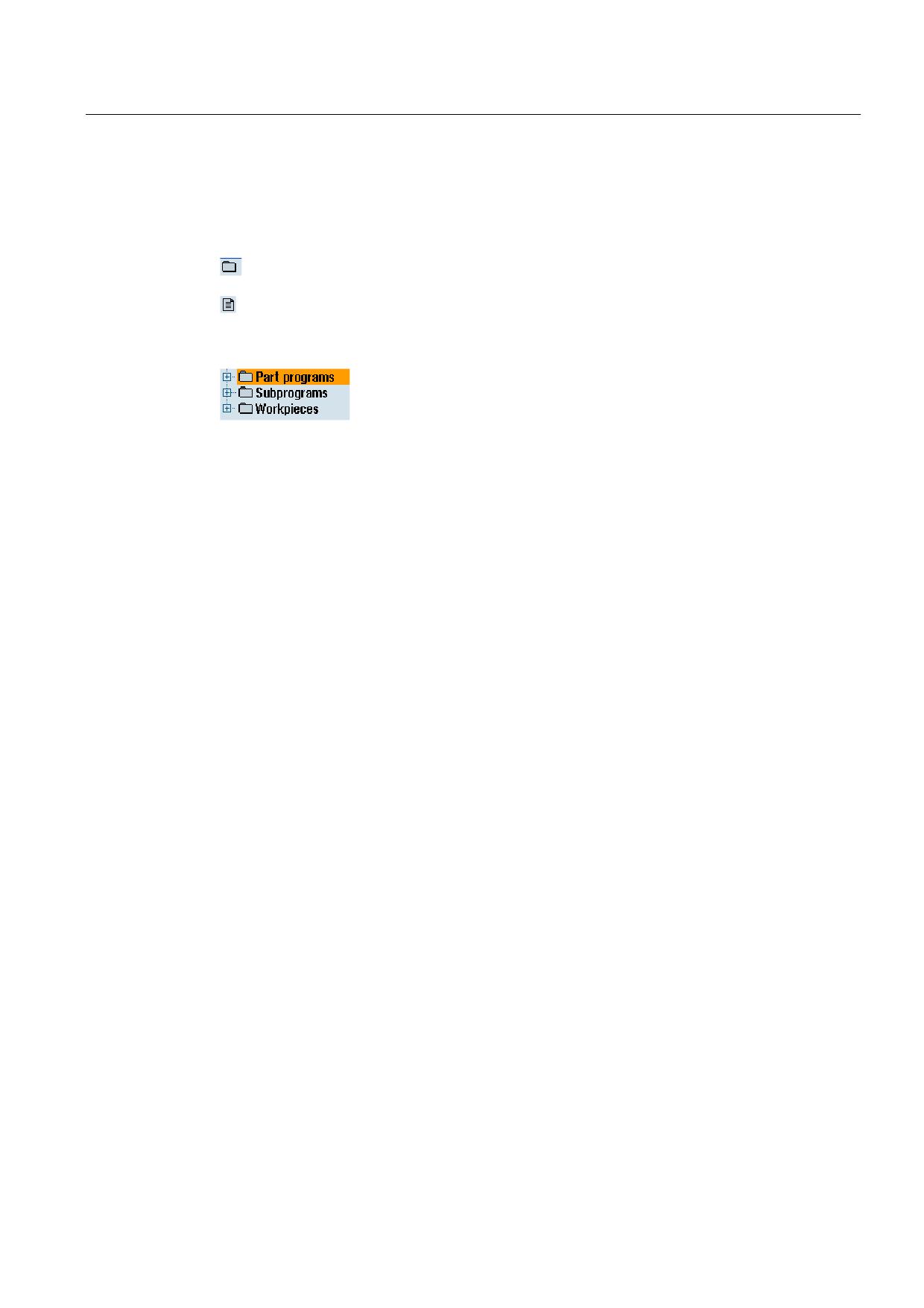
In the overview, the symbols in the left-hand column have the following meaning:
Directory
Program
All directories have a plus sign when the program manager is called for the first time.
Figure 9-1
Program directory in the program manager
The plus sign in front of empty directories is removed after they have been read for the first
time.
The directories and programs are always listed complete with the following information:
● Name
The name can be a maximum of 24 characters long
Permissible characters include all upper-case letters (without accents), numbers, and
underscores.
● Type
Directory: WPD
Program: MPF
Subprogram: SPF
Initialization programs: INI
Job lists: JOB
Tool data: TOA
Magazine assignment: TMA
Zero points: UFR
R parameters: RPA
Global user data/definitions: GUD
Setting data: SEA
Protection zones: PRO
Sag: CEC
● Size (in bytes)
● Date/time (of creation or last change)
Universal
Operating Manual, 03/2013, 6FC5398-6AP40-3BA1
225
Managing programs
9.1 Overview
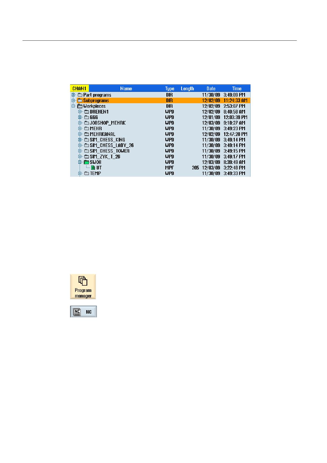
Active programs
Selected, i.e. active programs are identified using a green symbol.
Figure 9-2
Active program shown in green
9.1.1
NC memory
The complete NC working memory is displayed along with all tools and the main programs
and subroutines.
You can create further subdirectories here.
Proceed as follows
1.
Select the "Program manager" operating area.
2.
Press the "NC" softkey.
Universal
226
Operating Manual, 03/2013, 6FC5398-6AP40-3BA1
Managing programs
9.1 Overview
9.1.2
Local drive
Workpieces, main and subprograms that are saved in the user memory of the CF card or on
the local hard disk are displayed.
For archiving, you have the option of mapping the structure of the NC memory system or to
create a separate archiving system.
You can create any number of subdirectories here, in which you can store any files (e.g. text
files with notes).
Software options
To display the "Local drive" softkey, you require the "Additional HMI user
memory on CF card of the NCU" option (not for SINUMERIK Operate on
PCU50 or PC/PG).
Procedure
1.
Select the "Program manager" operating area.
2.
Press the "Local drive" softkey.
On the local drive, you have the option of mapping the directory structure of the NC memory.
This also simplifies the search sequence.
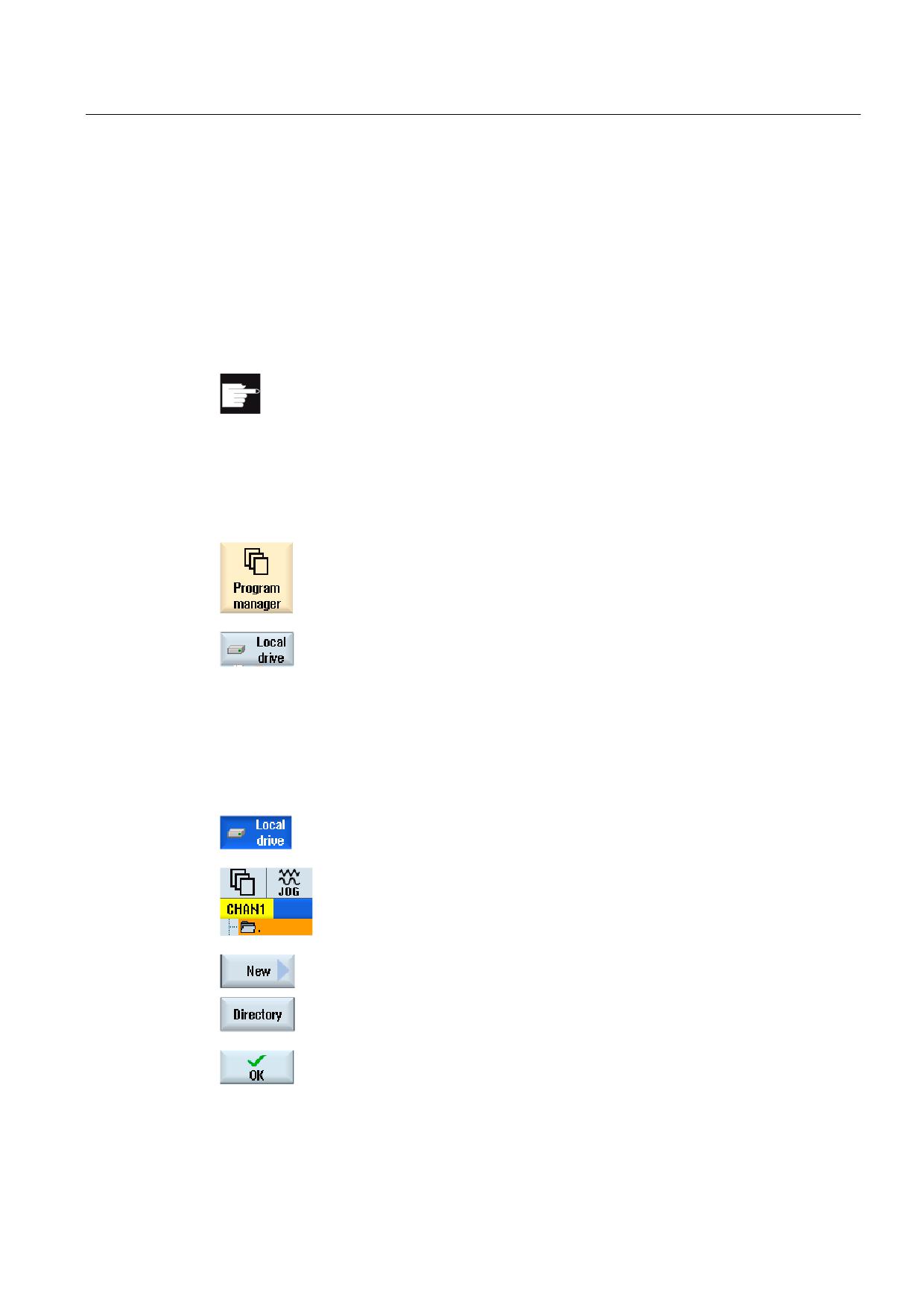
Creating Directories
1.
The local drive is selected.
2.
Position the cursor on the main directory.
3.
Press the "New" and "Directory" softkeys.
The "New Directory" window opens.
4.
In the "Name" entry field, enter "mpf.dir", "spf.dir" and "wks.dir" and
press the "OK" softkey.
The directories "Part programs", "Subprograms" and "Workpieces" are
created below the main directory.
Universal
Operating Manual, 03/2013, 6FC5398-6AP40-3BA1
227
Managing programs
9.1 Overview
9.1.3
USB drives
USB drives enable you to exchange data. For example, you can copy to the NC and execute
programs that were created externally.
NOTICE
Interruption of operation
Direct execution from the USB FlashDrive is not recommended, because machining can be
undesirably interrupted, therefore resulting in workpiece damage.
Partitioned USB-FlashDrive (only 840D sl and TCU)
If the USB-FlashDrive has several partitions, these are displayed in a tree structure as a
subtree (01,02,...).
For EXTCALL calls, enter the partition (e.g. USB:/02/... or //ACTTCU/FRONT/02/... or
//ACTTCU/FRONT,2/... or //TCU/TCU1/FRONT/02/...)
You can also configure any partition (e.g. //ACTTCU/FRONT,3).
Procedure
1.
Select the "Program manager" operating area.
2.
Press the "USB" softkey.
Note
The "USB" softkey can only be operated when a USB-FlashDrive is inserted in the front
interface of the operator panel.
Universal
228
Operating Manual, 03/2013, 6FC5398-6AP40-3BA1
Managing programs
9.1 Overview
9.1.4
FTP drive
The FTP drive offers you the following options - to transfer data, e.g. part programs, between
your control system and an external FTP server.
You have the option of archiving any files in the FTP server by creating new directories and
subdirectories.
Note
Selecting a program / execution
It is not possible to select a program directly on the FTP drive, and change to execution in
the "Machine" operating area.
Precondition
User name and password have been set up in the FTP server.
Procedure
1.
Select the "Program manager" operating area.
2.
Press the "FTP" softkey.
When selecting the FTP drive for the first time, a login window is
displayed.
3.
Enter the user name and password and press the "OK" softkey to log
into the FTP server.
The content of the FTP server with its folders is displayed.
4.
Press the "Log out" softkey after the required data processing has been
completed.
The connection to the FTP server is disconnected. In order to reselect
the FTP drive, you must log on again.
Universal
Operating Manual, 03/2013, 6FC5398-6AP40-3BA1
229
Managing programs
9.2 Opening and closing a program
9.2
Opening and closing a program
To view a program in more detail or modify it, open the program in the editor.
With programs that are in the NCK memory, navigation is already possible when opening.
The program blocks can only be edited when the program has been opened completely. You
can follow the opening of the program in the dialog line.
With programs that are opened via local network, USB FlashDrive or network connections,
navigation is only possible when the program has been opened completely. A progress
message box is displayed when opening the program.
Note
Channel changeover in the editor
When opening the program, the editor is opened for the currently selected channel. This
channel is used to simulate the program.
If you change over a channel in the editor, this does not influence the editor. Only when
closing the editor do you change into the other channel.
Procedure
1.
Select the "Program manager" operating area.
2.
Select the desired storage location and position the cursor on the
program that you would like to edit.
3.
Press the "Open" softkey.
- OR -
Press the <INPUT> key.
- OR -
Press the <Cursor right> key.
- OR -
Double-click the program.
The selected program is opened in the "Editor" operating area.
4.
Now make the necessary program changes.
Universal
230
Operating Manual, 03/2013, 6FC5398-6AP40-3BA1
Managing programs
9.2 Opening and closing a program
5.
Press the "NC Select" softkey to switch to the "Machine" operating area
and begin execution.
When the program is running, the softkey is deactivated.
Closing the program
Press the ">>" and "Exit" softkeys to close the program and editor again.
- OR -
If you are at the start of the first line of the program, press the <Cursor left>
key to close the program and the editor.
To reopen a program you have exited with "Close", press the "Program" key.
Note
A program does not have to be closed in order for it to be executed.
Universal
Operating Manual, 03/2013, 6FC5398-6AP40-3BA1
231
Managing programs
9.3 Executing a program
9.3
Executing a program
When you select a program for execution, the controller automatically switches to the
"Machine" operating area.
Program selection
Select the workpieces (WPD), main programs (MPF) or subprograms (SPF) by placing the
cursor on the desired program or workpiece.
For workpieces, the workpiece directory must contain a program with the same name. This
program is automatically selected for execution (e.g. when you select the workpiece
SHAFT.WPD, the main program SHAFT.MPF is automatically selected).
If an INI file of the same name exists (e.g. SHAFT.INI), it will be executed once at the first
part program start after selection of the part program. Any additional INI files are executed in
accordance with machine data MD11280 $MN_WPD_INI_MODE.
MD11280 $MN_WPD_INI_MODE=0:
The INI file with the same name as the selected workpiece is executed. For example, when
you select SHAFT1.MPF, the SHAFT1.INI file is executed upon <CYCLE START>.
MD11280 $MN_WPD_INI_MODE=1:
All files of type SEA, GUD, RPA, UFR, PRO, TOA, TMA and CEC which have the same
name as the selected main program are executed in the specified sequence. The main
programs stored in a workpiece directory can be selected and processed by several
channels.
Machine manufacturer
Please refer to the machine manufacturer's specifications.
Procedure
1.
Select the "Program Manager" operating area.
2.
Select the desired storage location and position the cursor on the
workpiece/program that you would like to execute.
3.
Press the "Select" softkey.
The controller switches automatically into the "Machine" operating area.
- OR -
Universal
232
Operating Manual, 03/2013, 6FC5398-6AP40-3BA1
Managing programs
9.4 Creating a directory/program/job list/program list
If the selected program is already opened in the "Program" operating
area,
Press the "Execute NC" softkey.
Press the <CYCLE START> key.
Execution of the workpiece is started.
Note
Only workpieces/programs that are located in the NCK memory, local drive or USB drive can
be selected for execution.
9.4
Creating a directory/program/job list/program list
9.4.1
Creating a new directory
Directory structures help you to manage your program and data transparently. You can
create subdirectories in a directory on the local drive and on USB/network drives.
In a subdirectory, in turn, you can create programs and then create program blocks for them.
Note
Directory names must end in .DIR or .WPD. The maximum name length is 49 characters
including the extension.
All letters (except accented characters), numbers, and underscores are permitted for name
assignment. These names are automatically converted to upper-case letters.
This limitation does not apply for work on USB/network drives.
Universal
Operating Manual, 03/2013, 6FC5398-6AP40-3BA1
233
Managing programs
9.4 Creating a directory/program/job list/program list
Procedure
1.
Select the "Program manager" operating area.
2.
Select your chosen storage medium, i.e. a local or USB drive.
3.
If you want to create a new directory in the local network, place the
cursor on the topmost folder and press the "New" and "Directory"
softkeys.
The "New Directory" window opens.
4.
Enter the desired directory name and press the "OK" softkey.
9.4.2
Creating a new workpiece
You can set up various types of files such as main programs, initialization files, tool offsets,
etc. in a workpiece.
Note
Workpiece directories
You have the option of nesting tool directories. You must note that the length of the call line
is restricted. You will be informed if the maximum number of characters is reached when
entering the workpiece name
Procedure
1.
Select the "Program manager" operating area.
2.
Select the desired storage location and position the cursor on the folder,
in which you would like to create a workpiece.
3.
Press the "New" softkey.
The "New Workpiece" window appears.
Universal
234
Operating Manual, 03/2013, 6FC5398-6AP40-3BA1
Managing programs
9.4 Creating a directory/program/job list/program list
4.
If necessary, select a template if any are available.
5.
Enter the desired workpiece name and press the "OK" softkey.
The name can be a maximum of 24 characters long.
You can use any letters (except accented), digits or the underscore
symbol (_).
The directory type (WPD) is set by default.
A new folder with the workpiece name will be created.
The "New G Code Program" window will open.
6.
Press the "OK" softkey again if you want to create the program.
The program will open in the editor.
See also
Storing any new file (Page 236)
9.4.3
Creating a new G code program
You can create G code programs and then render G code blocks for them in a
directory/workpiece.
Procedure
1.
Select the "Program manager" operating area.
2.
Select the desired storage location and position the cursor on the folder,
in which you would like to store the program.
3.
Press the "New" softkey.
The "New G Code Program" window appears.
4.
If necessary, select a template if any are available.
5.
Select the file type (MPF or SPF).
If you are in the NC memory and have selected the file "Subprograms"
or "Part programs", you can create only one subprogram (SPF) or main
program (MPF) respectively.
Universal
Operating Manual, 03/2013, 6FC5398-6AP40-3BA1
235
Managing programs
9.4 Creating a directory/program/job list/program list
6.
Enter the desired program name and press the "OK" softkey.
Program names may be a maximum of 24 characters in length.
You can use all letters (with the exception of special characters,
language-specific special characters, Asian or Cyrillic characters),
numbers and underscores (_). The program type is appropriately
specified.
9.4.4
Storing any new file
In each directory or subdirectory you can create a file in any format that you specify.
Note
File extensions
In the NC memory, the extension must have 3 characters, and DIR or WPD are not
permitted.
In the NC memory, you can create the following file types under a workpiece using the "Any"
softkey.
Universal
236
Operating Manual, 03/2013, 6FC5398-6AP40-3BA1
Managing programs
9.4 Creating a directory/program/job list/program list
Procedure
1.
Select the "Program manager" operating area.
2.
Select the desired storage location and position the cursor on the folder
in which you would like to create the file.
3.
Press the "New" and "Any" softkeys.
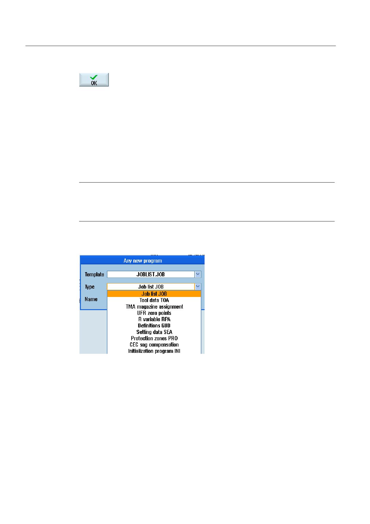
The "Any New Program" window appears
4.
Select a file type from the "Type" selection field (for example,
"Definitions GUD") and enter the name of the file to be created when
you have selected a workpiece directory in the NC memory.
The file automatically has the selected file format.
- OR -
Enter a name and file format for the file to be created (e.g. My_Text.txt).
The name can be a maximum of 24 characters long.
You can use any letters (except accented), digits or the underscore
symbol (_).
5.
Press the "OK" softkey.
Universal
Operating Manual, 03/2013, 6FC5398-6AP40-3BA1
237
Managing programs
9.4 Creating a directory/program/job list/program list
9.4.5
Creating a job list
For every workpiece, you can create a job list for extended workpiece selection.
In the job list, you specify instructions for program selection in different channels.
Syntax
The job list contains the SELECT instructions.
SELECT <program> CH=<channel number> [DISK]
The SELECT instruction selects a program for execution in a specific NC channel. The
selected program must be loaded into the working memory of the NC. The DISK parameter
enables the selection of external execution (CF card, USB data carrier, network drive).
● <Program>
Absolute or relative path specification of the program to be selected.
Examples:
-
//NC/WCS.DIR/SHAFT.WPD/SHAFT1.MPF
– SHAFT2.MPF
● <Channel number>
Number of the NC channel in which the program is to be selected.
Example:
CH=2
● [DISK]
Optional parameter for programs that are not in the NC memory and are to be executed
"externally".
Example:
SELECT //remote/myshare/shaft3.mpf CH=1 DISK
Comment
Comments are identified in the job list by ";" at the start of the line or by round brackets.
Template
You can select a template from Siemens or the machine manufacturer when creating a new
job list.
Universal
238
Operating Manual, 03/2013, 6FC5398-6AP40-3BA1
Managing programs
9.4 Creating a directory/program/job list/program list
Executing a workpiece
If the "Select" softkey is selected for a workpiece, the syntax of the associated job list is
checked and then executed. The cursor can also be placed on the job list for selection.
Procedure
1.
Select the "Program manager" operating area.
2.
Press the "NC" softkey, and in directory "Workpieces" place the cursor
on the program for which you wish to create a job list.
3.
Press the "New" and "Any" softkeys.
The "Any New Program" window opens.
4.
Select entry "Job list JOB" from the "Type" selection field and enter a
name and press the "OK" softkey.
9.4.6
Creating a program list
You can also enter programs in a program list that are then selected and executed from the
PLC.
The program list may contain up to 100 entries.
Machine manufacturer
Please refer to the machine manufacturer's specifications.
Procedure
1.
Select the "Program manager" operating area.
2.
Press the menu forward key and the "Program list" softkey.
The "Prog.-list" window opens.
Universal
Operating Manual, 03/2013, 6FC5398-6AP40-3BA1
239
Managing programs
9.4 Creating a directory/program/job list/program list
3.
Place the cursor in the desired line (program number).
4.
Press the "Select program" softkey.
The "Programs" window opens. The data tree of the NC memory with
workpiece, part program and subprogram directory is displayed.
5.
Place the cursor on the desired program and press the "OK" softkey.
The selected program is inserted in the first line of the list together with
its path.
- OR -
Enter the program name directly in the list.
If you are making entries manually, check that the path is correct (e.g.
//NC/WKS.DIR/MEINPROGRAMM.WPD/MEINPROGRAMM.MPF).
//NC and the extension (.MPF) may be added automatically.
With multi-channel machines, you can specify in which channel the
program is to be selected.
6.
To remove a program from the list, place the cursor on the appropriate
line and press the "Delete" softkey.
- OR -
To delete all programs from the program list, press the "Delete all"
softkey.
Universal
240
Operating Manual, 03/2013, 6FC5398-6AP40-3BA1
Managing programs
9.5 Creating templates
9.5
Creating templates
You can store your own templates to be used for creating part programs and workpieces.
These templates provide the basic framework for further editing.
You can use them for any part programs or workpieces you have created.
Storage location for templates
The templates used to create part programs or workpieces are stored in the following
directories:
HMI Data/Templates/Manufacturer/Part programs or Workpieces
HMI Data/Templates/User/Part programs or Workpieces
Procedure
1.
Select the "Start-up" operating area.
2.
Press the "System data" softkey.
3.
Position the cursor on the file that you wish to store as a template and
press the "Copy" softkey.
4.
Select the directory in which you want to store the data - "Part
programs" or "Workpieces" - and press the "Paste" softkey.
Stored templates can be selected when a part program or a workpiece
is being created.
Universal
Operating Manual, 03/2013, 6FC5398-6AP40-3BA1
241
Managing programs
9.6 Searching directories and files
9.6
Searching directories and files
You have the possibility of searching in the Program Manager for certain directories and
files.
Note
Search with place holders
The following place holders simplify the search:
• "*": replaces any character string
• "?": replaces any character
Search strategy
The search is made in all of the selected directories and their subdirectories.
If the cursor is positioned on a file, then a search is made from the higher-level directory.
Note
Searching in opened directories
Open the closed directories for a successful search.
Procedure
1.
Select the "Program Manager" operating area.
2.
Select the storage location in which you wish to perform the search and
then press the ">>" and "Search" softkeys.
The "Find file" window appears.
3.
Enter the desired search term in the "Text" field.
Note: When searching for a file, enter the complete name with
extension (e.g. DRILLING.MPF).
4.
When required, activate the checkbox "Observe upper and lower case".
5.
Press the "OK" softkey to start the search.
6.
If a corresponding directory or file is found, then it is marked.
Universal
242
Operating Manual, 03/2013, 6FC5398-6AP40-3BA1
Managing programs
9.7 Displaying the program in the Preview.
7.
Press the "Continue search" and "OK" softkeys if the directory or the file
does not correspond to the required result.
- OR -
Press the "Cancel" softkey when you want to cancel the search.
9.7
Displaying the program in the Preview.
You can show the content on a program in a preview before you start editing.
Procedure
1.
Select the "Program manager" operating area.
2.
Select a storage location and place the cursor on the relevant program.
3.
Press the ">>" and "Preview window" softkeys.
The "Preview: ..." window opens.
4.
Press the "Preview window" softkey again to close the window.
Universal
Operating Manual, 03/2013, 6FC5398-6AP40-3BA1
243
Managing programs
9.8 Selecting several directories/programs
9.8
Selecting several directories/programs
You can select several files and directories for further processing. When you select a
directory, all directories and files located beneath it are also selected.
Note
Selected files
If you have selected individual files in a directory, then this selection is canceled when the
directory is closed.
If the complete directory with all of the files included in it are selected, then this selection is
kept when closing the directory.
Procedure
1.
Select the "Program manager" operating area.
2.
Choose the desired storage location and position the cursor on the file
or directory from which you would like your selection to start.
3.
Press the "Select" softkey.
The softkey is active.
4.
Select the required directories/programs with the cursor keys or mouse.
5.
Press the "Select" softkey again to deactivate the cursor keys.
Canceling a selection
By reselecting an element, the existing selection is canceled.
Universal
244
Operating Manual, 03/2013, 6FC5398-6AP40-3BA1
Managing programs
9.8 Selecting several directories/programs
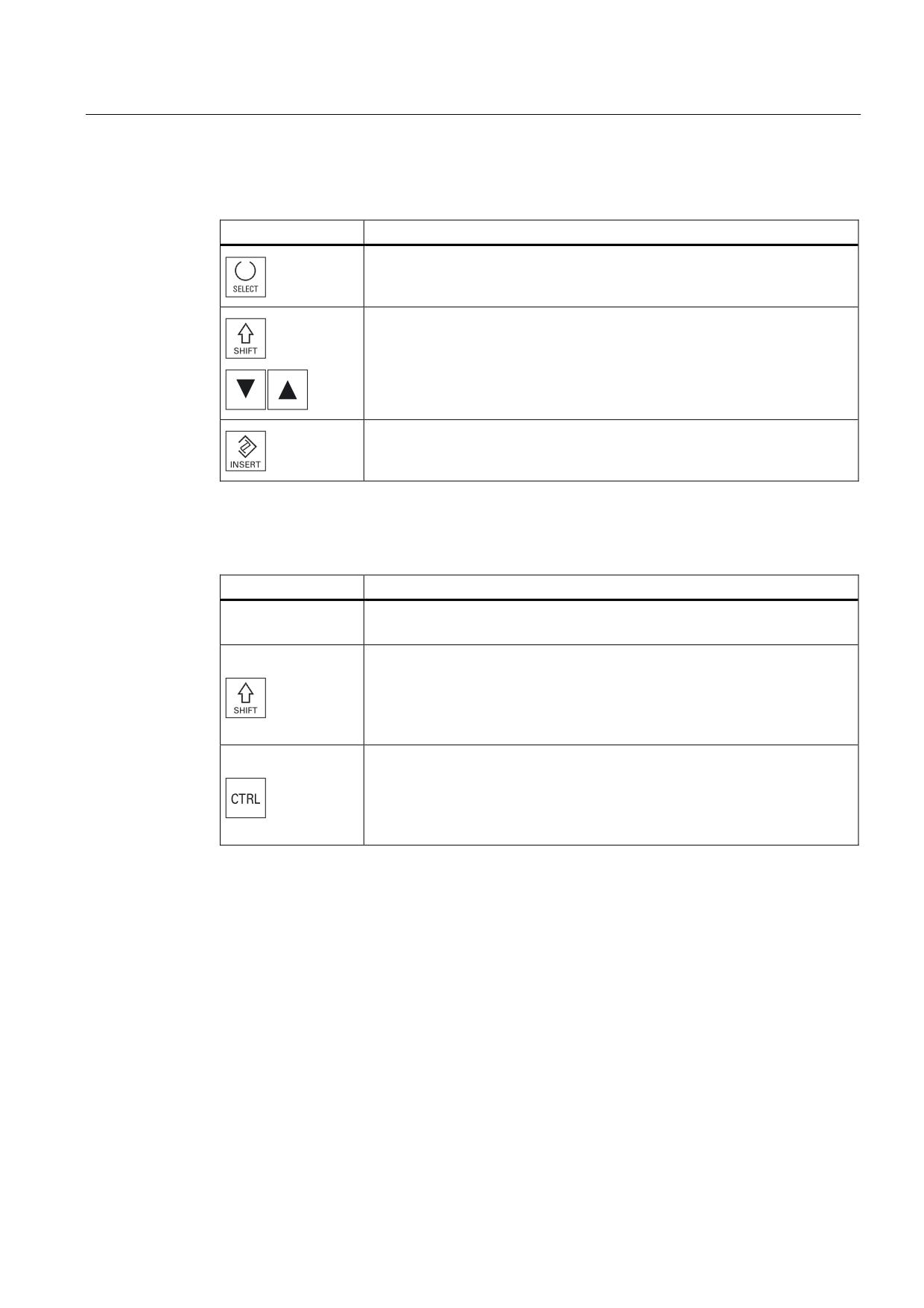
Selecting via keys
Key combination
Meaning
Renders or expands a selection.
You can only select individual elements.
Renders a consecutive selection.
A previously existing selection is canceled.
Selecting with the mouse
Key combination
Meaning
Left mouse
Click on element: The element is selected.
A previously existing selection is canceled.
Left mouse +
Expand selection consecutively up to the next click.
Pressed
Left mouse +
Expand selection to individual elements by clicking.
An existing selection will expand to include the element you clicked.
Pressed
Universal
Operating Manual, 03/2013, 6FC5398-6AP40-3BA1
245
Managing programs
9.9 Copying and pasting a directory/program
9.9
Copying and pasting a directory/program
To create a new directory or program that is similar to an existing program, you can save
time by copying the old directory or program and only changing selected programs or
program blocks.
The capability of copying and pasting directories and programs can also be used to
exchange data with other systems via USB/network drives (e.g. USB FlashDrive).
Copied files or directories can be pasted in a different location.
Note
You can only paste directories on local drives and on USB or network drives.
Note
Write protection
If the current directory is write-protected for the user, then the function is not offered.
Note
When you copy directories, any missing endings are added automatically.
All letters (except accented characters), numbers, and underscores are permitted for name
assignment. The names are automatically converted to upper-case letters, and extra dots
are converted to underscores.
Example
If the name is not changed during the copy procedure, a copy is created automatically:
MYPROGRAM.MPF is copied to MYPROGRAM__1.MPF. The next time it is copied, it is
changed to MYPROGRAM__2.MPF, etc.
If the files MYPROGRAM.MPF, MYPROGRAM__1.MPF, and MYPROGRAM__3.MPF
already exist in a directory, MYPROGRAM__2.MPF is created as the next copy of
MYPROGRAM.MPF.
Universal
246
Operating Manual, 03/2013, 6FC5398-6AP40-3BA1
Managing programs
9.9 Copying and pasting a directory/program
Procedure
1.
Select the "Program manager" operating area.
2.
Choose the desired storage location and position the cursor on the file
or directory which you would like to copy.
3.
Press the "Copy" softkey.
4.
Select the directory in which you want to paste your copied
directory/program.
5.
Press the "Paste" softkey.
If a directory/program of the same name already exists in this directory,
you are are informed. You are requested to assign a new name,
otherwise the directory/program is assigned a name by the system.
If the name contains illegal characters or is too long, a prompt will
appear for you to enter a permissible name.
6.
Press the "OK" or "Overwrite all" softkey if you want to overwrite
existing directories/programs.
- OR -
Press the "No overwriting" softkey if you do not want to overwrite
already existing directories/programs.
- OR -
Press the "Skip" softkey if the copy operation is to be continued with the
next file.
- OR -
Enter another name if you want to paste the directory/program under
another name and press the "OK" softkey.
Note
Copying files in the same directory
You cannot copy files to the same directory. You must copy the file under a new name.
Universal
Operating Manual, 03/2013, 6FC5398-6AP40-3BA1
247
Managing programs
9.10 Deleting a directory/program
9.10
Deleting a directory/program
Delete programs or directories from time to time that you are no longer using to maintain a
clearer overview of your data management. Back up the data beforehand, if necessary, on
an external data medium (e.g. USB FlashDrive) or on a network drive.
Please note that when you delete a directory, all programs, tool data and zero point data and
subdirectories that this directory contains are deleted.
Procedure
1.
Select the "Program manager" operating area.
2.
Choose the desired storage location and position the cursor on the file
or directory that you would like to delete.
3.
Press the ">>" and "Delete" softkeys.
A prompt appears as to whether you really want to delete the file or
directory.
4.
Press the "OK" softkey to delete the program/directory.
- OR -.
Press the "Cancel" softkey to cancel the process.
Universal
248
Operating Manual, 03/2013, 6FC5398-6AP40-3BA1
Managing programs
9.11 Changing file and directory properties
9.11
Changing file and directory properties
Information on directories and files can be displayed in the "Properties for ..." window.
Information on the creation date is displayed near the file's path and name.
You can change names.
Changing access rights
Access rights for execution, writing, listing and reading are displayed in the "Properties"
window.
● Execute: Is used for the selection for execution
● Write: Controls the changing and deletion of a file or a directory
For NC files, you have the option to set the access rights from keyswitch 0 to the current
access level, to be set separately for each file.
If an access level is higher than the current access level, it cannot be changed.
For external files (e.g. on a local drive), the access rights are displayed to you only if settings
have been executed for these files by the machine manufacturer. They cannot be changed
via the "Properties" window.
Settings for the access rights to directories and files
Via a configuration file and MD 51050, access rights of the directories and file types of the
NC and user memory (local drive) can be changed and pre-assigned.
References
A detailed description of the configuration can be found in the following documentation:
Commissioning Manual SINUMERIK Operate (IM9) / SINUMERIK 840D sl
Procedure
1.
Select the program manager.
2.
Choose the desired storage location and position the cursor on the file
or directory whose properties you want to display or change.
Universal
Operating Manual, 03/2013, 6FC5398-6AP40-3BA1
249
Managing programs
9.12 Set up drives
3.
Press the ">>" and "Properties" softkeys.
The "Properties from ..." window appears.
4.
Enter any necessary changes.
Note: You can save changes via the user interface in the NC memory.
5.
Press the "OK" softkey to save the changes.
9.12
Set up drives
9.12.1
Overview
Up to eight connections to so-called logical drives (data carriers) can be configured. These
drives can be accessed in the "Program manager" and "Startup" operating areas.
The following logical drives can be set up:
● USB interface
● CompactFlash card of the NCU, only for SINUMERIK Operate in the NCU
● Network drives
● Local hard disk of the PCU, only for SINUMERIK Operate on the PCU
Software option
In order to use the CompactFlash card as data carrier, you require the "Additional
HMI user memory on CF card of the NCU" option (not for SINUMERIK Operate on
PCU or PC).
Note
The USB interfaces of the NCU are not available for SINUMERIK Operate and therefore
cannot be configured.
Universal
250
Operating Manual, 03/2013, 6FC5398-6AP40-3BA1

Managing programs
9.12 Set up drives
9.12.2
Setting up drives
The "Set Up Drives" window is available in the "Start-up" operating area for configuration.
File
The created configuration data is stored in the "logdrive.ini" file. This file is located in the
/user/sinumerik/hmi/cfg directory.
General information
Entry
Meaning
Type
No drive
No drive defined.
USB local
Access to the USB memory medium is only realized via
the TCU to which it is connected.
USB drives are automatically identified if the memory
medium is inserted when SINUMERIK Operate powers-
up.
USB global
All of the TCUs in the plant network can access the USB
memory medium.
- USB global is not possible under Windows!
NW Windows/Linux
Network drive
Local drive
Local drive
Hard disk or user memory on the CompactFlash card.
FTP
Access to an external FTP server.
Connection
Front
USB interface that is located at the front of the operator
panel.
X203/X204
USB interface X203/X204 that is located at the rear of the
operator panel.
X204
For SIMATIC Thin Client the USB interface is X204.
Device
Names of the TCU to which the USB storage medium is
connected, e.g. tcu1. The NCU must already know the
TCU name.
Partition
Partition number on the USB memory medium, e.g. 1.
If a USB hub is used, specify the USB port of the hub.
Port
Interface for the FTP connection. The default port is 21.
Disconnect
After a disconnect timeout, the FTP connection is
disconnected. The timeout can be between 1 and 150 s.
10 s is the default setting.
Path
• Start direct directory of the data carrier that is
connected via the local drive.
• Network path to a directory that has been released in
the network. This path must always start with "//", e.g.
//Server01/share3.
Universal
Operating Manual, 03/2013, 6FC5398-6AP40-3BA1
251
Managing programs
9.12 Set up drives
Entry
Meaning
Access level
Assign access rights to the connections: From access
level 7 (keyswitch position 0) to access level 1
(manufacturer).
The particular assigned access level applies to all
operating areas.
Softkey text
2 lines are available as labeling text for the softkey. %n is
accepted as a line separator.
If the first line is too long, then it is automatically
separated into several lines.
If a blank is present, then this is used as line separator.
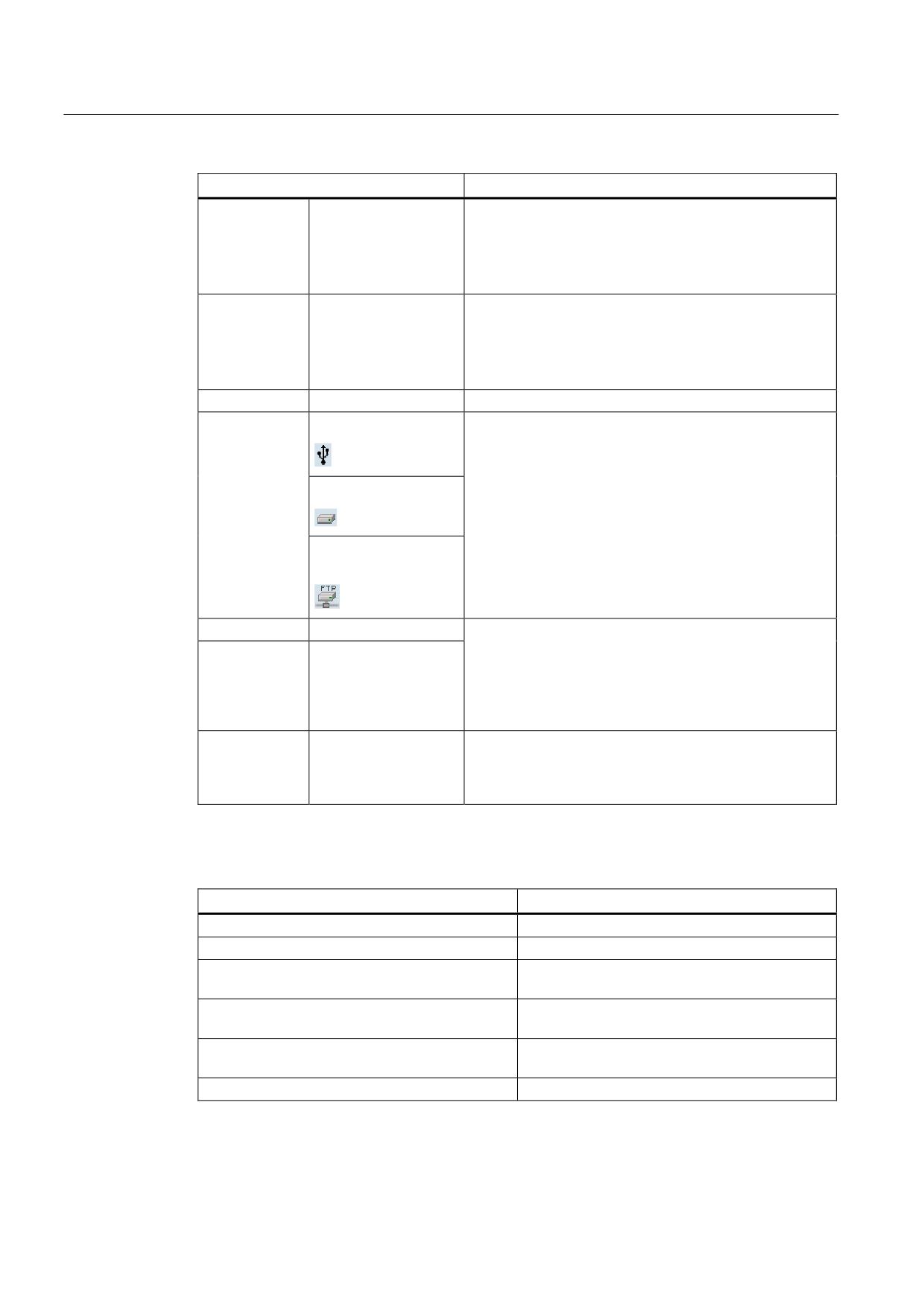
Softkey icon
No icon
No icon is displayed on the softkey.
sk_usb_front.png
The icon file name displayed on the softkey.
sk_local_drive.png
sk_network_drive_ftp.p
ng
Text file
slpmdialog
File for softkey dependent on the language. If nothing is
specified in the input fields, the text appears on the
Text context
SlPmDialog
softkey as was specified in the input field "Softkey text".
If your own text files are saved, then the text ID, which is
used to search for the text file, is specified in the "Softkey
text" input field.
User name
Enter the user name and the corresponding password for
which the directory is enabled on the server. The
Password
password is displayed in encoded form as string of "*"
characters and is stored in the "logdrive.ini" file.
Error messages
Error message
Meaning
Error occurred when closing a connection.
An existing drive was not able to be deactivated.
Error occurred when establishing a connection.
Drive connection was not able to be established.
Error occurred while establishing a connection:
Drive connection was not able to be established.
Incorrect entry or no authorization.
Incorrect data
The entered data is either incorrect or
inconsistent.
Function not available
The function is not supported with the current
software release.
Unknown error - error code:%1
Error was not able to be assigned.
Universal
252
Operating Manual, 03/2013, 6FC5398-6AP40-3BA1
Managing programs
9.12 Set up drives
Procedure
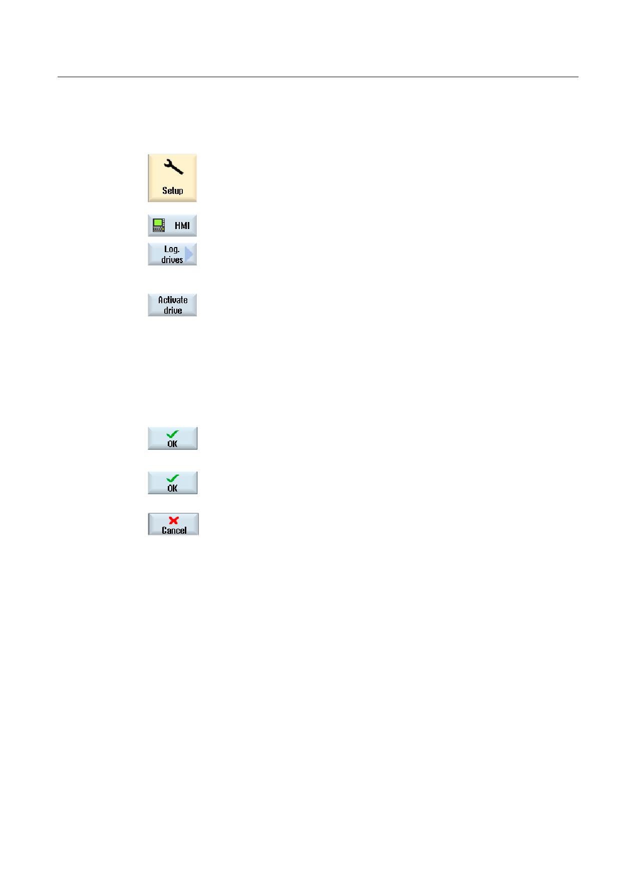
1.
Select the "Start-up" operating area.
2.
Press the "HMI" and "Log. drive" softkeys.
The "Set Up Drives" window opens.
3.
Select the data for the corresponding drive or enter the necessary data.
4.
Press the "Activate drive" softkey.
The drive is activated.
The operating system now checks the entered data and whether the
connection is established. An OK message is output in the dialog line if
an error is not identified.
The drive can be accessed.
- OR -
If the operating system identifies an error, then you receive an error
message.
Press the "OK" softkey.
You then return to the "Set Up Drives" window. Check and correct your
entries and re-activate the drive.
If you press the "OK" softkey, the modified data is accepted without any
feedback message. You do not receive any message about a successful
or unsuccessful connection.
If you press the "Cancel" softkey, then all of the data that has not been
activated is rejected.
Universal
Operating Manual, 03/2013, 6FC5398-6AP40-3BA1
253
Managing programs
9.13 Viewing PDF documents
9.13
Viewing PDF documents
You have the option of displaying HTML documents, as well as PDFs, on all drives of the
program manager via the data tree of the system data.
Note
A preview of the documents is only possible for PDFs.
Procedure
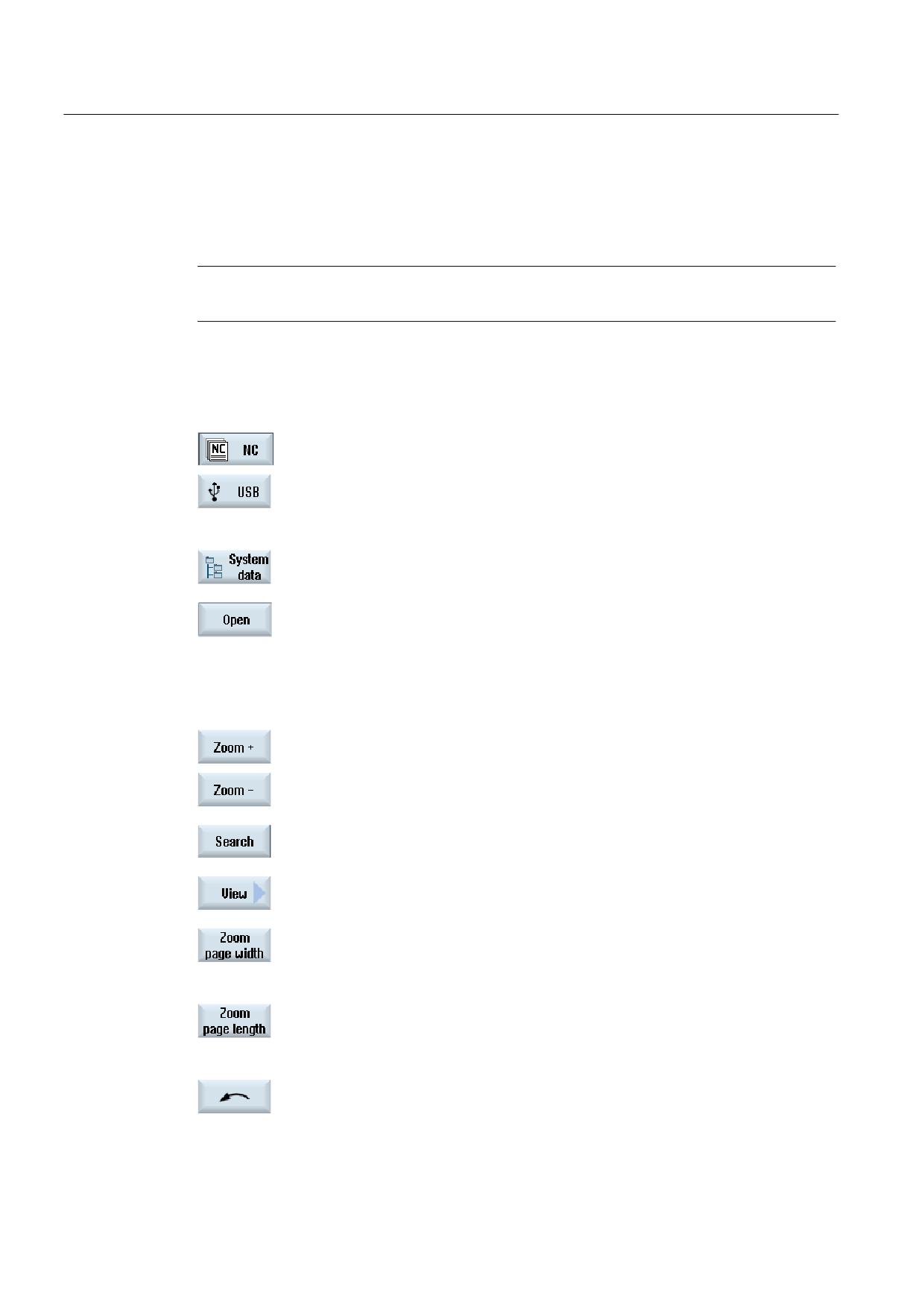
1.
In the "Program manager" operating area, select the desired storage
medium.
- OR -
Select the desired storage location in the "Commissioning" operating
area in the data tree of the "System data".
2.
Position the cursor on the PDF or the HTML file that you want to
display, and press the "Open" softkey.
The selected file is displayed on the screen.
The storage path of the document is displayed in the status bar. The
current page as well as the total number of pages of the document are
displayed.
3.
Press the "Zoom +" or "Zoom -" softkey to enlarge of reduce the size of
the display.
4.
Press the "Search" softkey if you want to search for specific texts in the
PDF.
5.
Press the "View" softkey to change the representation of the PDF.
A new vertical softkey bar appears.
6.
Press the "Zoom page width" softkey to display the document in full
width on the screen.
- OR -
Press the "Zoom page height" softkey to display the document with full
height on the screen.
- OR -
Press the "Rotate left" softkey to rotate the document through 90
degrees to the left.
- OR -
Universal
254
Operating Manual, 03/2013, 6FC5398-6AP40-3BA1

Managing programs
9.14 EXTCALL
Press the "Rotate right" softkey to rotate the document through 90
degrees to the right.
7.
Press the "Back" softkey to return to the previous window.
8.
Press the "Close" softkey to exit the PDF display.
9.14
EXTCALL
The EXTCALL command can be used to access files on a local drive, USB data carriers or
network drives from a part program.
The programmer can set the source directory with the setting data SD $SC42700
EXT_PROG_PATH and then specify the file name of the subprogram to be loaded with the
EXTCALL command.
Supplementary conditions
The following supplementary conditions must be taken into account with EXTCALL calls:
● You can only call files with the MPF or SPF extension via EXTCALL from a network drive.
● The files and paths must comply with the NCK naming conventions (max. 25 characters
for the name, 3 characters for the identifier).
● A program is found on a network drive with the EXTCALL command if
- with SD $SC42700 EXT_PROG_PATH the search path refers to the network drive or
a directory contained on the network drive. The program must be stored directly on
that level, no subdirectories are searched.
- without SD $SC42700 the correct location of the program is specified in the EXTCALL
call itself by means of a fully qualified path that can also point to a subdirectory of the
network drive.
● For programs that were generated on external storage media (Windows system) observe
upper- and lower-case syntax.
Note
Maximum path length for EXTCALL
The path length must not exceed 112 characters. The path comprises the contents of the
setting data (SD $SC42700) and the path data for EXTCALL call from the part program.
Universal
Operating Manual, 03/2013, 6FC5398-6AP40-3BA1
255
Managing programs
9.14 EXTCALL
Examples of EXTCALL calls
The setting data can be used to perform a targeted search for the program.
●
Call of USB drive on TCU (USB storage device on interface X203), if SD42700 is empty:
e.g. EXTCALL "//TCU/TCU1 /X203 ,1/TEST.SPF"
- OR -
Call of USB drive on TCU (USB storage device on interface X203), if SD42700
"//TCU/TCU1 /X203 ,1" contains: EXTCALL "TEST.SPF"
●
Call of the USB front connection (USB-FlashDrive), if SD $SC 42700 is empty: e.g.
EXTCALL "//ACTTCU/FRONT,1/TEST.SPF"
- OR -
Call of USB front connection (USB-FlashDrive), if SD42700 "//ACTTCU/FRONT,1"
contains: EXTCALL "TEST.SPF"
●
Call of network drive, if SD42700 is empty: e.g. EXTCALL "//computer name/enabled
drive/TEST.SPF"
- OR -
Call of the network drive, if SD $SC42700 "//Computer name/enabled drive" contains:
EXTCALL "TEST.SPF"
●
Use of the HMI user memory (local drive):
- On the local drive, you have created the directories part programs (mpf.dir),
subprograms (spf.dir) and workpieces (wks.dir) with the respective workpiece
directories (.wpd):
SD42700 is empty: EXTCALL "TEST.SPF"
The same search sequence is used on the CompactFlash card as in the NCK part
program memory.
- On the local drive, you have created your own directory (e.g. my.dir):
Specification of the complete path: e.g. EXTCALL
"/card/user/sinumerik/data/prog/my.dir/TEST.SPF"
A search is performed for the specified file.
Note
Abbreviations for local drive, CompactFlash card and USB front connection
As abbreviation for the local drive, the CompactFlash card and the USB front
connection you can use the abbreviation LOCAL_DRIVE:, CF_CARD: and USB: (e.g.
EXTCALL "LOCAL_DRIVE:/spf.dir/TEST.SPF").
Alternatively, you can also use the abbreviations CF_Card and LOCAL_DRIVE.
Universal
256
Operating Manual, 03/2013, 6FC5398-6AP40-3BA1
Managing programs
9.14 EXTCALL
Software options
To display the "Local drive" softkey, you require the "Additional HMI user
memory on CF card of the NCU" option (not for SINUMERIK Operate on
PCU50 / PC).
NOTICE
Possible interruption when executing from USB FlashDrive
Direct execution from a USB-FlashDrive is not recommended.
There is no protection against contact problems, falling out, breakage through knocking or
unintentional removal of the USB-FlashDrive during operation.
Disconnecting it during operation will result in immediate stopping of the machining and,
thus, to the workpiece being damaged.
Machine manufacturer
Processing EXTCALL calls can be enabled and disabled.
Please refer to the machine manufacturer's specifications.
Universal
Operating Manual, 03/2013, 6FC5398-6AP40-3BA1
257
Managing programs
9.15 Backing up data
9.15
Backing up data
9.15.1
Generating an archive in the Program Manager
You have the option of archiving individual files from the NC memory and the local drive.
Archive formats
You have the option of saving your archive in the binary and punched tape format.
Save target
The archive folder of the system data in the "Startup" operating area as well as USB and
network drives are available as save target.
Procedure
1.
Select the "Program Manager" operating area.
2.
Select the storage location for the file/files to be archived.
3.
In the directories, select the required file from which you want to create
an archive.
- OR -
If you want to back up several files or directories, press the "Select"
softkey and, using the cursor keys or the mouse, select the required
directories or files.
4.
Press the ">>" and "Archive" softkeys.
5.
Press the "Generate archive" softkey.
The "Generate Archive: Select archiving" window opens.
6.
Position the cursor to the required storage location, press the "Search"
softkey, enter the required search term in the search dialog and press
the "OK" softkey if you wish to search for a specific directory or
subdirectory.
Note: The place holders "*" (replaces any character string) and "?"
(replaces any character) make it easier for you to perform a search.
- OR -
Universal
258
Operating Manual, 03/2013, 6FC5398-6AP40-3BA1
Managing programs
9.15 Backing up data
Select the required storage location, press the "New directory" softkey,
enter the required name in the "New directory" window and press the
"OK" softkey to create a directory.
7.
Press "OK".
The "Generate Archive: Name" window opens.
9.
Select the format (e.g. archive ARC (binary format)), enter the desired
name and press the "OK" softkey.
A message informs you if archiving was successful.
9.15.2
Generating an archive via the system data
If you only want to backup specific data, then you can select the desired files directly from
the data tree and generate an archive.
Archive formats
You have the option of saving your archive in the binary and punched tape format.
You can display the contents of the selected files (XML, ini, hsp, syf files, programs) in a
preview.
You can display information about the file, such as path, name, date of creation and change,
in a Properties window.
Precondition
The access rights depend on the relevant areas and range from protection level 7 (key
switch position 0) to protection level 2 (password: Service).
Storage locations
● CompactFlash card under
/user/sinumerik/data/archive, or
/oem/sinumerik/data/archive
● All configured logical drives (USB, network drives)
Software option
In order to save archives on the CompactFlash card in the user area you
require the option "Additional HMI user memory on CF card of NCU".
Universal
Operating Manual, 03/2013, 6FC5398-6AP40-3BA1
259
Managing programs
9.15 Backing up data
NOTICE
Possible data loss when using USB flash drives
USB-FlashDrives are not suitable as persistent memory media.
Procedure
1.
Select the "Startup" operating area.
2.
Press the "System data" softkey.
The data tree opens.
3.
In the data tree, select the required files from which you want to
generate an archive.
- OR -
If you want to back up several files or directories, press the "Select"
softkey and, using the cursor keys or the mouse, select the required
directories or files.
4.
If you press the ">>" softkey, further softkeys are displayed on the
vertical bar.
5.
Press the "Preview window" softkey.
The contents of the selected file are displayed in a small window. Press
the "Preview window" softkey again to close the window.
6.
Press the "Properties" softkey.
Information about the selected file is displayed in a small window. Press
the "OK" softkey to close the window.
7.
Press the "Search" softkey.
Enter the required search term in the search dialog and press the "OK"
softkey if you wish to search for a specific directory or subdirectory.
Note: The place holders "*" (replaces any character string) and "?"
(replaces any character) make it easier for you to perform a search.
8.
Press the "Archive" and "Generate archive" softkeys.
The "Generate Archive: Select Storage Location" window opens.
The "Archive" folder with the subfolders "User" and "Manufacturer" as
well as the storage media (e.g. USB) are displayed.
Universal
260
Operating Manual, 03/2013, 6FC5398-6AP40-3BA1
Managing programs
9.15 Backing up data
9.
Select the required location for archiving and press the "New directory"
softkey to create a suitable subdirectory.
The "New Directory" window opens.
10.
Enter the required name and press the "OK" softkey.
The directory is created below the selected folder.
11.
Press the "OK" softkey.
The "Generate Archive: Name" window opens.
12.
Select the format (e.g. archive ARC (binary format)), enter the desired
name and press the "OK" softkey to archive the file/files.
A message informs you if archiving was successful.
13.
Press the "OK" softkey to confirm the message and end the archiving
operation.
An archive file in .arc format is created in the selected directory.
9.15.3
Reading in an archive in the Program Manager
In the "Program Manager" operating area, you have the option of reading in archives from
the archive folder of the system data as well as from configured USB and network drives.
Software option
In order to read-in user archives in the "Program Manager" operating area,
you require the option "Additional HMI memory on CF Card of NCU" (not for
SINUMERIK Operate on PCU50 / PC).
Procedure
1.
Select the "Program Manager" operating area.
2.
Press the "Archive" and "Read in archive" softkeys.
The "Read in archive: Select archive" window opens.
Universal
Operating Manual, 03/2013, 6FC5398-6AP40-3BA1
261
Managing programs
9.15 Backing up data
3.
Select the archive storage location and position the cursor on the
required archive.
Note: When the option is not set, the folder for user archives is
only displayed if the folder contains at least one archive.
- OR -
Press the "Search" softkey and in the search dialog, enter the
name of the archive file with file extension (*.arc) if you wish to
search for a specific archive and press the "OK" softkey.
4.
Press the "OK" or "Overwrite all" softkey to overwrite existing files.
- OR -
Press the "Do not overwrite" softkey if you do not want to
overwrite already existing files.
- OR -
Press the "Skip" softkey if the read-in operation is to be continued
with the next file.
The "Read In Archive" window opens and a progress message
box appears for the read-in process.
You will then obtain a "Read error log for archive" in which the
skipped or overwritten files are listed.
5.
Press the "Cancel" softkey to cancel the read-in process.
See also
Searching directories and files (Page 242)
Universal
262
Operating Manual, 03/2013, 6FC5398-6AP40-3BA1
Managing programs
9.15 Backing up data
9.15.4
Read in archive from system data
If you want to read in a specific archive, you can select this directly from the data tree.
Procedure
1.
Select the "Start-up" operating area.
2.
Press the "System data" softkey.
3.
In the data tree below the "Archive" directory, in the "User" folder,
select the file that you wish to read in.
4.
Press the "Read in" softkey.
5.
Press the "OK" or "Overwrite all" softkey to overwrite existing files.
- OR -
Press the "Do not overwrite" softkey if you do not want to
overwrite already existing files.
- OR -
Press the "Skip" softkey if the read-in operation is to be continued
with the next file.
The "Read In Archive" window opens and a progress message
box appears for the read-in process.
You will then obtain a "Read error log for archive" in which the
skipped or overwritten files are listed.
6.
Press the "Cancel" softkey to cancel the read-in process.
Universal
Operating Manual, 03/2013, 6FC5398-6AP40-3BA1
263

Managing programs
9.16 Setup data
9.16
Setup data
Apart from programs, you can also save tool data and zero point settings.
You can use this option, for example, to backup the required tools and zero point data for a
specific G code program. If you want to execute this program at a later point in time, you will
then have quick access to the relevant settings.
Even tool data that you have measured on an external tool setting station can be copied
easily into the tool management system using this option.
Note
Backing up setup data from part programs
Setup data from part programs can only be backed up if they have been saved in the
"Workpieces" directory.
For part programs, which are located in the "Part programs" directory, "Save setup data" is
not listed.
Backing up data
Data
Tool data
• No
• Complete tool list
Magazine assignment
• Yes
• No
Zero points
• No
The selection box "Basis zero point" is hidden
• All
Basic zero points
• No
• Yes
Directory
The directory is displayed, in which the selected program is located.
File name
Here you have the option of changing the suggested file names.
Note
Magazine assignment
You can only read out the magazine assignments if your system provides support for loading
and unloading tool data to and from the magazine.
Universal
264
Operating Manual, 03/2013, 6FC5398-6AP40-3BA1
Managing programs
9.16 Setup data
Procedure
1.
Select the "Program Manager" operating area.
2.
Position the cursor on the program whose tool and zero point
data you wish to back up.
3.
Press the ">>" and "Archive" softkeys.
4.
Press the "Setup data" softkey.
The "Backup setup data" window opens.
5.
Select the data you want to back up.
6.
When required, change the specified name of the originally
selected program here in the "File name" field.
7.
Press the "OK" softkey.
The setup data will be set up in the same directory in which the
selected program is stored.
The file is automatically saved as INI file.
Note
Program selection
If a main program as well as an INI file with the same name are in a directory, when
selecting the main program, initially, the INI file is automatically started. In this way,
unwanted tool data can be changed.
Machine manufacturer
Please refer to the machine manufacturer's specifications.
Universal
Operating Manual, 03/2013, 6FC5398-6AP40-3BA1
265
Managing programs
9.16 Setup data
9.16.1
Reading-in set-up data
When reading-in, you can select which of the backed-up data you wish to read-in:
● Tool data
● Magazine assignment
● Zero points
● Basic zero point
Tool data
Depending on which data you have selected, the system behaves as follows:
● Complete tool list
First, all tool management data are deleted and then the saved data are imported.
● All tool data used in the program
If at least one of the tools to be read in already exists in the tool management system,
you can choose between the following options.
Select the "Replace all" softkey to import all tool data. Any existing tools
will now be overwritten without a warning prompt.
- OR -
Press the "Do not overwrite" softkey if existing tools must not be
overwritten.
Already existing tools are skipped, without you receiving any queries.
- OR -
Press the "Skip" softkey if already existing tools are not to be
overwritten.
For an already existing tool, you receive a query.
Selecting loading point
For a magazine, if more than one loading point was set-up, using the "Select loading point"
softkey, you have the option of opening a window in which you can assign a loading point to
a magazine.
Universal
266
Operating Manual, 03/2013, 6FC5398-6AP40-3BA1
Managing programs
9.16 Setup data
Procedure
1.
Select the "Program Manager" operating area.
2.
Position the cursor on the file with the backed-up tool and zero point
data (*.INI) that you wish to re-import.
3.
Press the <Cursor right> key
- OR -
Double-click the file.
The "Read-in setup data" window opens.
4.
Select the data (e.g. magazine assignment) that you wish to read-in.
5.
Press the "OK" softkey.
Universal
Operating Manual, 03/2013, 6FC5398-6AP40-3BA1
267
Managing programs
9.17 RS-232-C
9.17
RS-232-C
9.17.1
Reading-in and reading-out archives
Availability of the RS-232-C serial interface
You have the option of reading-out and reading-in archives in the "Program manager"
operating area as well as in the "Start-up" operating area via the RS-232-C serial interface.
● SINUMERIK Operate on the NCU:
The softkeys for the RS-232-C are available as soon as an option module is connected
and the slot is occupied.
● SINUMERIK Operate on the PCU:
The softkeys for the RS-232-C are always available.
Reading-out archives
The files to be sent (directories or individual files) are zipped in an archive (*.ARC). If you
send an archive (*.arc), this is sent directly without being additionally zipped. If you have
selected an archive (*.arc) together with an additional file (e.g. directory), then these are
zipped into a new archive and are then sent.
Reading-in archives
Only archives can be read-in via the RS-232-C. These are transferred and then
subsequently unzipped.
Note
Start-up archive
If you read in a start-up archive via the RS-232-C, then this is immediately activated.
Universal
268
Operating Manual, 03/2013, 6FC5398-6AP40-3BA1
Managing programs
9.17 RS-232-C
Externally processing the punched tape format
If you wish to externally process an archive, then generate this in the punched tape format.
Using the SinuCom commissioning and service tool SinuCom ARC, you can process the
archive in the binary format and in the commissioning archive.
Procedure
1.
Select the "Program manager" operating area, and press the
"NC" or "Local drive" softkey.
- OR -
Select the "Start-up" operating area and press the "System data"
softkey.
Reading-out archives
2.
Select the directories or the files that you wish to send via RS-
232-C.
3.
Press the ">>" and "Archive" softkeys.
4.
Press the "RS-232-C send" softkey.
- OR -
Reading in an archive
Press the "RS-232-C receive" softkey if you wish to read-in files
via RS-232-C.
Universal
Operating Manual, 03/2013, 6FC5398-6AP40-3BA1
269
Managing programs
9.17 RS-232-C
V24 setting
Meaning
Protocol
The following protocols are supported for transfer via the V24 interface:
• RTS/CTS (default setting)
• Xon/Xoff
Transfer
It is also possible to use a secure protocol for data transfer (ZMODEM
protocol).
• Normal (default setting)
• secure
For the selected interface, secure data transfer is set in conjunction
with handshake RTS/CTS.
Baud rate
Transfer rate: Transfer rates of up to 115 kbaud can be selected. The
baud rate that can be used depends on the connected device, the
cable length and the general electrical conditions.
•
110
•
•
19200 (default)
• ...
•
115200
Archive format
• Punched tape format (default setting)
• Binary format (PC format)
V24 settings (details)
Interface
• COM1
Parity
Parity bits are used for error detection: The parity bits are added to the
coded characters to make the number of positions set to "1" an uneven
number (uneven parity) or to an even number (even parity).
• None (default setting)
• Odd
• Even
Stop bits
Number of stop bits for asynchronous data transfer.
•
1 (default)
•
2
Data bits
Number of data bits for asynchronous data transfer.
•
5 bits
• ...
•
-8 bits (default setting)
XON (hex)
Only for punched tape format
XOFF (hex)
Only for punched tape format
Universal
270
Operating Manual, 03/2013, 6FC5398-6AP40-3BA1
Managing programs
9.17 RS-232-C
V24 setting
Meaning
End of data transfer (hex)
Only for punched tape format
Stop with end of data transfer character
The default setting for the end of data transfer character is (HEX) 1A
Time monitoring (sec)
Time monitoring
For data transfer problems or at the end of data transfer (without end
of data transfer character) data transfer is interrupted after the
specified number of seconds.
The time monitoring is controlled by a time generator (clock) that is
started with the first character and is reset with each transferred
character.
The time monitoring can be set (seconds).
Procedure
1.
Select the "Program Manager" operating area.
2.
Press the "NC" or "Local drive" softkey.
3.
Press the ">>" and "Archive" softkeys.
4.
Select the "V24 settings" softkey.
The "Interface: V24" window is opened.
5.
The interface settings are displayed.
6.
Press the "Details" softkey if you wish to view and process
additional settings for the interface.
Universal
Operating Manual, 03/2013, 6FC5398-6AP40-3BA1
271
Managing programs
9.17 RS-232-C
Universal
272
Operating Manual, 03/2013, 6FC5398-6AP40-3BA1
Teaching in a program
10
10.1
Overview
The "Teach in" function can be used to edit programs in the "AUTO" and "MDA" modes. You
can create and modify simple traversing blocks.
You traverse the axes manually to specific positions in order to implement simple machining
sequences and make them reproducible. The positions you approach are applied.
In "AUTO" teach-in mode, the selected program is "taught".
In "MDA" teach-in mode, you teach to the MDA buffer.
External programs, which may have been rendered offline, can therefore be adjusted and
modified according to need.
10.2
General sequence
General sequence
Select the desired program block, press the relevant softkey "Teach
position", "Rap. tra. G01", "Straight line G1" or "Circ. interm. pos. CIP",
and "Circ. end pos. CIP" and traverse the axes to change the program
block.
You can only overwrite a block with a block of the same type.
- OR -
Position the cursor at the desired point in the program, press the
relevant softkey "Teach position", "Rap. tra. G01", "Straight line G1" or
"Circ. interp. pos. CIP", and "Circ. end pos. CIP" and traverse the axes
to insert a new program block.
In order for the block to be inserted, the cursor must be positioned in an
empty line using the cursor key and input key.
Press the "Accept" softkey to teach-in the modified or new program
block.
Universal
Operating Manual, 03/2013, 6FC5398-6AP40-3BA1
273
Teaching in a program
10.3 Inserting a block
Note
All defined axes are "taught in" in the first teach-in block. In all additional teach-in blocks,
only axes modified by axis traversing or manual input are "taught in".
If you exit teach-in mode, this sequence begins again.
Operating mode or operating area switchover
If you switch to another operating mode or operating area in teach-in mode, the position
changes will be canceled and teach-in mode will be cleared.
10.3
Inserting a block
You have the option of traversing the axes and writing the current actual values directly to a
new position block.
Requirement
"AUTO" mode: The program to be edited is selected.
Proceed as follows
1.
Select the "Machine" operating area.
2.
Press the <AUTO> or <MDA> key.
3.
Press the <TEACH IN> key.
4.
Press the "Teach prog." softkey.
Universal
274
Operating Manual, 03/2013, 6FC5398-6AP40-3BA1
Teaching in a program
10.3 Inserting a block
5.
Traverse the axes to the relevant position.
6.
Press the "Teach position" softkey.
A new program block with the current actual position values will be
created.
10.3.1
Input parameters for teach-in blocks
Parameters for teach-in of position and teach-in of G0, G1, and circle end position CIP
Parameter
Description
X
Approach position in X direction
Y
Approach position in Y direction
Z
Approach position in Z direction
F
Feedrate (mm/r; mm/min) - only for teach-in of G1 and circle end position CIP
Parameters for teach-in of circle intermediate position CIP
Parameter
Description
I
Coordinate of the circle center point in the X direction
J
Coordinate of the circle center point in the Y direction
K
Coordinate of the circle center point in the Z direction
Transition types for teach-in of position and teach-in of G0 and G1, and ASPLINE
The following parameters are offered for the transition:
Parameter
Description
G60
Exact stop
G64
Corner rounding
G641
Programmable corner rounding
G642
Axis-specific corner rounding
G643
Block-internal corner rounding
G644
Axis dynamics corner rounding
Universal
Operating Manual, 03/2013, 6FC5398-6AP40-3BA1
275
Teaching in a program
10.3 Inserting a block
Motion types for teach-in of position and teach-in of G0 and G1
The following motion parameters are offered:
Parameter
Description
CP
Path-synchronous
PTP
Point-to-point
PTPG0
Only G0 point-to-point
Transition behavior at the beginning and end of the spline curve
The following motion parameters are offered:
Parameter
Description
Start
BAUTO
Automatic calculation
BNAT
Curvature is zero or natural
BTAN
Tangential
End
EAUTO
Automatic calculation
ENAT
Curvature is zero or natural
ETAN
Tangential
Universal
276
Operating Manual, 03/2013, 6FC5398-6AP40-3BA1
Teaching in a program
10.4 Teach-in via Windows
10.4
Teach-in via Windows
10.4.1
General information
The cursor must be positioned on an empty line.
The windows for pasting program blocks contain input and output fields for the actual values
in the WCS. Depending on the default setting, selection fields with parameters for motion
behavior and motion transition are available.
When first selected, the input fields are empty unless axes were already traversed before the
window was selected.
All data from the input/output fields are transferred to the program via the "Accept" softkey.
Precondition
"AUTO" mode: The program to be edited is selected.
Procedure
1
Select the "Machine" operating area.
2.
Press the <AUTO> or <MDA> key.
3.
Press the <TEACH IN> key.
4.
Press the "Teach prog." softkey.
5.
Use the cursor and input keys to position the cursor at the desired point
in the program.
If an empty row is not available, insert one.
6.
Press the softkeys "Rap. tra. G0", "Straight line G1", or Circ. interm.
pos. CIP" and "Circ. end pos. CIP".
The relevant windows with the input fields are displayed.
7.
Traverse the axes to the relevant position.
Universal
Operating Manual, 03/2013, 6FC5398-6AP40-3BA1
277

Teaching in a program
10.4 Teach-in via Windows
8.
Press the "Accept" softkey.
A new program block will be inserted at the cursor position.
- OR -
Press the "Cancel" softkey to cancel your input.
10.4.2
Teach in rapid traverse G0
You traverse the axes and teach-in a rapid traverse block with the approached positions.
Note
Selection of axes and parameters for teach-in
You can select the axes to be included in the teach-in block in the "Settings" window.
You also specify here whether motion and transition parameters are offered for teach-in.
10.4.3
Teach in straight G1
You traverse the axes and teach-in a machining block (G1) with the approached positions.
Note
Selection of axes and parameters for teach-in
You can select the axes to be included in the teach-in block in the "Settings" window.
You also specify here whether motion and transition parameters are offered for teach-in.
10.4.4
Teaching in circle intermediate and circle end point CIP
Enter the intermediate and end positions for the circle interpolation CIP. You teach-in each of
these separately in a separate block. The order in which you program these two points is not
specified.
Note
Make sure that the cursor position does not change during teach-in of the two positions.
You teach-in the intermediate position in the "Circle intermediate position CIP" window.
You teach-in the end position in the "Circle end position CIP" window.
Universal
278
Operating Manual, 03/2013, 6FC5398-6AP40-3BA1
Teaching in a program
10.4 Teach-in via Windows
The intermediate or interpolation point is only taught-in with geometry axes. For this reason,
at least 2 geometry axes must be set up for the transfer.
Note
Selection of axes for teach in
You can select the axes to be included in the teach-in block in the "Settings" window.
10.4.5
Teach-in A spline
For Akima-spline interpolation, you enter interpolation points that are connected by a smooth
curve.
Enter a starting point and specify a transition at the beginning and end.
You teach-in each interpolation point via "Teach in of position".
Software option
You require the "Spline-Interpolation" option for A Spline interpolation.
Note
The relevant option bit must be set to enable you to program a spline interpolation.
Machine manufacturer
Please refer to the machine manufacturer's specifications.
Procedure
1.
Select the "Machine" operating area.
2.
Press the <AUTO> or <MDA> key.
Universal
Operating Manual, 03/2013, 6FC5398-6AP40-3BA1
279
Teaching in a program
10.4 Teach-in via Windows
3.
Press the <TEACH IN> key.
4.
Press the "Teach prog." softkey.
5.
Press the ">>" and "ASPLINE" softkeys.
The "Akima-spline" window opens with the input fields.
6.
Traverse the axes to the required position and if necessary, set the
transition type for the starting point and end point.
7.
Press the "Accept" softkey.
A new program block will be inserted at the cursor position.
- OR -
Press the "Cancel" softkey to cancel your input.
Note
Selection of axes and parameters for teach-in
You can select the axes to be included in the teach-in block in the "Settings" window.
You also specify here whether motion and transition parameters are offered for teach-in.
Universal
280
Operating Manual, 03/2013, 6FC5398-6AP40-3BA1
Teaching in a program
10.5 Editing a block
10.5
Editing a block
You can only overwrite a program block with a teach-in block of the same type.
The axis values displayed in the relevant window are actual values, not the values to be
overwritten in the block.
Note
If you wish to change any variable in a block in the program block window other than the
position and its parameters, then we recommend alphanumerical input.
Requirement
The program to be processed is selected.
Procedure
1.
Select the "Machine" operating area.
2.
Press the <AUTO> or <MDA> key.
3.
Press the <TEACH IN> key.
4.
Press the "Teach prog." softkey.
5.
Click the program block to be edited.
6.
Press the relevant softkey "Teach position, "Rap. tra. G0", "Straight line
G1", or "Circ. interm. pos. CIP", and "Circ. end pos. CIP".
The relevant windows with the input fields are displayed.
7.
Traverse the axes to the desired position and press the "Accept"
softkey.
The program block is taught with the modified values.
- OR -
Press the "Cancel" softkey to cancel the changes.
Universal
Operating Manual, 03/2013, 6FC5398-6AP40-3BA1
281
Teaching in a program
10.6 Selecting a block
10.6
Selecting a block
You have the option of setting the interrupt pointer to the current cursor position. The next
time the program is started, processing will resume from this point.
With teach-in, you can also change program areas that have already been executed. This
automatically disables program processing.
You must press reset or select a block to resume the program.
Requirement
The program to be processed is selected.
Proceed as follows
1.
Select the "Machine" operating area.
2.
Press the <AUTO> key.
3.
Press the <TEACH IN> key.
4.
Press the "Teach prog." softkey.
5.
Place the cursor on the desired program block.
6.
Press the "Block selection" softkey.
Universal
282
Operating Manual, 03/2013, 6FC5398-6AP40-3BA1
Teaching in a program
10.7 Deleting a block
10.7
Deleting a block
You have the option of deleting a program block entirely.
Requirement
"AUTO" mode: The program to be processed is selected.
Procedure
1.
Select the "Machine" operating area.
2.
Press the <AUTO> or <MDA> key.
3.
Press the <TEACH IN> key.
4.
Press the "Teach prog." softkey.
5.
Click the program block to be deleted.
6.
Press the ">>" and "Delete block" softkeys.
The program block on which the cursor is positioned is deleted.
Universal
Operating Manual, 03/2013, 6FC5398-6AP40-3BA1
283
Teaching in a program
10.8 Settings for teach-in
10.8
Settings for teach-in
In the "Settings" window, you define which axes are to be included in the teach-in block and
whether motion-type and continuous-path mode parameters are to be provided.
Proceed as follows
1.
Select the "Machine" operating area.
2.
Press the <AUTO> or <MDA> key.
3.
Press the <TEACH IN> key.
4.
Press the "Teach prog." softkey.
5.
Press the ">>" and "Settings" softkeys.
The "Settings" window appears.
6.
Under "Axes to be taught" and "Parameters to be taught", select the
check boxes for the relevant settings and press the "Accept" softkey to
confirm the settings.
Universal
284
Operating Manual, 03/2013, 6FC5398-6AP40-3BA1
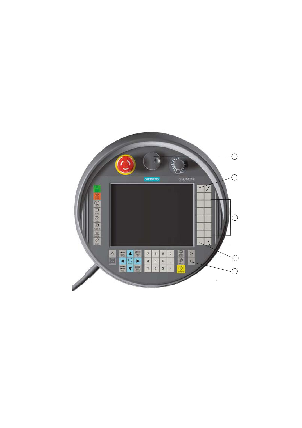
HT 8
11
11.1
HT 8 overview
The mobile SINUMERIK HT 8 handheld terminal combines the functions of an operator
panel and a machine control panel. It is therefore suitable for visualization, operation, teach
in, and programming at the machine.
1
Customer keys (user-defined)
2
Traversing keys
3
User menu key
4
Handwheel (optional)
Operation
The 7.5 TFT color display provides touch operation.
Universal
Operating Manual, 03/2013, 6FC5398-6AP40-3BA1
285

HT 8
11.1 HT 8 overview
It also has membrane keys for traversing the axes, for numeric input, for cursor control, and
for machine control panel functions like start and stop.
It is equipped with an emergency stop button and two 3-position enabling buttons. You can
also connect an external keyboard.
References
For more information about connection and startup of the HT 8, see the following references:
Commissioning Manual SINUMERIK Operate (IM9) / SINUMERIK 840D sl
Customer keys
The four customer keys are freely assignable and can be set up customer-specifically by the
machine manufacturer.
Machine manufacturer
Please refer to the machine manufacturer's specifications.
Integrated machine control panel
The HT 8 has an integrated machine control panel consisting of keys (e.g. start, stop,
traversing keys, etc.), and keys reproduced as softkeys (see machine control panel menu).
See Section "Controls on the machine control panel" for a description of the individual keys.
Note
PLC interface signals that are triggered via the softkeys of the machine control panel menus
are edge triggered.
Enabling button
The HT 8 has two enabling buttons. Thus, you can initiate enabling functions for operations
that require enabling (e.g. displaying and operating of traversing keys) with either your right
hand or your left hand.
Enabling buttons are available for the following key positions:
● Released (no activation)
● Enabling (center position) - enabling for channel 1 and 2 is on the same switch
● Panic (completely pushed through)
Universal
286
Operating Manual, 03/2013, 6FC5398-6AP40-3BA1
HT 8
11.1 HT 8 overview
Traversing keys
To traverse the axes of your machine using the traversing keys of the HT 8, you must select
"JOG" mode or either the "Teach In" or "Ref.Point" submode. Depending on the setting, the
enabling button must be activated.
Machine manufacturer
Please refer to the machine manufacturer's specifications.
Virtual keyboard
A virtual keyboard is available for the easy entry of values.
Changing the channel
● You are able to switch the channel by touch in the status display:
- In the Machine operating area (large status display), by touch operation of the channel
display in the status display.
- In the other operating areas (no status display), by touch operation of the channel
display in the screen headers (yellow field).
● The "1… n CHANNEL" softkey is available in the machine control panel menu that can be
reached via the user menu key "U".
Operating area switchover
You can display the operating area menu by touching the display symbol for the active
operating area.
Handwheel
The HT 8 is available with a hand wheel.
References
For information about connecting the hand wheel, refer to:
Operator Components and Networking Manual; SINUMERIK 840D sl/840Di sl
See also
Channel switchover (Page 57)
Universal
Operating Manual, 03/2013, 6FC5398-6AP40-3BA1
287
HT 8
11.2 Traversing keys
11.2
Traversing keys
The traversing keys are not labeled. However, you can display a label for the keys in place of
the vertical softkey bar.
Labeling of the traversing keys is displayed for up to six axes on the touch panel by default.
Machine manufacturer
Please refer to the machine manufacturer's specifications.
Showing and hiding
You can link the showing and hiding of the label to activation of the enabling button, for
example. In this case, the traversing keys are displayed when you press the enabling button.
If you release the enabling button, the traversing keys are hidden again.
Machine manufacturer
Please refer to the machine manufacturer's specifications.
All existing vertical and horizontal softkeys are covered or hidden, i.e.
other softkeys cannot be used.
Universal
288
Operating Manual, 03/2013, 6FC5398-6AP40-3BA1
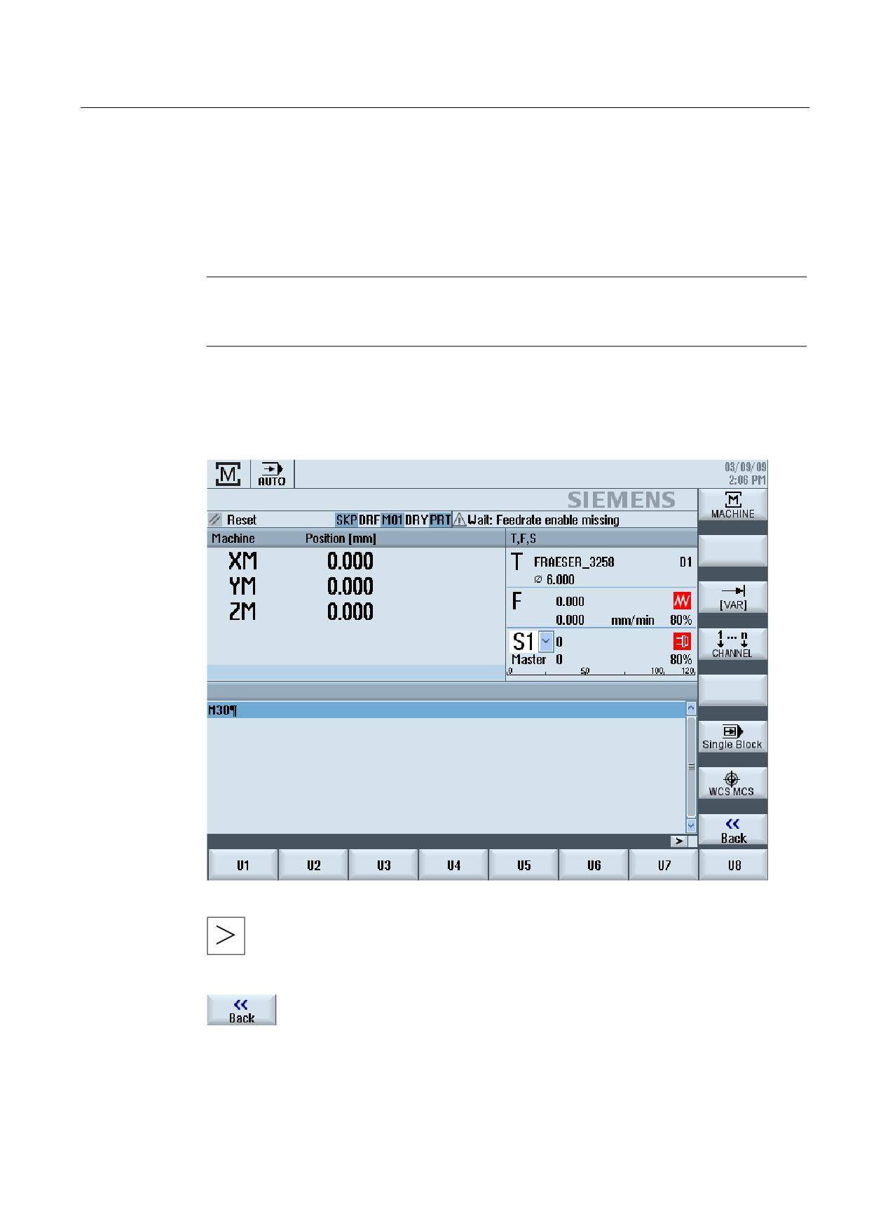
HT 8
11.3 Machine control panel menu
11.3
Machine control panel menu
Here you select keys from the machine control panel which are reproduced by the software
by touch operation of the relevant softkeys.
See chapter "Controls on the machine control panel" for a description of the individual keys.
Note
PLC interface signals that are triggered via the softkeys of the machine control panel menus
are edge triggered.
Showing and hiding
The user menu key "U" displays the CPF softkey bar (vertical softkey bar) and the user
softkey bar (horizontal softkey bar).
You can expand the user softkey bar to display eight additional softkeys via
the menu forward key.
You use the "Back" softkey to hide the menu bar again.
Universal
Operating Manual, 03/2013, 6FC5398-6AP40-3BA1
289
HT 8
11.4 Virtual keyboard
Softkeys on the machine control panel menu
Available softkeys:
"Machine" softkey Select the "Machine" operating area
"[VAR]" softkey
Select the axis feedrate in the variable increment
"1… n CHANNEL"
Change the channel
softkey
"Single Block"
Switch single block execution on/off
softkey
"WCS MCS" softkey Switch between WCS and MCS
"Back" softkey
Close the window.
Note
The window will automatically disappear when changing regions areas with the "Menu
Select" key.
11.4
Virtual keyboard
The virtual keyboard is used as the input device for touch operator panels.
It opens when you double-click an operator element with input capability (editor, edit field).
The virtual keyboard can be positioned anywhere on the operator interface. In addition, you
can toggle between a full keyboard and a reduced keyboard that only includes the number
block. Moreover, with the full keyboard, you can toggle between English key assignments
and the keyboard assignment for the current language setting.
Procedure
1.
Click in the required input field in order to place the cursor there.
2.
Click the input field.
The virtual keyboard is displayed.
3
Enter your values via the virtual keyboard.
4.
Press the <INPUT> key.
- OR -
Position the cursor on an another operator element.
The value is accepted and the virtual keyboard is closed.
Universal
290
Operating Manual, 03/2013, 6FC5398-6AP40-3BA1
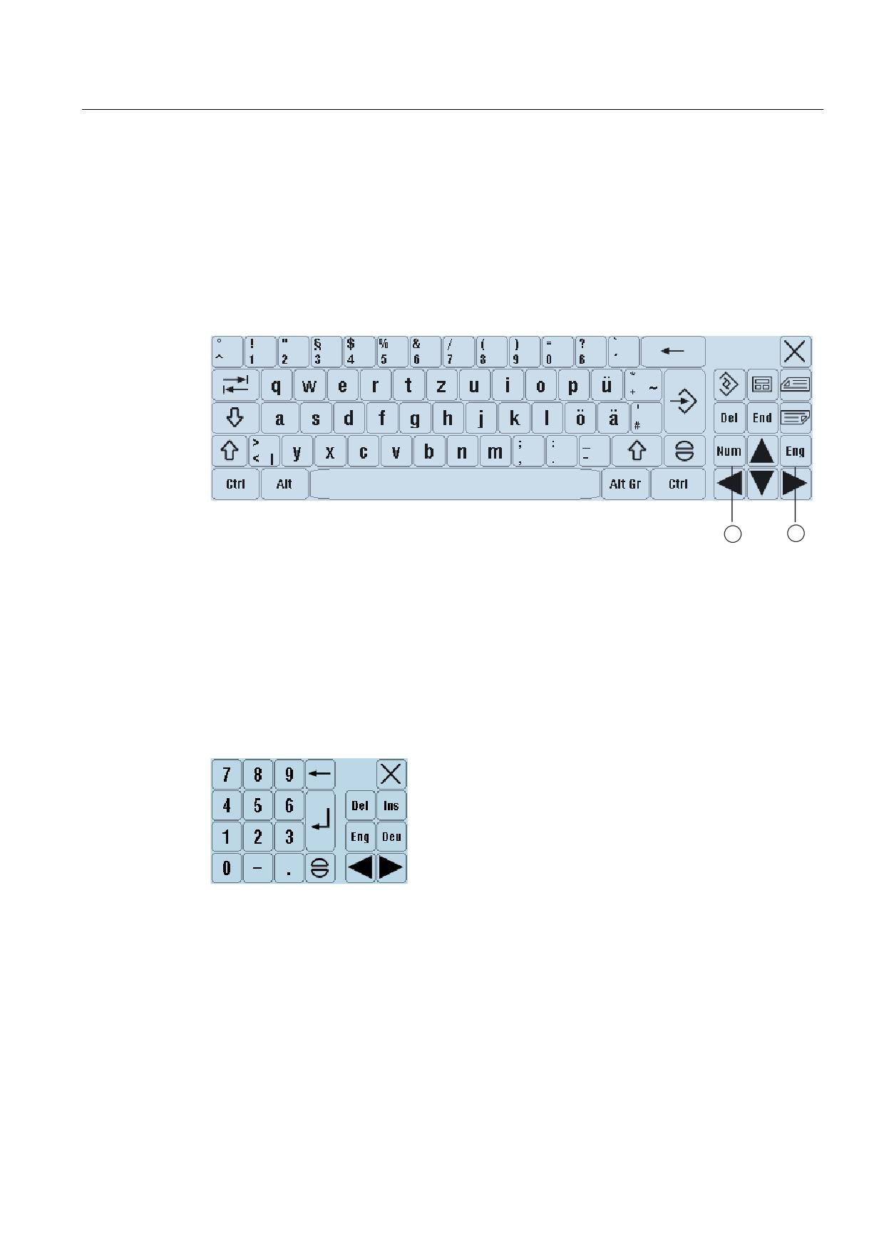
HT 8
11.4 Virtual keyboard
Positioning of the virtual keyboard
You can position the virtual keyboard anywhere in the window by pressing the empty bar
next to the "Close window" icon with your finger or a stylus and moving it back and forth.
Special keys on the virtual keyboard
1
Num:
Reduces the virtual keyboard to the number block.
2
Eng:
Toggles the keyboard assignment between the English keyboard assignment and the
keyboard assignment for the current language setting.
Number block of the virtual keyboard
Use the "Deu" or "Eng" keys to return to the full keyboard with the English keyboard
assignment or the keyboard assignment of the current language setting.
Universal
Operating Manual, 03/2013, 6FC5398-6AP40-3BA1
291
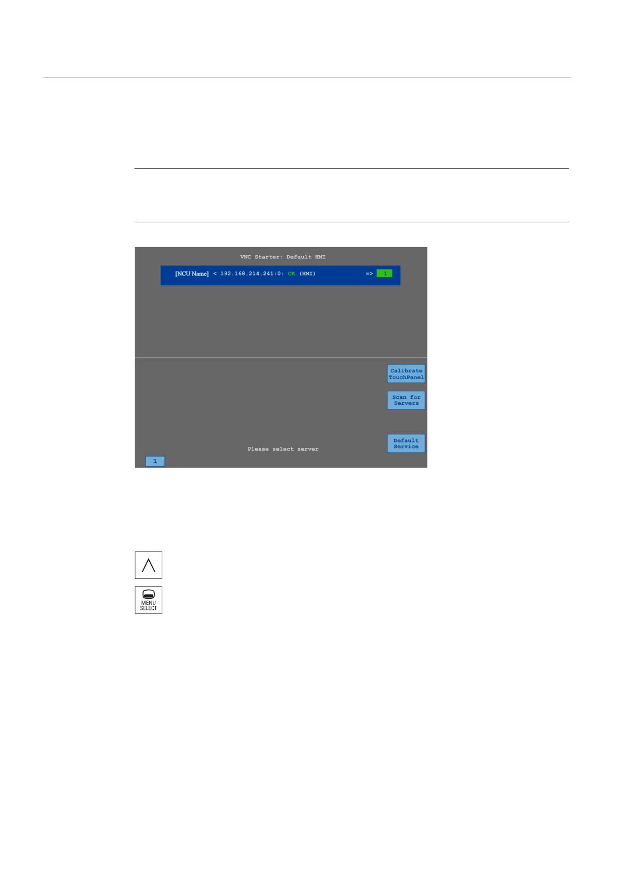
HT 8
11.5 Calibrating the touch panel
11.5
Calibrating the touch panel
It is necessary to calibrate the touch panel upon first connection to the controller.
Note
Recalibration
If the operation is not exact, then redo the calibration.
Procedure
1.
Press the back key and the <MENU SELECT> key at the same time to
start the TCU service screen.
2.
Touch the "Calibrate TouchPanel" button.
The calibration process will be started.
3.
Follow the instructions on the screen and touch the three calibration
points one after the other.
The calibration process has terminated.
4.
Touch the horizontal softkey "1" or the key with the number "1" to close
the TCU service screen.
Universal
292
Operating Manual, 03/2013, 6FC5398-6AP40-3BA1
Ctrl-Energy
12
12.1
Overview
The "Ctrl-Energy" function provides you with the following options to improve the energy
utilization of your machine.
Ctrl-E Analysis: Measuring and evaluating the energy consumption
Acquiring the actual energy consumption is the first step to achieving better energy
efficiency. The energy consumption is measured and displayed at the controller using the
SENTRON PAC multi-function device.
Depending on the configuration and connection of the SENTRON PAC, you have the
possibility of either measuring the power of the whole machine or only a specific load.
Independent of this, the power is determined directly from the drives and displayed.
Ctrl-E Profiles: Control of energy saving states of the machine
To optimize the energy consumption, you have the option of defining energy saving profiles
and saving them. For instance, your machine has a basic and a more sophisticated energy-
saving mode - or under certain conditions, automatically switches itself off.
These defined energy states are saved as profiles. At the user interface, you have the
possibility of activating these energy-saving profiles (e.g. the so-called tea break key).
Note
Ctrl-E Deactivating profiles
Disable Ctrl-E profiles before a series startup in order to prevent the NCU unintentionally
shutting down.
Machine manufacturer
Please refer to the machine manufacturer's specifications.
See also
Using the energy-saving profile (Page 299)
Universal
Operating Manual, 03/2013, 6FC5398-6AP40-3BA1
293
Ctrl-Energy
12.2 Displaying energy consumption
12.2
Displaying energy consumption
You have the option of displaying the actual energy consumption values of the individual
axes and the total energy consumption.
Display
Meaning
Manual
• No input
• Entering and displaying a fixed value
• Displaying a value from a data source
Sentron PAC
Displaying an actual value measured by a SENTRON PAC device.
Total, drives
Display of the total of all measured drive values.
Total, machine
Addition of the values of all axes as well as a fixed value and Sentron
PAC.
The display in the table depends on the configuration.
References
Information on the configuration is provided in the following reference:
System Manual "Ctrl-Energy", SINUMERIK 840D sl / 828D
Procedure
1. Select the "Parameter" operating area and press the "Ctrl-Energy" softkey.
- OR -
+
Press the <Ctrl> + <E> keys.
(
2. Press the "Energy analysis" softkey.
The "SINUMERIK Ctrl-Energy Analysis" window opens.
You obtain a display of the actual active power for all of the axes.
Universal
294
Operating Manual, 03/2013, 6FC5398-6AP40-3BA1
Ctrl-Energy
12.3 Measuring and saving the energy consumption
12.3
Measuring and saving the energy consumption
For the currently selected axes, you have the option of measuring and recording the energy
consumption.
Measurement of the energy consumption by part programs
The energy consumption of part programs can be measured. The measurement should take
single drives into account.
They specify in which channel the start and stop of the part program should be initiated and
which number of repetitions are to be measured.
Save measurements
Save the measured consumption values so that you can subsequently compare the data.
Note
Up to three data records are displayed. The oldest data record is automatically overwritten if
there are more than three measurements.
Measurement duration
The measurement duration is limited. When the maximum measurement duration is reached,
the measurement is terminated and a corresponding message is output in the dialog line.
Machine manufacturer
Please refer to the machine manufacturer's specifications.
Procedure
1.
The "Ctrl-Energy Analysis" window opens.
2.
Press the "Start measurement" softkey.
The "Setting Measurement: Select Device" window opens.
3.
Select the desired device in the list, possibly activate the "Measure part
program" checkbox, enter the number of repetitions, possibly select the
desired channel, and press the "OK" softkey.
The trace is started.
4.
Press the "Stop measurement" softkey.
The measurement is ended.
Universal
Operating Manual, 03/2013, 6FC5398-6AP40-3BA1
295

Ctrl-Energy
12.3 Measuring and saving the energy consumption
5.
Press the "Graphic" softkey, to track the measurement characteristic.
6.
If you want to track the consumption values, press the "Details" softkey.
7.
Press the "Save measurement" softkey to save the consumption values
of the actual measurement.
The selection of the axis to be measured depends on the configuration.
References
Information on the configuration is provided in the following reference:
System Manual "Ctrl-Energy", SINUMERIK 840D sl / 828D
Universal
296
Operating Manual, 03/2013, 6FC5398-6AP40-3BA1
Ctrl-Energy
12.4 Displaying measured curves
12.4
Displaying measured curves
Display
Meaning
Start of the measurement
Shows the time at which the measurement was started by the pressing
the "Start measurement" softkey.
Duration of the
Shows the measuring duration in seconds until the "Stop measurement"
measurement [s]
softkey is pressed.
Device
Displays the selected measured component.
• Manual
• Total, drives
• Total, machine
Supplied energy [kWh]
Shows the supplied energy of the selected measured component in
kilowatts per hour.
Regenerated energy
Shows the regenerated energy of the selected measured component in
[kWh]
kilowatts per hour.
Energy totals [kWh]
Shows the total of all measured drive values or the total of all axes as
well as fixed value and Sentron PAC.
Procedure
1.
The "SINUMERIK Ctrl-Energy Analysis" window opens and you have
already performed and saved measurements.
2.
Press the "Graphic" and "Saved measurements" softkeys.
The measurement curves are displayed in the "SINUMERIK Ctrl-Energy
Analysis" window.
3.
Press the "Saved measurements" softkey again if you only want to see
the actual measurement.
4.
Press the "Details" softkey for the exact measurement data and
consumption values of the last three saved measurements and possibly
a current measurement.
Universal
Operating Manual, 03/2013, 6FC5398-6AP40-3BA1
297
Ctrl-Energy
12.5 Long-term measurement of the energy consumption
12.5
Long-term measurement of the energy consumption
The long-term measurement of energy consumption is performed in the PLC and saved. The
values from times in which the HMI is not active are also recorded.
Measured values
The infeed and regenerative power values as well as the sum of the power are displayed for
the following periods:
● Current and previous day
● Current and previous month
● Current and previous year
Requirement
SENTRON PAC is connected.
Procedure
1.
The "Ctrl-Energy Analysis" window opens.
2.
Press the "Long-term measurement" softkey.
The "SINUMERIK Ctrl-Energy Analysis Long-term Measurement"
window opens.
The results of the long-term measurement are displayed.
4.
Press the "Back" softkey to terminate the long-term measurement.
Universal
298
Operating Manual, 03/2013, 6FC5398-6AP40-3BA1
Ctrl-Energy
12.6 Using the energy-saving profile
12.6
Using the energy-saving profile
In the "SINUMERIK Ctrl-Energy Energy-Saving Profile" window, you can display all of the
defined energy-saving profiles. Here, directly activate the required energy-saving profile - or
inhibit or release profiles.
SINUMERIK Ctrl-Energy energy-saving profiles
Display
Meaning
Energy-saving profile
All energy-saving profiles are listed.
active in [min]
The remaining time up until the defined profile is reached is
displayed.
Note
Disable all energy-saving profiles
For example, in order not to disturb the machine while measurements are being made,
select "Disable all".
Once the pre-warning time of a profile has been reached, an alarm window that shows the
remaining time is displayed. Once the energy-saving mode has been reached, then an
appropriate message is displayed in the alarm line.
Energy-saving profiles
Energy-saving profile
Meaning
Simple energy-saving mode
Machine units that are not required are either throttled or shut down.
(machine standby)
When required, the machine is immediately ready to operate again.
Full energy-saving mode (NC
Machine units that are not required are either throttled or shut down.
standby)
Wait times are incurred at the transition into the ready to operate
state.
Maximum energy-saving
The machine is completely switched-off.
mode (auto shut-off)
Longer wait times are incurred at the transition into the ready to
operate state.
Machine manufacturer
The selection and function of the displayed energy-saving profiles can differ.
Please refer to the machine manufacturer's specifications.
Universal
Operating Manual, 03/2013, 6FC5398-6AP40-3BA1
299