SINUMERIK 840D sl/828D Universal. Operating Manual (2013) - page 1
Un
Preface_______________
1
Introduction__________
2
Setting up the machine____
3
Working in manual mode ___
SINUMERIK
4
Machining the workpiece ___
SINUMERIK 840D sl/828D
5
Simulating machining_____
Universal
6
840D sl)
7
840D sl)
Operating Manual
8
Tool management______
9
Managing programs_____
10
Teaching in a program ____
11
HT 8 _____________
12
Ctrl-Energy__________
13
Easy Message (828D only)__
14
Easy Extend (828D only) ___
15
Service Planner (828D only)_
16
add-on (828D only)
Alarm, error, and system
17
messages__________
A
Valid for:
Appendix___________
Controls
SINUMERIK 840D sl / 840DE sl / 828D
Software
CNC system software for 840D sl/ 840DE sl V4.5 SP2
SINUMERIK Operate
V4.5 SP2
for PCU/PC
03/2013
6FC5398-6AP40-3BA1
Legal information
Warning notice system
This manual contains notices you have to observe in order to ensure your personal safety, as well as to prevent
damage to property. The notices referring to your personal safety are highlighted in the manual by a safety alert
symbol, notices referring only to property damage have no safety alert symbol. These notices shown below are
graded according to the degree of danger.
DANGER
indicates that death or severe personal injury will result if proper precautions are not taken.
WARNING
indicates that death or severe personal injury may result if proper precautions are not taken.
CAUTION
indicates that minor personal injury can result if proper precautions are not taken.
NOTICE
indicates that property damage can result if proper precautions are not taken.
If more than one degree of danger is present, the warning notice representing the highest degree of danger will
be used. A notice warning of injury to persons with a safety alert symbol may also include a warning relating to
property damage.
Qualified Personnel
The product/system described in this documentation may be operated only by personnel qualified for the specific
task in accordance with the relevant documentation, in particular its warning notices and safety instructions.
Qualified personnel are those who, based on their training and experience, are capable of identifying risks and
avoiding potential hazards when working with these products/systems.
Proper use of Siemens products
Note the following:
WARNING
Siemens products may only be used for the applications described in the catalog and in the relevant technical
documentation. If products and components from other manufacturers are used, these must be recommended
or approved by Siemens. Proper transport, storage, installation, assembly, commissioning, operation and
maintenance are required to ensure that the products operate safely and without any problems. The permissible
ambient conditions must be complied with. The information in the relevant documentation must be observed.
Trademarks
All names identified by ® are registered trademarks of Siemens AG. The remaining trademarks in this publication
may be trademarks whose use by third parties for their own purposes could violate the rights of the owner.
Disclaimer of Liability
We have reviewed the contents of this publication to ensure consistency with the hardware and software
described. Since variance cannot be precluded entirely, we cannot guarantee full consistency. However, the
information in this publication is reviewed regularly and any necessary corrections are included in subsequent
editions.
Preface
SINUMERIK documentation
The SINUMERIK documentation is organized in the following categories:
● General documentation
● User documentation
● Manufacturer/service documentation
Additional information
You can find information on the following topics at www.siemens.com/motioncontrol/docu:
● Ordering documentation/overview of documentation
● Additional links to download documents
● Using documentation online (find and search in manuals/information)
Please send any questions about the technical documentation (e.g. suggestions for
improvement, corrections) to the following address:
docu.motioncontrol@siemens.com
My Documentation Manager (MDM)
Under the following link you will find information to individually compile OEM-specific
machine documentation based on the Siemens content:
Training
For information about the range of training courses, refer under:
SITRAIN - Siemens training for products, systems and solutions in automation technology
SinuTrain - training software for SINUMERIK
FAQs
You can find Frequently Asked Questions in the Service&Support pages under Product
Universal
Operating Manual, 03/2013, 6FC5398-6AP40-3BA1
3
Preface
SINUMERIK
You can find information on SINUMERIK under the following link:
Target group
This documentation is intended for users of universal machines running the SINUMERIK
Operate software.
Benefits
The operating manual helps users familiarize themselves with the control elements and
commands. Guided by the manual, users are capable of responding to problems and taking
corrective action.
Standard scope
This documentation describes the functionality of the standard scope. Extensions or changes
made by the machine manufacturer are documented by the machine manufacturer.
Other functions not described in this documentation might be executable in the control.
However, no claim can be made regarding the availability of these functions when the
equipment is first supplied or in the event of servicing.
Furthermore, for the sake of clarity, this documentation does not contain all detailed
information about all types of the product and cannot cover every conceivable case of
installation, operation or maintenance.
Technical Support
You will find telephone numbers for other countries for technical support in the Internet under
Universal
4
Operating Manual, 03/2013, 6FC5398-6AP40-3BA1
Table of contents
Preface
3
1
Introduction
13
1.1
Product overview
13
1.2
Operator panel fronts
14
1.2.1
Overview
14
1.2.2
Keys of the operator panel
16
1.3
Machine control panels
25
1.3.1
Overview
25
1.3.2
Controls on the machine control panel
25
1.4
Operator interface
28
1.4.1
Screen layout
28
1.4.2
Status display
29
1.4.3
Actual value window
32
1.4.4
T,F,S window
33
1.4.5
Current block display
35
1.4.6
Operation via softkeys and buttons
36
1.4.7
Entering or selecting parameters
38
1.4.8
Pocket calculator
40
1.4.9
Context menu
42
1.4.10
Touch operation
42
1.4.11
Changing the user interface language
43
1.4.12
Entering Asian characters
44
1.4.13
Protection levels
46
1.4.14
Online help in SINUMERIK Operate
48
2
Setting up the machine
51
2.1
Switching on and switching off
51
2.2
Approaching a reference point
52
2.2.1
Referencing axes
52
2.2.2
User agreement
53
2.3
Modes of operation
55
2.3.1
General information
55
2.3.2
Modes groups and channels
57
2.3.3
Channel switchover
57
2.4
Settings for the machine
59
2.4.1
Switching over the coordinate system (MCS/WCS)
59
2.4.2
Switching the unit of measurement
60
2.4.3
Setting the zero offset
61
2.5
Zero offsets
63
2.5.1
Display active zero offset
64
2.5.2
Displaying the zero offset "overview"
65
2.5.3
Displaying and editing base zero offset
66
Universal
Operating Manual, 03/2013, 6FC5398-6AP40-3BA1
5
Table of contents
2.5.4
Displaying and editing settable zero offset
67
2.5.5
Displaying and editing details of the zero offsets
68
2.5.6
Deleting a zero offset
69
2.6
Monitoring axis and spindle data
70
2.6.1
Specify working area limitations
70
2.6.2
Editing spindle data
71
2.7
Displaying setting data lists
72
2.8
Handwheel assignment
72
2.9
MDA
75
2.9.1
Loading an MDA program from the Program Manager
75
2.9.2
Saving an MDA program
76
2.9.3
Executing an MDA program
77
2.9.4
Deleting an MDA program
77
3
Working in manual mode
79
3.1
General
79
3.2
Selecting a tool and spindle
79
3.2.1
T, S, M windows
79
3.2.2
Selecting a tool
81
3.2.3
Starting and stopping a spindle manually
81
3.2.4
Position spindle
82
3.3
Traversing axes
84
3.3.1
Traverse axes by a defined increment
84
3.3.2
Traversing axes by a variable increment
85
3.4
Positioning axes
86
3.5
Manual retraction
87
3.6
Default settings for manual mode
89
4
Machining the workpiece
91
4.1
Starting and stopping machining
91
4.2
Selecting a program
93
4.3
Program running-in
94
4.4
Displaying the current program block
95
4.4.1
Current block display
95
4.4.2
Displaying a basic block
96
4.4.3
Display program level
97
4.5
Correcting a program
98
4.6
Repositioning axes
99
4.7
Starting execution at a specific point
101
4.7.1
Use block search
101
4.7.2
Continuing program from search target
103
4.7.3
Simple search target definition
103
4.7.4
Defining an interruption point as search target
104
4.7.5
Entering the search target via search pointer
105
4.7.6
Parameters for block search in the search pointer
106
Universal
6
Operating Manual, 03/2013, 6FC5398-6AP40-3BA1
Table of contents
4.7.7
Block search mode
107
4.8
Controlling the program run
109
4.8.1
Program control
109
4.8.2
Skip blocks
110
4.9
Overstore
112
4.10
Editing a program
113
4.10.1
Searching in programs
114
4.10.2
Replacing program text
115
4.10.3
Copying/pasting/deleting program blocks
117
4.10.4
Renumbering a program
118
4.10.5
Creating a program block
119
4.10.6
Opening additional programs
120
4.10.7
Editor settings
121
4.11
Display and edit user variables
123
4.11.1
Overview
123
4.11.2
R parameters
124
4.11.3
Displaying global user data (GUD)
125
4.11.4
Displaying channel GUDs
126
4.11.5
Displaying local user data (LUD)
127
4.11.6
Displaying program user data (PUD)
128
4.11.7
Searching for user variables
129
4.12
Display G and auxiliary functions
131
4.12.1
Selected G functions
131
4.12.2
All G functions
133
4.12.3
G functions for mold making
134
4.12.4
Auxiliary functions
136
4.13
Displaying status of synchronized actions
137
4.14
Displaying the program runtime and counting workpieces
139
4.15
Setting for automatic mode
140
4.16
Mold making view
142
4.16.1
Mold making view
142
4.16.2
Starting the mold making view
144
4.16.3
Specifically jump to the program block
145
4.16.4
Searching for program blocks
145
4.16.5
Changing the view
146
4.16.5.1
Enlarging or reducing the graphical representation
146
4.16.5.2
Modifying the viewport
147
5
Simulating machining
149
5.1
Overview
149
5.2
Simulation prior to machining of the workpiece
156
5.3
Simultaneous recording prior to machining of the workpiece
157
5.4
Simultaneous recording during machining of the workpiece
158
5.5
Different views of the workpiece
159
5.5.1
Plan view
159
5.5.2
3D view
159
Universal
Operating Manual, 03/2013, 6FC5398-6AP40-3BA1
7
Table of contents
5.5.3
Side view
160
5.6
Editing the simulation display
161
5.6.1
Blank display
161
5.6.2
Showing and hiding the tool path
161
5.7
Program control during simulation
162
5.7.1
Changing the feedrate
162
5.7.2
Simulating the program block by block
163
5.8
Modifying and adapting the simulation graphics
164
5.8.1
Enlarging or reducing the graphical representation
164
5.8.2
Panning a graphical representation
165
5.8.3
Rotating the graphical representation
165
5.8.4
Modifying the viewport
166
5.8.5
Defining cutting planes
167
5.9
Displaying simulation alarms
168
6
Multi-channel view (only 840D sl)
169
6.1
Multi-channel view
169
6.2
Multi-channel view in the "Machine" operating area
169
6.3
Multi-channel view for large operator panels
172
6.4
Setting the multi-channel view
174
7
Collision avoidance (only 840D sl)
177
7.1
Collision monitoring in the machine operator area
177
7.2
Switching the collision avoidance on and off
178
8
Tool management
181
8.1
Lists for the tool management
181
8.2
Magazine management
182
8.3
Tool types
183
8.4
Tool dimensioning
185
8.5
Tool list
191
8.5.1
Tool list
191
8.5.2
Creating a new tool
194
8.5.3
Additional data
195
8.5.4
Managing several cutting edges
197
8.5.5
Deleting a tool
198
8.5.6
Loading and unloading tools
198
8.5.7
Selecting a magazine
200
8.5.8
Code carrier connection (only 840D sl)
201
8.6
Tool wear
204
8.6.1
Reactivating a tool
207
8.7
Tool data OEM
208
8.8
Magazine
209
8.8.1
Position magazine
211
8.8.2
Relocating a tool
212
Universal
8
Operating Manual, 03/2013, 6FC5398-6AP40-3BA1
Table of contents
8.8.3
Unload all tools
213
8.9
Sorting tool management lists
214
8.10
Filtering the tool management lists
215
8.11
Specific search in the tool management lists
216
8.12
Displaying tool details
218
8.13
Changing a tool type
219
8.14
Settings for tool lists
220
9
Managing programs
223
9.1
Overview
223
9.1.1
NC memory
226
9.1.2
Local drive
227
9.1.3
USB drives
228
9.1.4
FTP drive
229
9.2
Opening and closing a program
230
9.3
Executing a program
232
9.4
Creating a directory/program/job list/program list
233
9.4.1
Creating a new directory
233
9.4.2
Creating a new workpiece
234
9.4.3
Creating a new G code program
235
9.4.4
Storing any new file
236
9.4.5
Creating a job list
238
9.4.6
Creating a program list
239
9.5
Creating templates
241
9.6
Searching directories and files
242
9.7
Displaying the program in the Preview
243
9.8
Selecting several directories/programs
244
9.9
Copying and pasting a directory/program
246
9.10
Deleting a directory/program
248
9.11
Changing file and directory properties
249
9.12
Set up drives
250
9.12.1
Overview
250
9.12.2
Setting up drives
251
9.13
Viewing PDF documents
254
9.14
EXTCALL
255
9.15
Backing up data
258
9.15.1
Generating an archive in the Program Manager
258
9.15.2
Generating an archive via the system data
259
9.15.3
Reading in an archive in the Program Manager
261
9.15.4
Read in archive from system data
263
9.16
Setup data
264
9.16.1
Reading-in set-up data
266
Universal
Operating Manual, 03/2013, 6FC5398-6AP40-3BA1
9
Table of contents
9.17
RS-232-C
268
9.17.1
Reading-in and reading-out archives
268
10
Teaching in a program
273
10.1
Overview
273
10.2
General sequence
273
10.3
Inserting a block
274
10.3.1
Input parameters for teach-in blocks
275
10.4
Teach-in via Windows
277
10.4.1
General information
277
10.4.2
Teach in rapid traverse G0
278
10.4.3
Teach in straight G1
278
10.4.4
Teaching in circle intermediate and circle end point CIP
278
10.4.5
Teach-in A spline
279
10.5
Editing a block
281
10.6
Selecting a block
282
10.7
Deleting a block
283
10.8
Settings for teach-in
284
11
HT 8
285
11.1
HT 8 overview
285
11.2
Traversing keys
288
11.3
Machine control panel menu
289
11.4
Virtual keyboard
290
11.5
Calibrating the touch panel
292
12
Ctrl-Energy
293
12.1
Overview
293
12.2
Displaying energy consumption
294
12.3
Measuring and saving the energy consumption
295
12.4
Displaying measured curves
297
12.5
Long-term measurement of the energy consumption
298
12.6
Using the energy-saving profile
299
13
Easy Message (828D only)
301
13.1
Overview
301
13.2
Activating Easy Message
303
13.3
Creating/editing a user profile
304
13.4
Setting-up events
305
13.5
Logging an active user on and off
307
13.6
Displaying SMS logs
308
Universal
10
Operating Manual, 03/2013, 6FC5398-6AP40-3BA1
Table of contents
13.7
Making settings for Easy Message
309
14
Easy Extend (828D only)
311
14.1
Overview
311
14.2
Enabling a device
312
14.3
Activating and deactivating a device
313
14.4
Commissioning Easy Extend
314
15
Service Planner (828D only)
315
15.1
Performing and monitoring maintenance tasks
315
15.2
Set maintenance tasks
317
16
Ladder Viewer and Ladder add-on (828D only)
319
16.1
PLC diagnostics
319
16.2
Structure of the user interface
320
16.3
Control options
321
16.4
Displaying PLC properties
323
16.5
Displaying and editing NC/PLC variables
323
16.6
Displaying and editing PLC signals
324
16.7
Displaying information on the program blocks
325
16.8
Downloading a PLC user program
328
16.9
Editing the local variable table
329
16.10
Creating a new block
330
16.11
Editing block properties
331
16.12
Inserting and editing networks
332
16.13
Editing network properties
334
16.14
Displaying and editing symbol tables
335
16.15
Inserting/deleting a symbol table
336
16.16
Searching for operands
337
16.17
Displaying the network symbol information table
338
16.18
Displaying/canceling the access protection
339
16.19
Displaying cross references
339
17
Alarm, error, and system messages
341
17.1
Displaying alarms
341
17.2
Displaying an alarm log
343
17.3
Displaying messages
344
17.4
Sorting, alarms, faults and messages
345
17.5
PLC and NC variables
346
Universal
Operating Manual, 03/2013, 6FC5398-6AP40-3BA1
11
Table of contents
17.5.1 Displaying and editing PLC and NC variables
346
17.5.2 Saving and loading screen forms
350
17.5.3 Load symbols
351
17.6
Creating screenshots
352
17.7
Version
353
17.7.1
Displaying version data
353
17.7.2
Save information
354
17.8
Logbook
356
17.8.1
Displaying and editing the logbook
357
17.8.2
Making a logbook entry
358
17.9
Remote diagnostics
360
17.9.1
Setting remote access
360
17.9.2
Permit modem
362
17.9.3
Request remote diagnostics
363
17.9.4
Exit remote diagnostics
364
A
Appendix
365
A.1
840D sl documentation overview
365
Index
367
Universal
12
Operating Manual, 03/2013, 6FC5398-6AP40-3BA1
Introduction
1
1.1
Product overview
The SINUMERIK controller is a CNC (Computerized Numerical Controller) for machine tools.
You can use the CNC to implement the following basic functions in conjunction with a
machine tool:
● Creation and adaptation of part programs
● Execution of part programs
● Manual control
● Access to internal and external data media
● Editing of data for programs
● Management of tools, zero points and further user data required in programs
● Diagnostics of controller and machine
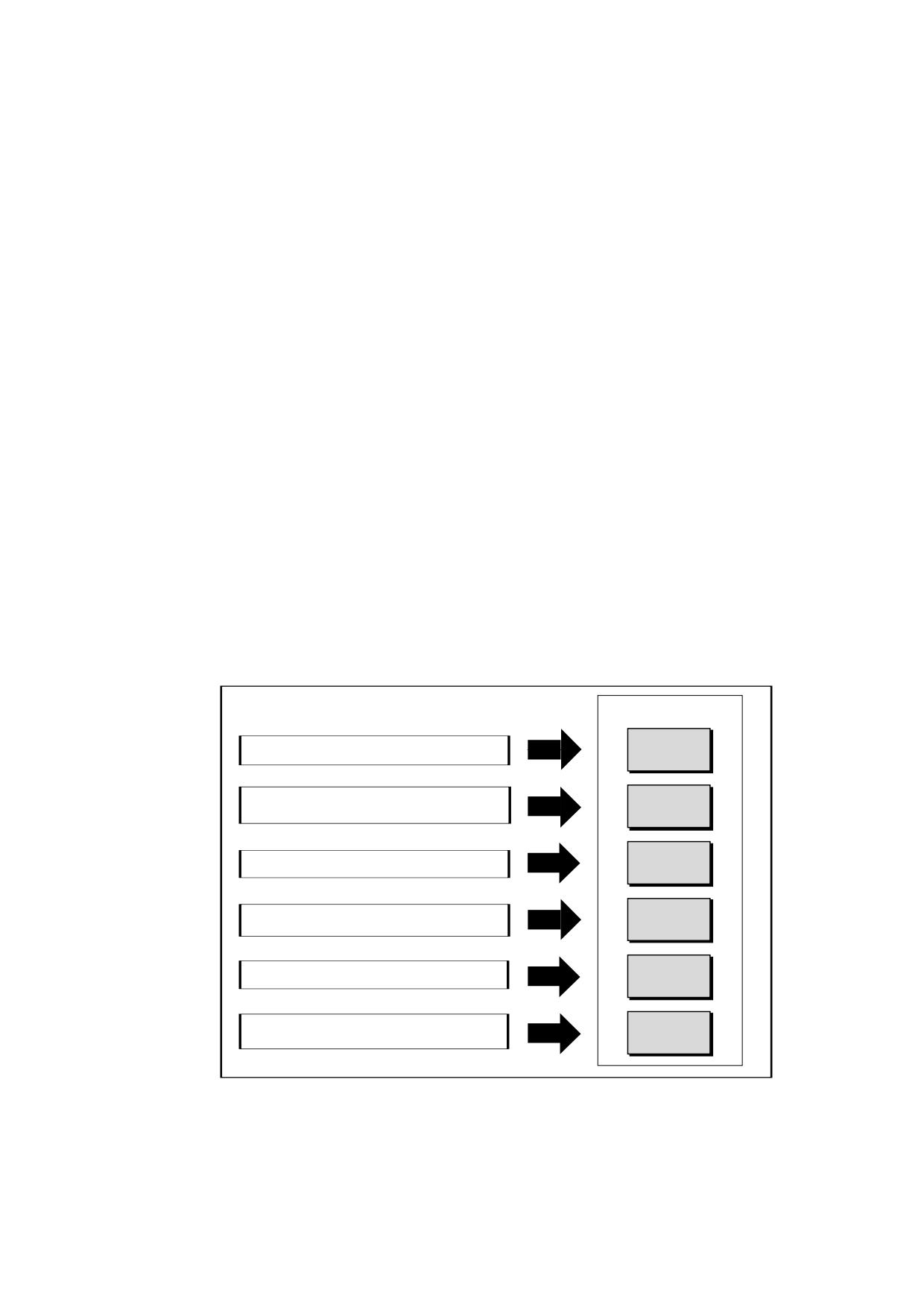
Operating areas
The basic functions are grouped in the following operating areas in the controller:
2SHUDWLQJ DUHDV
([HFXWH SDUW SURJUDPV PDQXDO FRQWURO
0$&+,1(
(GLWLQJ RI GDWD IRU SURJUDPV
3$5$0(7(5
7RRO PDQDJHPHQW
&UHDWLQJ DQG DGDSWLQJ RI SDUW SURJUDPV
352*5$0
352*5$0
$FFHVV WR LQWHUQDO DQG H[WHUQDO GDWD PHGLD
0$1$*(5
$ODUP GLVSOD\ 6HUYLFH GLVSOD\
',$*126,6
$GDSWLQJ RI WKH 1& GDWD WR WKH PDFKLQH
67$57 83
V\VWHP VHWWLQJ
Universal
Operating Manual, 03/2013, 6FC5398-6AP40-3BA1
13
Introduction
1.2 Operator panel fronts
1.2
Operator panel fronts
1.2.1
Overview
Introduction
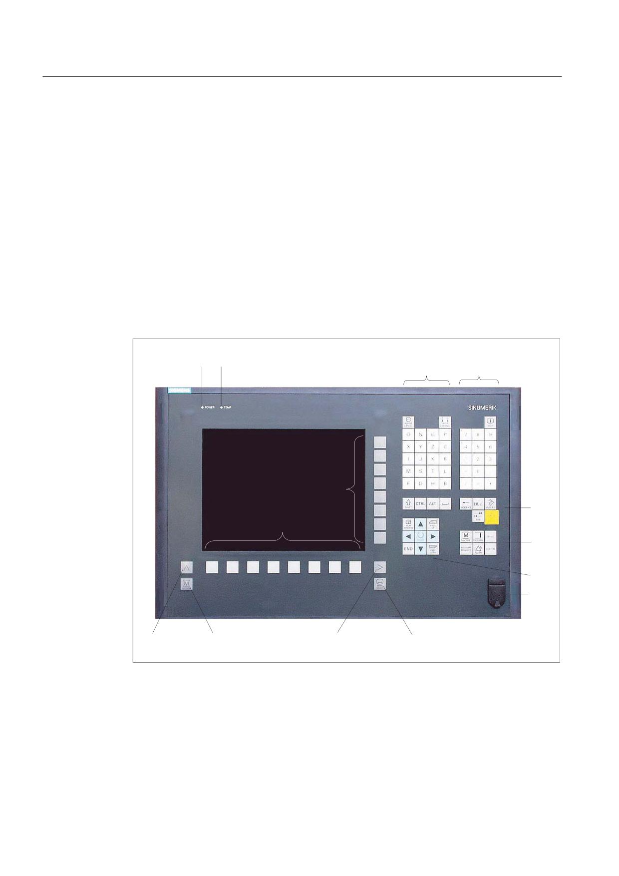
The display (screen) and operation (e.g. hardkeys and softkeys) of the SINUMERIK Operate
user interface use the operator panel front.
In this example, the OP 010 operator panel front is used to illustrate the components that are
available for operating the controller and machine tool.
Operator controls and indicators
(5)
(5)
1
Status LED: POWER
2
Status LED: TEMP
(illuminated LEDs indicate increased wear)
3
Alphabetic key group
4
Numerical key group
5
Softkeys
Universal
14
Operating Manual, 03/2013, 6FC5398-6AP40-3BA1
Introduction
1.2 Operator panel fronts
6
Control key group
7
Hotkey group
8
Cursor key group
9
USB interface
10
Menu select key
11
Menu forward button
12
Machine area button
13
Menu back key
Figure 1-1
View of OP 010 operator panel front
References
A more precise description as well as a view of the other operator panel fronts that can be
used may be found in the following reference:
Operator Components and Networking Manual; SINUMERIK 840D sl/840Di sl
Universal
Operating Manual, 03/2013, 6FC5398-6AP40-3BA1
15
Introduction
1.2 Operator panel fronts
1.2.2
Keys of the operator panel
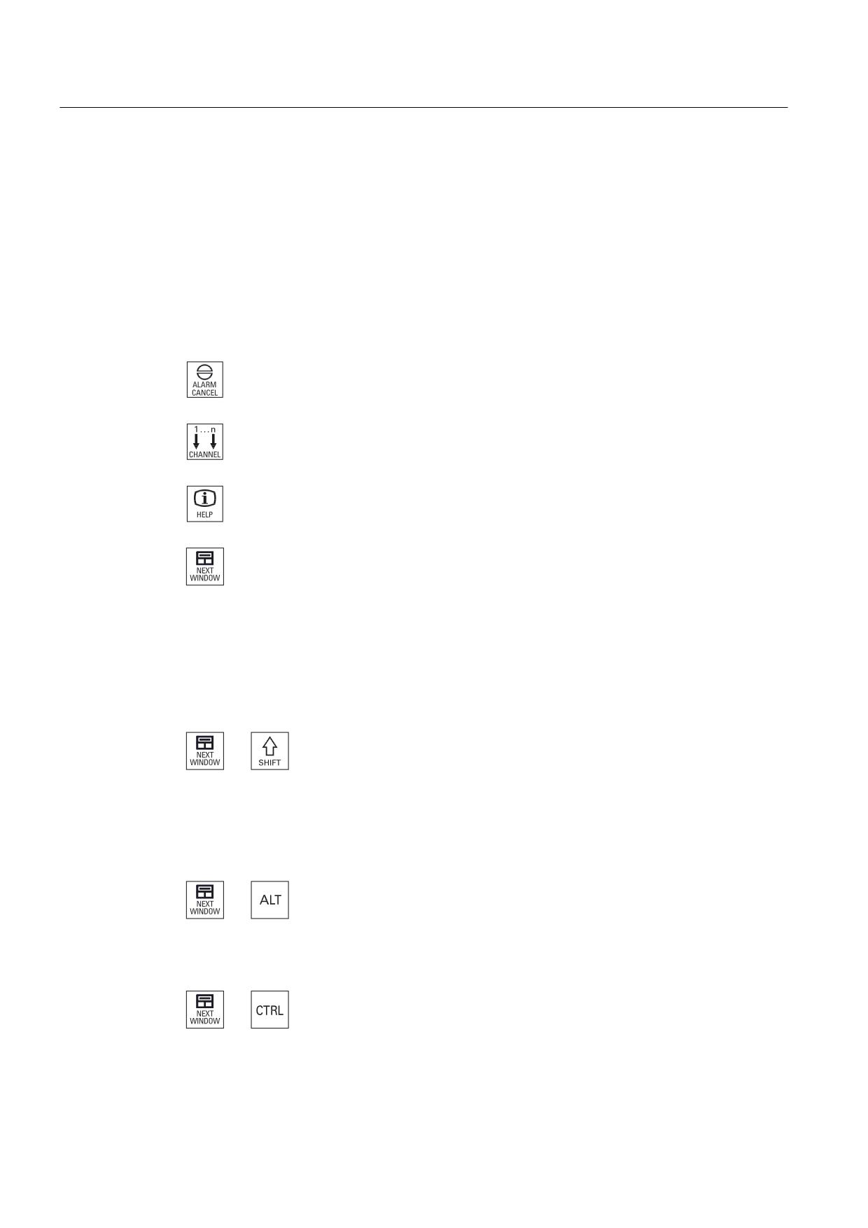
The following keys and key combinations are available for operation of the controller and the
machine tool.
Keys and key combinations
Key
Function
<ALARM CANCEL>
Cancels alarms and messages that are marked with this symbol.
<CHANNEL>
Advances for several channels.
<HELP>
Calls the context-sensitive online help for the selected window.
<NEXT WINDOW> *
• Toggles between the windows.
• For a multi-channel view or for a multi-channel functionality,
switches within a channel gap between the upper and lower
window.
• Selects the first entry in selection lists and in selection fields.
• Moves the cursor to the beginning of a text.
* on USB keyboards use the <Home> or <Pos 1> key
<NEXT WINDOW> + <SHIFT>
• Selects the first entry in selection lists and in selection fields.
• Moves the cursor to the beginning of a text.
• Selects a contiguous selection from the current cursor position
up to the target position.
• Selects a contiguous selection from the current cursor position
up to the beginning of a program block.
<NEXT WINDOW> + <ALT>
• Moves the cursor to the first object.
• Moves the cursor in the first column of a table row.
• Moves the cursor to the beginning of a program block.
<NEXT WINDOW> + <CTRL>
• Moves the cursor to the beginning of a program.
• Moves the cursor in the first row of the current column.
Universal
16
Operating Manual, 03/2013, 6FC5398-6AP40-3BA1
Introduction
1.2 Operator panel fronts
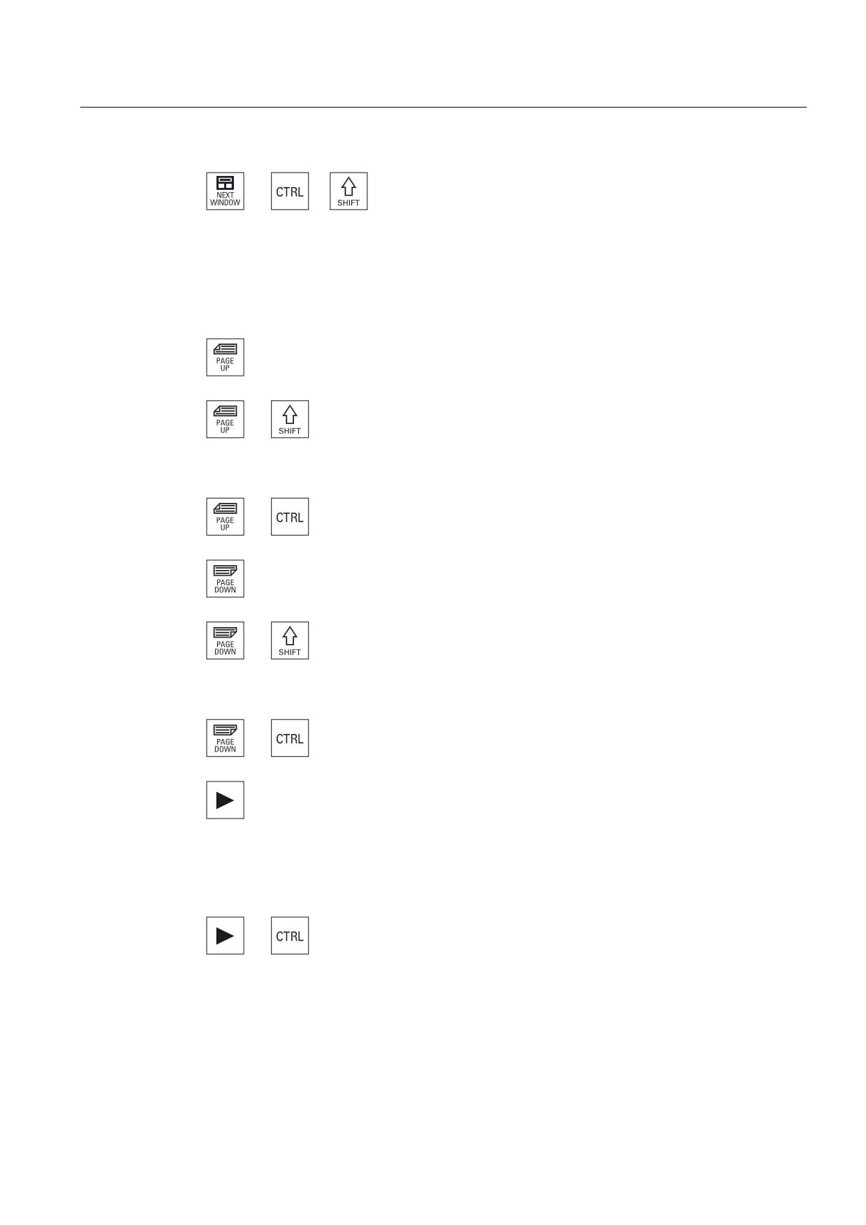
<NEXT WINDOW> + <CTRL> + <SHIFT>
• Moves the cursor to the beginning of a program.
• Moves the cursor in the first row of the current column.
• Selects a contiguous selection from the current cursor position
up to the target position.
• Selects a contiguous selection from the current cursor position
up to the beginning of the program.
<PAGE UP>
Scrolls upwards by one page in a window.
<PAGE UP> + <SHIFT>
In the program manager and in the program editor from the cursor
position, selects directories or program blocks up to the beginning
of the window.
<PAGE UP> + <CTRL>
Positions the cursor to the topmost line of a window.
<PAGE DOWN>
Scrolls downwards by one page in a window.
<PAGE DOWN> + <SHIFT>
In the program manager and in the program editor, from the cursor
position, selects directories or program blocks up to the end of the
window.
<PAGE DOWN> + <CTRL>
Positions the cursor to the lowest line of a window.
<Cursor right>
• Editing box
Opens a directory or program (e.g. cycle) in the editor.
• Navigation
Moves the cursor further to the right by one character.
<Cursor right> + <CTRL>
• Editing box
Moves the cursor further to the right by one word.
• Navigation
Moves the cursor in a table to the next cell to the right.
Universal
Operating Manual, 03/2013, 6FC5398-6AP40-3BA1
17
Introduction
1.2 Operator panel fronts
<Cursor left>
• Editing box
Closes a directory or program (e.g. cycle) in the program editor.
If you have made changes, then these are accepted.
• Navigation
Moves the cursor further to the left by one character.
<Cursor left> + <CTRL>
• Editing box
Moves the cursor further to the left by one word.
• Navigation
Moves the cursor in a table to the next cell to the left.
<Cursor up>
• Editing box
Moves the cursor into the next upper field.
• Navigation
- Moves the cursor in a table to the next cell upwards.
- Moves the cursor upwards in a menu screen.
<Cursor up> + <CTRL>
• Moves the cursor in a table to the beginning of the table.
• Moves the cursor to the beginning of a window.
<Cursor up> + <SHIFT>
In the program manager and in the program editor, selects a
contiguous selection of directories and program blocks.
<Cursor down>
• Editing box
Moves the cursor downwards.
• Navigation
- Moves the cursor in a table to the next cell downwards.
- Moves the cursor in a window downwards.
<Cursor down> + <CTRL>
• Navigation
- Moves the cursor in a table to the end of the table.
- Moves the cursor to the end of a window.
• Simulation
Reduces the override.
Universal
18
Operating Manual, 03/2013, 6FC5398-6AP40-3BA1
Introduction
1.2 Operator panel fronts
<Cursor down> + <SHIFT>
In the program manager and in the program editor, selects a
contiguous selection of directories and program blocks.
<SELECT>
Switches between several specified options in selection drop-down
list boxes and in selection boxes.
Activates checkboxes.
In the program editor and in the program manager, selects a
program block or a program.
<SELECT> + <CTRL>
When selecting table rows, switches between selected and not
selected.
<SELECT> + <SHIFT>
Selects in selection lists and in selection fields the previous entry
or the last entry.
<END>
Moves the cursor to the last entry field in a window, to the end of a
table or a program block.
Selects the last entry in selection lists and in selection fields.
<END> + <SHIFT>
Moves the cursor to the last entry.
Selects a contiguous selection from the cursor position up to the
end of a program block.
<END> + <CTRL>
Moves the cursor to the last entry in the last line of the actual
column or to the end of a program.
<END> + <CTRL> + <SHIFT>
Moves the cursor to the last entry in the last line of the actual
column or to the end of a program.
Selects a contiguous selection from the cursor position up to the
end of a program block.
<BACKSPACE>
• Editing box
Deletes a character selected to the left of the cursor.
• Navigation
Deletes all of the selected characters to the left of the cursor.
Universal
Operating Manual, 03/2013, 6FC5398-6AP40-3BA1
19
Introduction
1.2 Operator panel fronts
<BACKSPACE> + <CTRL>
• Editing window
Deletes a word selected to the left of the cursor.
• Navigation
Deletes all of the selected characters to the left of the cursor.
<TAB>
• In the program editor, indents the cursor by one character.
• In the program manager, moves the cursor to the next entry to
the right.
<TAB> + <SHIFT>
• In the program editor, indents the cursor by one character.
• In the program manager, moves the cursor to the next entry to
the left.
<TAB> + <CTRL>
• In the program editor, indents the cursor by one character.
• In the program manager, moves the cursor to the next entry to
the right.
<TAB> + <SHIFT> + <CTRL>
• In the program editor, indents the cursor by one character.
• In the program manager, moves the cursor to the next entry to
the left.
<CTRL> + <A>
$
In the actual window, selects all entries (only in the program editor
and program manager).
<CTRL> + <C>
&
Copies the selected content.
<CTRL> + <E>
(
Calls the "Ctrl Energy" function.
<CTRL> + <F>
)
Opens the search dialog in the machine data and setting data lists,
when loading and saving in the MDI editor as well as in the
program manager and in the system data.
<CTRL> + <G>
*
• Switches in the program editor for ShopMill or ShopTurn
programs between the work plan and the graphic view.
• Switches in the the parameter screen between the help display
and the graphic view.
Universal
20
Operating Manual, 03/2013, 6FC5398-6AP40-3BA1
Introduction
1.2 Operator panel fronts
<CTRL> + <L>
/
Scrolls the actual user interface through all installed languages one
after the other.
<CTRL> + <SHIFT> + <L>
/
Scrolls the actual user interface through all installed languages in
the inverse sequence.
<CTRL> + <P>
3
Generates a screenshot from the actual user interface and saves it
as file.
<CTRL> + <S>
6
Switches the single block in or out in the simulation.
<CTRL> + <V>
9
• Pastes text from the clipboard at the actual cursor position.
• Pastes text from the clipboard at the position of a selected text.
<CTRL> + <X>
;
Cuts out the selected text. The text is located in the clipboard.
<CTRL> + <Y>
<
Reactivates changes that were undone (only in the program
editor).
<CTRL> + <Z>
=
Undoes the last action (only in the program editor).
<CTRL> + <ALT> + <C>
&
Creates a complete standard archive (.ARC) on an external data
carrier (USB-FlashDrive) (for 840D sl / 828D).
Note:
Please refer to the machine manufacturer's specifications.
<CTRL> + <ALT> + <S>
6
Creates a complete standard archive (.ARC) on an external data
carrier (USB-FlashDrive) (for 840D sl).
Creates a complete Easy Archive (.ARD) on an external data
carrier (USB-FlashDrive) (for 828D).
Note:
Please refer to the machine manufacturer's specifications.
<CTRL> + <ALT> + <D>
'
Backs up the log files on the USB-FlashDrive. If a USB-FlashDrive
is not inserted, then the files are backed-up in the manufacturer's
area of the CF card.
Universal
Operating Manual, 03/2013, 6FC5398-6AP40-3BA1
21
Introduction
1.2 Operator panel fronts
<SHIFT> + <ALT> + <D>
'
Backs up the log files on the USB-FlashDrive. If a USB-FlashDrive
is not inserted, then the files are backed-up in the manufacturer's
area of the CF card.
<SHIFT> + <ALT> + <T>
7
Starts "HMI Trace".
<SHIFT> + <ALT> + <T>
7
Exits "HMI Trace".
<ALT> + <S>
6
Opens the editor to enter Asian characters.
<ALT> + <Cursor up>
Moves the block start or block end up in the editor.
<ALT> + <Cursor down>
Moves the block start or block end down in the editor.
<DEL>
• Editing box
Deletes the first character to the right of the cursor.
• Navigation
Deletes all characters.
<DEL> + <CTRL>
• Editing box
Deletes the first word to the right of the cursor.
• Navigation
Deletes all characters.
<Spacebar>
• Editing window
Inserts a space
• Switches between several specified options in selection drop-
down list boxes and in selection boxes.
<Plus>
• Opens a directory which contains the element.
• Increases the size of the graphic view for simulation and traces.
Universal
22
Operating Manual, 03/2013, 6FC5398-6AP40-3BA1
Introduction
1.2 Operator panel fronts
<Minus>
• Closes a directory which contains the element.
• Reduces the size of the graphic view for simulation and traces.
<Equals>
Opens the calculator in the entry fields.
<Asterisk>
Opens a directory with all of the subdirectories.
<Tilde>
a
Changes the sign of a number between plus and minus.
<INSERT>
• Opens an editing window in the insert mode. Pressing the key
again, exits the window and the entries are undone.
• Opens a selection box and shows the selection possibilities.
• In the machining step program, enters an empty line for G code.
• Changes into the double editor or into the multi-channel view
from the edit mode into the operating mode. You can return to
the edit mode by pressing the key again.
+
<INSERT> + <SHIFT>
For G code programming, for a cycle call activates or deactivates
the edit mode.
<INPUT>
• Completes input of a value in the entry field.
• Opens a directory or a program.
• Inserts an empty program block if the cursor is positioned at the
end of a program block.
• Inserts a character to select a new line and the program block is
split up into two parts.
• In the G code, inserts a new line after the program block.
• In the machining step program, inserts a new line for G code e
• Changes into the double editor or into the multi-channel view
from the edit mode into the operating mode. You can return to
the edit mode by pressing the key again.
<ALARM> - only OP 010 and OP 010C
Calls the "Diagnosis" operating area.
<PROGRAM> - only OP 010 and OP 010C
Calls the "Program Manager" operating area.
Universal
Operating Manual, 03/2013, 6FC5398-6AP40-3BA1
23
Introduction
1.2 Operator panel fronts
<OFFSET> - only OP 010 and OP 010C
Calls the "Parameter" operating area.
<PROGRAM MANAGER> - only OP 010 and OP 010C
Calls the "Program Manager" operating area.
Menu forward key
Advances in the extended horizontal softkey bar.
Menu back key
Returns to the higher-level menu.
<MACHINE>
Calls the "Machine" operating area.
<MENU SELECT>
Calls the main menu to select the operating area.
Universal
24
Operating Manual, 03/2013, 6FC5398-6AP40-3BA1
Introduction
1.3 Machine control panels
1.3
Machine control panels
1.3.1
Overview
The machine tool can be equipped with a machine control panel by Siemens or with a
specific machine control panel from the machine manufacturer.
You use the machine control panel to initiate actions on the machine tool such as traversing
an axis or starting the machining of a workpiece.
1.3.2
Controls on the machine control panel
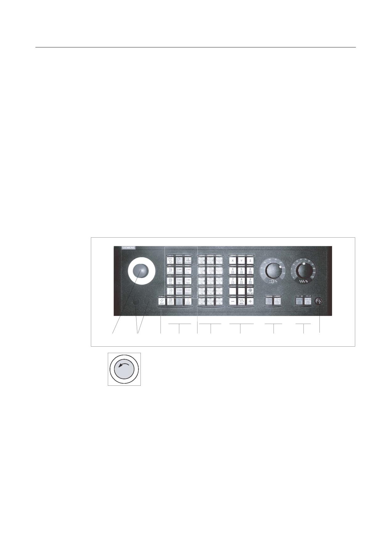
In this example, the MCP 483C IE machine control panel is used to illustrate the operator
controls and displays of a Siemens machine control panel.
Overview
(1)
EMERGENCY STOP button
Activate the button in situations where
• life is at risk.
• there is the danger of a machine or workpiece being damaged.
All drives will be stopped with the greatest possible braking torque.
Universal
Operating Manual, 03/2013, 6FC5398-6AP40-3BA1
25
Introduction
1.3 Machine control panels
Machine manufacturer
For additional responses to pressing the Emergency Stop button, please
refer to the machine manufacturer's instructions.
(2)
Installation locations for control devices (d = 16 mm)
(3)
RESET
• Stop processing the current programs.
The NCK control remains synchronized with the machine. It is in its initial
state and ready for a new program run.
• Cancel alarm.
(4)
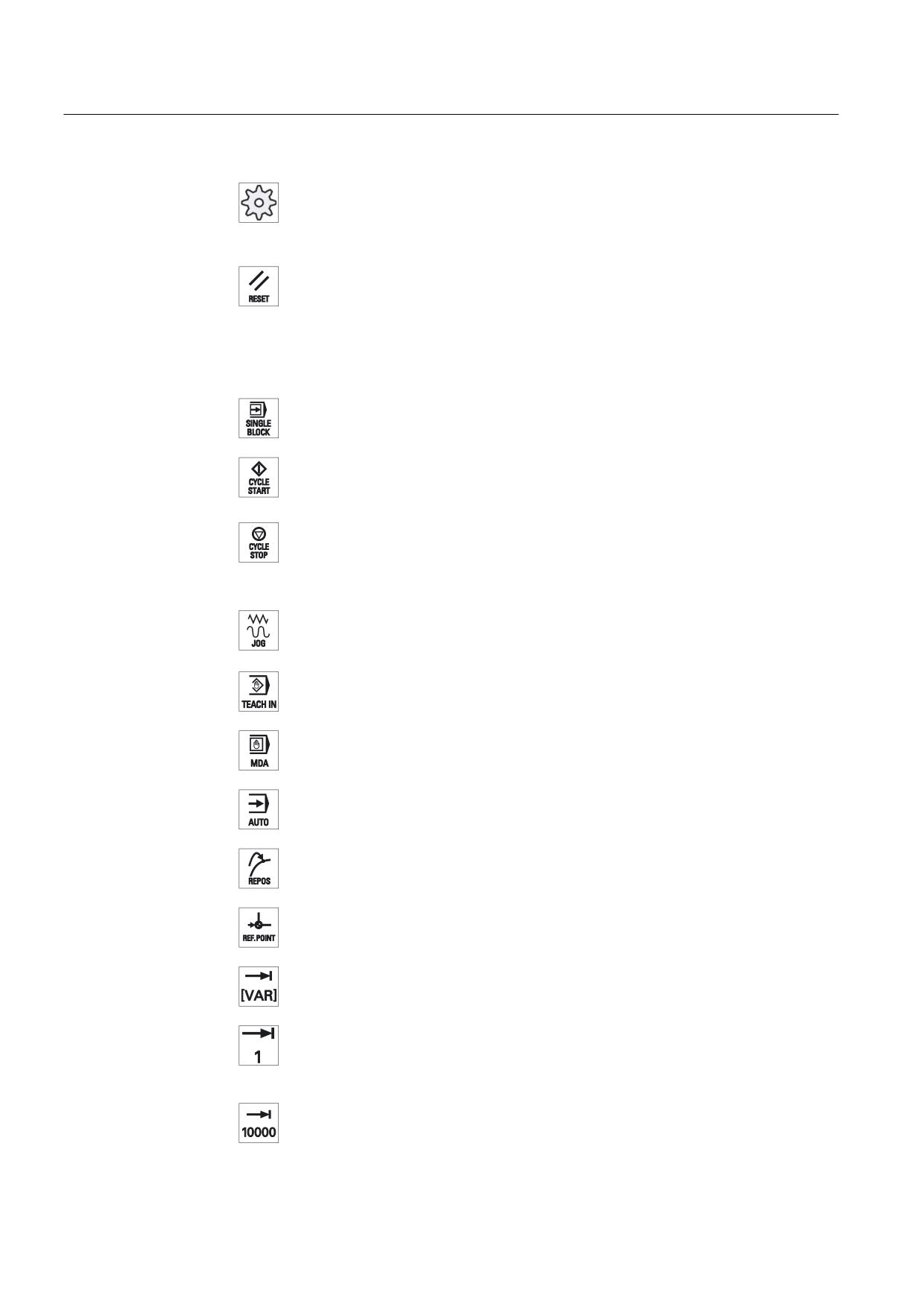
Program control
<SINGLE BLOCK>
Single block mode on/off.
<CYCLE START>
The key is also referred to as NC Start.
Execution of a program is started.
<CYCLE STOP>
The key is also referred to as NC Stop.
Execution of a program is stopped.
(5)
Operating modes, machine functions
<JOG>
Select "JOG" mode.
<TEACH IN>
Select "Teach In" submode.
<MDI>
Select "MDI" mode.
<AUTO>
Select "AUTO" mode.
<REPOS>
Repositions, re-approaches the contour.
<REF POINT>
Approach reference point.
Inc <VAR>(Incremental Feed Variable)
Incremental mode with variable increment size.
Inc (incremental feed)
Incremental mode with predefined increment size of 1, ..., 10000
increments.
Universal
26
Operating Manual, 03/2013, 6FC5398-6AP40-3BA1
Introduction
1.3 Machine control panels
Machine manufacturer
A machine data code defines how the increment value is
interpreted.
(6)
Customer keys
T1 to T15
(7)
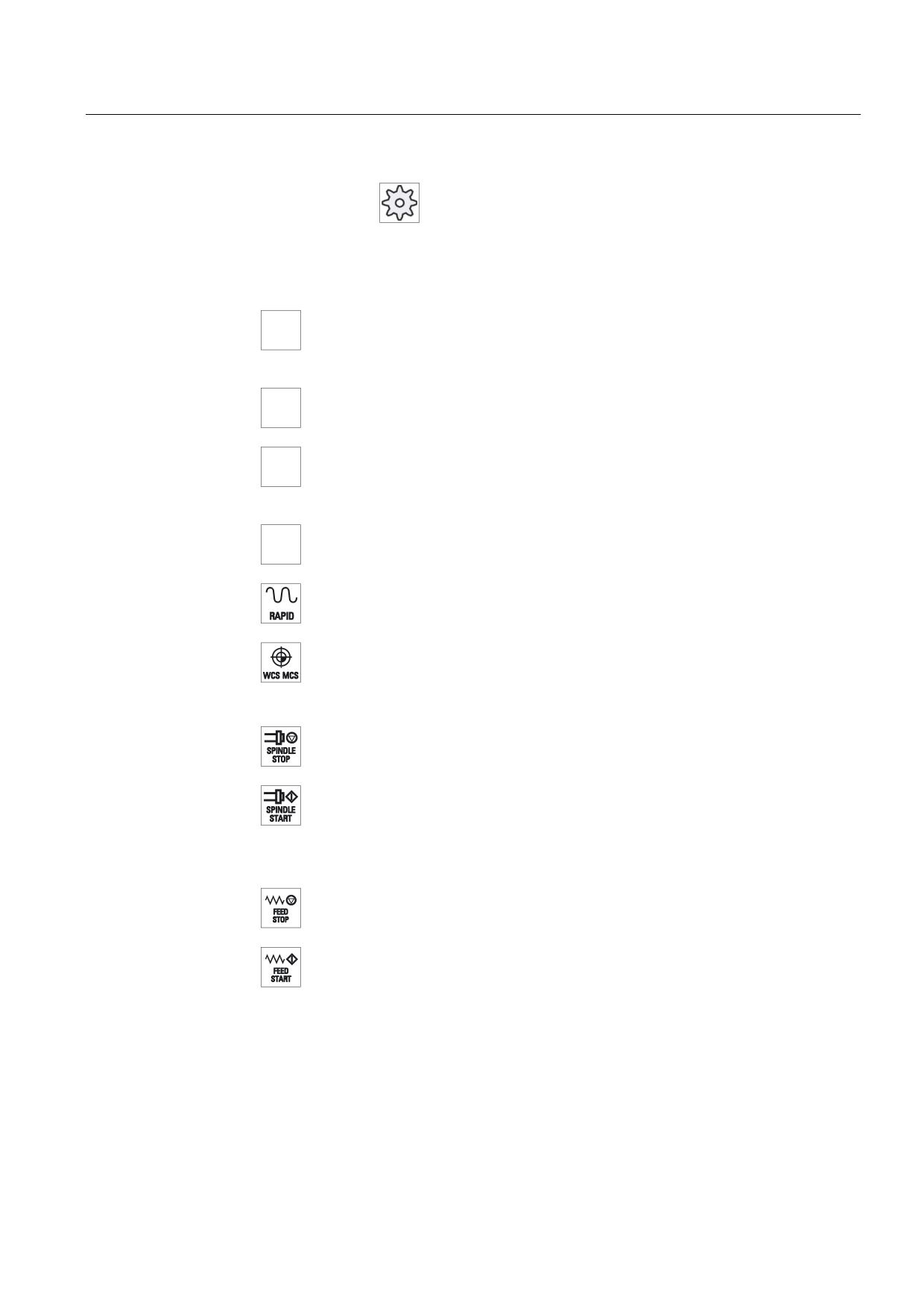
Traversal axes with rapid traverse superposition and coordinate exchange
Axis keys
;
Selects an axis.
=
Direction keys
Select the traversing direction.
<RAPID>
Traverse axis in rapid traverse while pressing the direction key.
<WCS MCS>
Switches between the workpiece coordinate system (WCS) and machine
coordinate system (MCS).
(8)
Spindle control with override switch
<SPINDLE STOP>
Stop spindle.
<SPINDLE START>
Spindle is enabled.
(9)
Feed control with override switch
<FEED STOP>
Stops execution of the running program and shuts down axis drives.
<FEED START>
Enable for program execution in the current block and enable for ramp-up to
the feedrate value specified by the program.
(10)
Keyswitch (four positions)
Figure 1-2
Front view of machine control panel (milling version)
Universal
Operating Manual, 03/2013, 6FC5398-6AP40-3BA1
27
Introduction
1.4 Operator interface
1.4
Operator interface
1.4.1
Screen layout
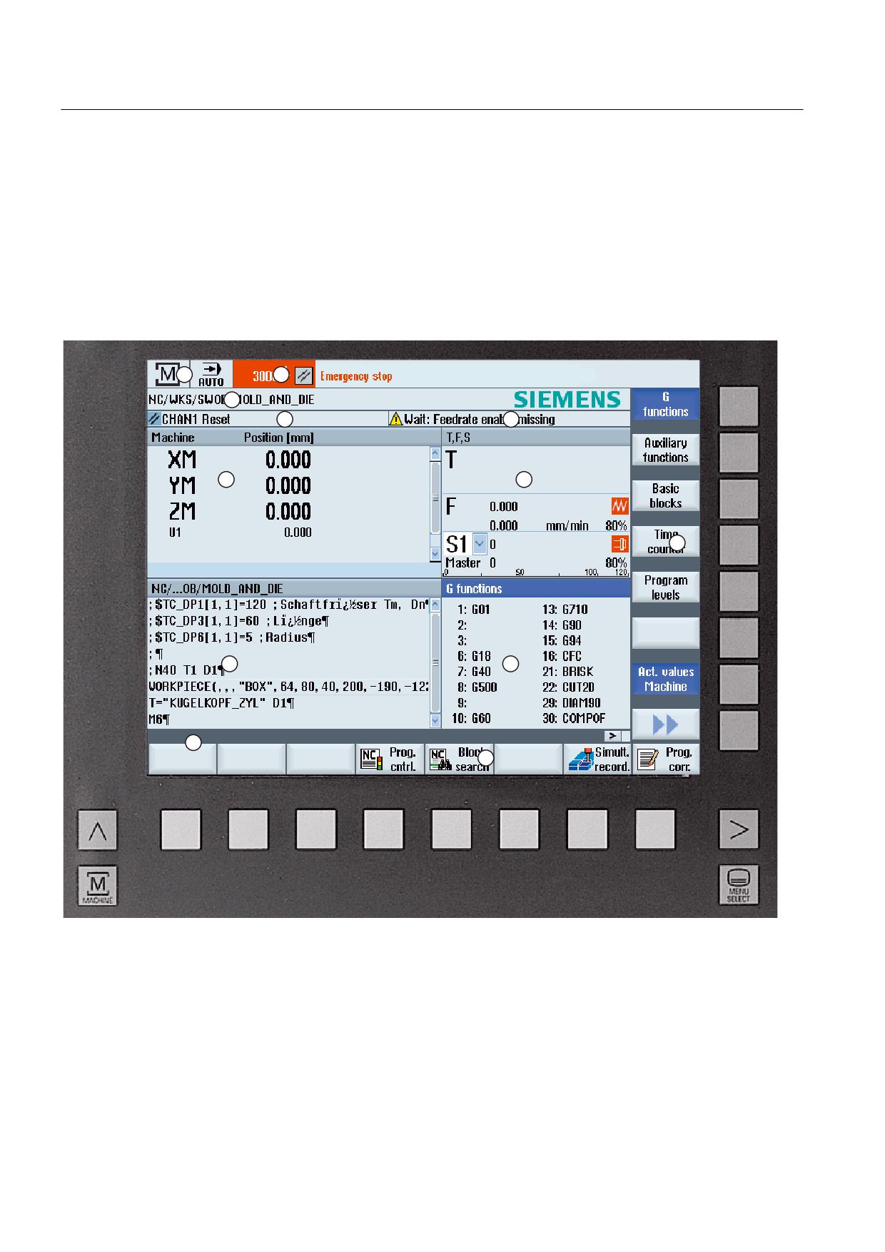
Overview
1
Active operating area and mode
2
Alarm/message line
3
Program name
4
Channel state and program control
5
Channel operational messages
6
Axis position display in actual value window
Universal
28
Operating Manual, 03/2013, 6FC5398-6AP40-3BA1
Introduction
1.4 Operator interface
7
Display for
• Active tool T
• Current feedrate F
• Active spindle with current status (S)
• Spindle utilization rate in percent
• Name of the active tool carrier with display of a rotation in space and plane
• Name of the active kinematic transformation
8
Operating window with program block display
9
Display of active G functions, all G functions, auxiliary functions and input window for different functions (for
example, skip blocks, program control).
10
Dialog line to provide additional user notes.
11
Horizontal softkey bar
12
Vertical softkey bar
Figure 1-3
User interface
1.4.2
Status display
The status display includes the most important information about the current machine status
and the status of the NCK. It also shows alarms as well as NC and PLC messages.
Depending on your operating area, the status display is made up of several lines:
● Large status display
The status display is made up of three lines in the "Machine" operating area.
● Small status display
In the "Parameter", "Program", "Program Manager", "Diagnosis" and "Start-up" operating
areas, the status display consists of the first line from the large display.
Status display of "Machine" operating area
First line
Display
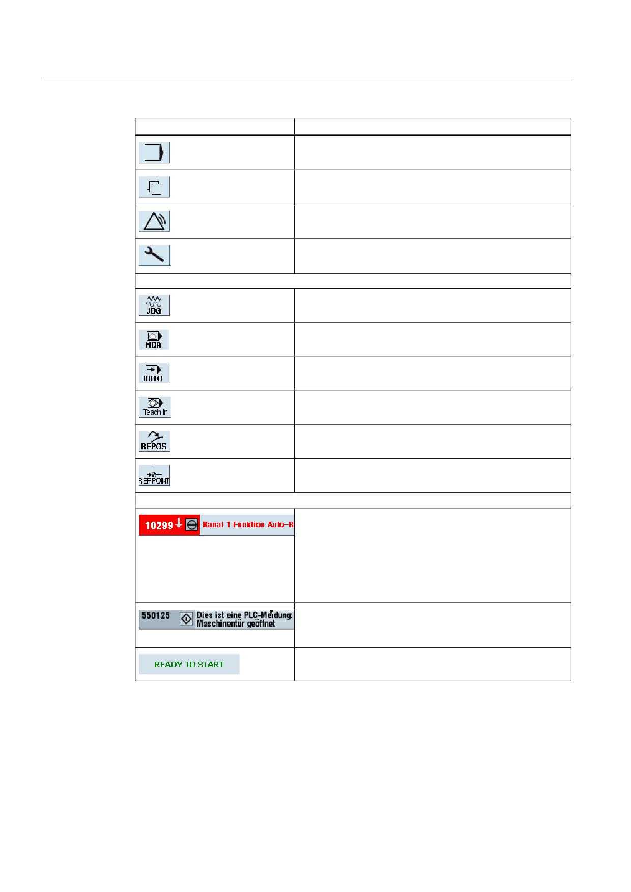
Description
Active operating area
"Machine" operating area
With touch operation, you can change the operating area here.
"Parameter" operating area
Universal
Operating Manual, 03/2013, 6FC5398-6AP40-3BA1
29
Introduction
1.4 Operator interface
Display
Description
"Program" operating area
"Program manager" operating area
"Diagnosis" operating area
"Start-up" operating area
Active mode or submode
"Jog" mode
"MDA" mode
"Auto" mode
"Teach In" submode
"Repos" submode
"Ref Point" submode
Alarms and messages
Alarm display
The alarm numbers are displayed in white lettering on a red
backg0round. The associated alarm text is shown in red
lettering.
An arrow indicates that several alarms are active.
An acknowledgment symbol indicates that the alarm can be
acknowledged or canceled.
NC or PLC message
Message numbers and texts are shown in black lettering.
An arrow indicates that several messages are active.
Messages from NC programs do not have numbers and appear
in green lettering.
Universal
30
Operating Manual, 03/2013, 6FC5398-6AP40-3BA1
Introduction
1.4 Operator interface
Second line
Display
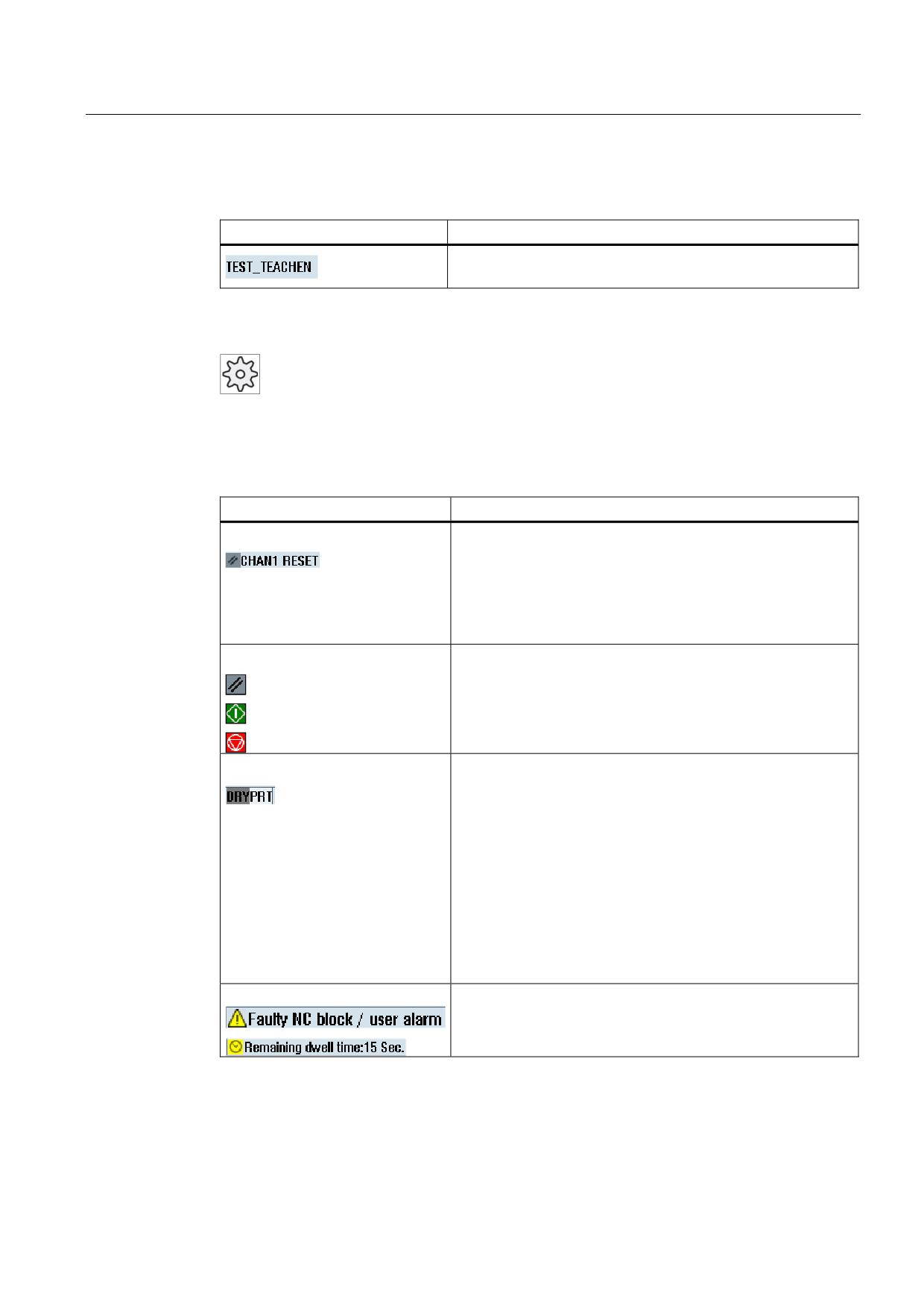
Description
Program path and program name
The displays in the second line can be configured.
Machine manufacturer
Please also refer to the machine manufacturer's instructions.
Third line
Display
Description
Display of channel status.
If several channels are present on the machine, the channel
name is also displayed.
If only one channel is available, only the "Reset" channel status
is displayed.
With touch operation, you can change the channel here.
Display of channel status:
The program was aborted with "Reset".
The program is started.
The program has been interrupted with "Stop".
Display of active program controls:
PRT: no axis motion
DRY: Dry run feedrate
RG0: reduced rapid traverse
M01: programmed stop 1
M101: programmed stop 2 (name varies)
SB1: Single block, coarse (program stops only after blocks
which perform a machine function)
SB2: Data block (program stops after each block)
SB3: Single block, fine (program also only stops after blocks
which perform a machine function in cycles)
Channel operational messages:
Stop: An operator action is usually required.
Wait: No operator action is required.
The machine manufacturer settings determine which program controls are displayed.
Universal
Operating Manual, 03/2013, 6FC5398-6AP40-3BA1
31
Introduction
1.4 Operator interface
Machine manufacturer
Please also refer to the machine manufacturer's instructions.
1.4.3
Actual value window
The actual values of the axes and their positions are displayed.
Work/Machine
The displayed coordinates are based on either the machine coordinate system or the
workpiece coordinate system. The machine coordinate system (Machine), in contrast to the
workpiece coordinate system (Work), does not take any work offsets into consideration.
You can use the "Machine actual values" softkey to toggle between the machine coordinate
system and the workpiece coordinate system.
The actual value display of the positions can also refer to the SZS coordinate system
(settable zero system). However the positions are still output in the Work.
The ENS coordinate system corresponds to the Work coordinate system, reduced by certain
components ($P_TRAFRAME, $P_PFRAME, $P_ISO4FRAME, $P_CYCFRAME), which are
set by the system when machining and are then reset again. By using the ENS coordinate
system, jumps into the actual value display are avoided that would otherwise be caused by
the additional components.
Machine manufacturer
Please refer to the machine manufacturer's specifications.
Maximize display
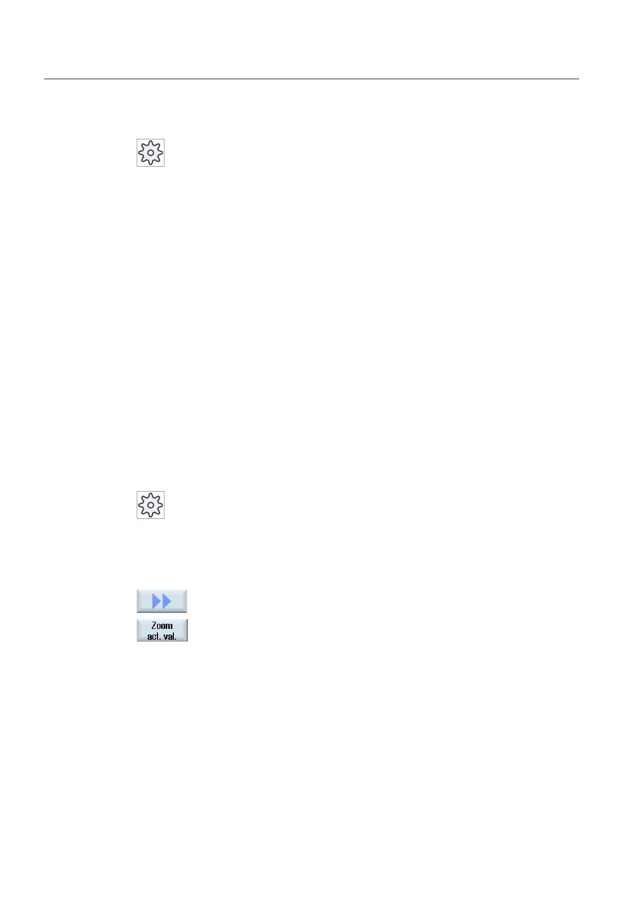
Press the ">>" and "Zoom act.val." softkeys.
Universal
32
Operating Manual, 03/2013, 6FC5398-6AP40-3BA1
Introduction
1.4 Operator interface
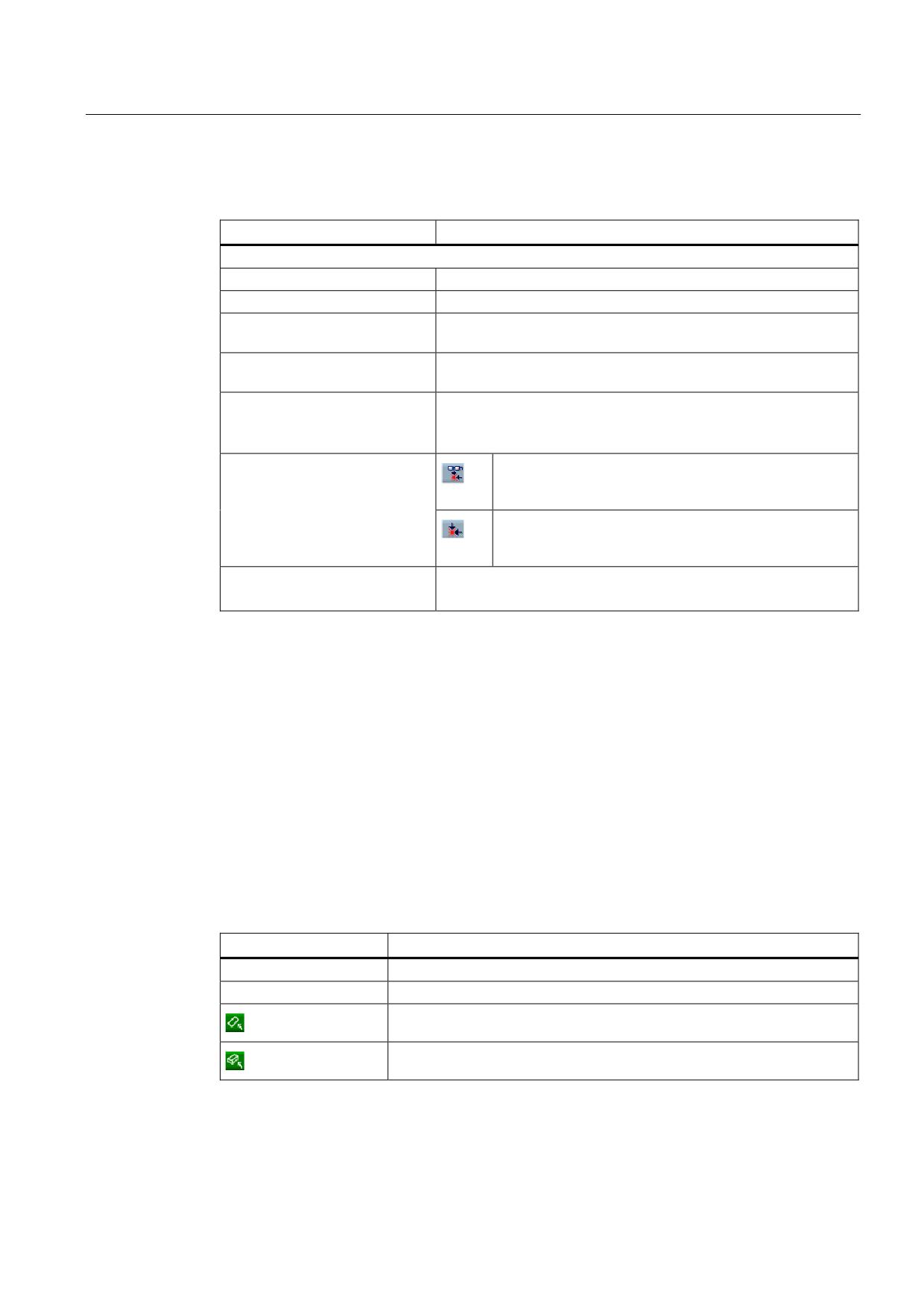
Overview of display
Display
Meaning
Header columns
Work/Machine
Display of axes in selected coordinate system.
Position
Position of displayed axes.
Display of distance-to-go
The distance-to-go for the current NC block is displayed while the
program is running.
Feed/override
The feed acting on the axes, as well as the override, are displayed
in the full-screen version.
Repos offset
The distances traversed in manual mode are displayed.
This information is only displayed when you are in the "Repos"
submode.
Collision monitoring
The collision avoidance is switched on for the JOG and
(only 840D sl)
MDI or AUTOMATIC modes and at least one active
collision pair is present.
The collision avoidance is switched off for the JOG and
MDI or AUTOMATIC modes or no active collision pair is
present.
Footer
Display of active work offsets and transformations.
The T, F, S values are also displayed in the full-screen version.
See also
Zero offsets (Page 63)
1.4.4
T,F,S window
The most important data concerning the current tool, the feedrate (path feed or axis feed in
JOG) and the spindle is displayed in the T, F, S window.
In addition to the "T, F, S" window name, the following information is also displayed:
Display
Meaning
BC (example)
Name of the tool carrier
Turning (example)
Name of the active kinematic transformation
Active tool carrier rotated in the plane
Active tool carrier swiveled in space
Universal
Operating Manual, 03/2013, 6FC5398-6AP40-3BA1
33
Introduction
1.4 Operator interface
Tool data
Display
Meaning
T
Tool name
Name of the current tool
Location
Location number of the current tool
D
Cutting edge of the current tool
The tool is displayed with the associated tool type symbol corresponding to
the actual coordinate system in the selected cutting edge position.
If the tool is swiveled, then this is taken into account in the display of the
cutting edge position.
In DIN-ISO mode the H number is displayed instead of the cutting edge
number.
H
H number (tool offset data record for DIN-ISO mode)
If there is a valid D number, this is also displayed.
Ø
Diameter of the current tool
R
Radius of the current tool
Z
Z value of the current tool
X
X value of the current tool
Feed data
Display
Meaning
F
Feed disable
Actual feed value
If several axes traverse, is displayed for:
• "JOG" mode: Axis feed for the traversing axis
• "MDA" and "AUTO" mode: Programmed axis feed
Rapid traverse
G0 is active
0.000
No feed is active
Override
Display as a percentage
Spindle data
Display
Meaning
S
S1
Spindle selection, identification with spindle number and main spindle
Speed
Actual value (when spindle turns, display increases)
Setpoint (always displayed, also during positioning)
Universal
34
Operating Manual, 03/2013, 6FC5398-6AP40-3BA1
Introduction
1.4 Operator interface
Display
Meaning
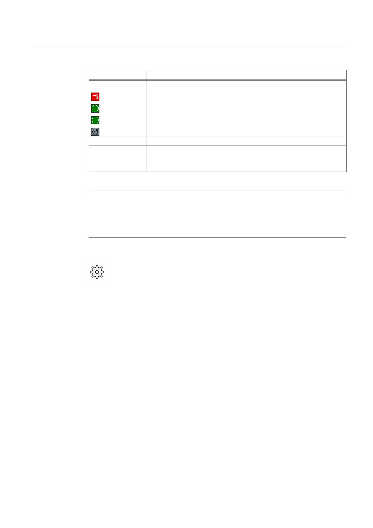
Symbol
Spindle status
Spindle not enabled
Spindle is turning clockwise
Spindle is turning counterclockwise
Spindle is stationary
Override
Display as a percentage
Spindle utilization
Display between 0 and 100%
rate
The upper limit value can be greater than 100%.
See machine manufacturer's specifications.
Note
Display of logical spindles
If the spindle converter is active, logical spindles are displayed in the workpiece coordinate
system. When switching over to the machine coordinate system, the physical spindles are
displayed.
Machine manufacturer
Please refer to the machine manufacturer's specifications.
1.4.5
Current block display
The window of the current block display shows you the program blocks currently being
executed.
Display of current program
The following information is displayed in the running program:
● The workpiece name or program name is entered in the title row.
● The program block which is just being processed appears colored.
Universal
Operating Manual, 03/2013, 6FC5398-6AP40-3BA1
35

Introduction
1.4 Operator interface
Editing a program directly
In the Reset state, you can edit the current program directly.
1.
Press the <INSERT> key.
2.
Place the cursor at the relevant position and edit the program block.
Direct editing is only possible for G code blocks in the NC memory, not
for external execution.
3.
Press the <INSERT> key to exit the program and the edit mode again.
See also
Correcting a program (Page 98)
1.4.6
Operation via softkeys and buttons
Operating areas/operating modes
The user interface consists of different windows featuring eight horizontal and eight vertical
softkeys.
You operate the softkeys with the keys next to the softkey bars.
You can display a new window or execute functions using the softkeys.
The operating software is sub-divided into six operating areas (machine, parameter,
program, program manager, diagnosis, startup) and five operating modes or submodes
(JOG, MDA, AUTO, TEACH IN, REF POINT, REPOS).
Changing the operating area
Press the <MENU SELECT> key and select the desired operating area using
the horizontal softkey bar.
You can call the "Machine" operating area directly using the key on the operator panel.
Press the <MACHINE> key to select the "machine" operating area.
Universal
36
Operating Manual, 03/2013, 6FC5398-6AP40-3BA1
Introduction
1.4 Operator interface
Changing the operating mode
You can select a mode or submode directly using the keys on the machine control panel or
using the vertical softkeys in the main menu.
General keys and softkeys
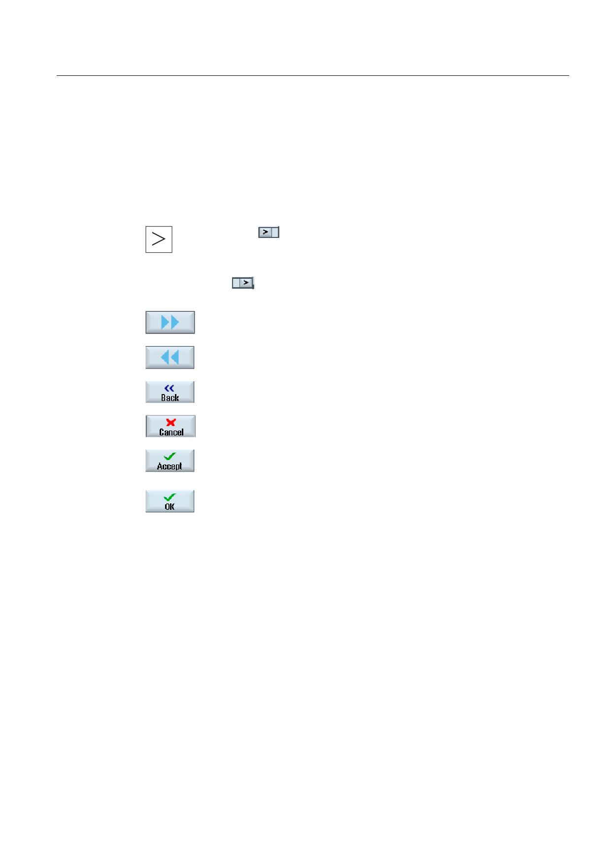
When the
symbol appears to the right of the dialog line on the user
interface, you can change the horizontal softkey bar within an operating area.
To do so, press the menu forward key.
The
symbol indicates that you are in the expanded softkey bar.
Pressing the key again will take you back to the original horizontal softkey bar.
Use the ">>" softkey to open a new vertical softkey bar.
Use the "<<" softkey to return to the previous vertical softkey bar.
Use the "Return" softkey to close an open window.
Use the "Cancel" softkey to exit a window without accepting the entered
values and return to the next highest window.
When you have entered all the necessary parameters in the parameter screen
form correctly, you can close the window and save the parameters using the
"Accept" softkey. The values you entered are applied to a program.
Use the "OK" softkey to initiate an action immediately, e.g. to rename or
delete a program.
See also
Controls on the machine control panel (Page 25)
Channel switchover (Page 57)
Universal
Operating Manual, 03/2013, 6FC5398-6AP40-3BA1
37
Introduction
1.4 Operator interface
1.4.7
Entering or selecting parameters
When setting up the machine and during programming, you must enter various parameter
values in the entry fields. The backg0round color of the fields provides information on the
status of the entry field.
Orange backg0round
The input field is selected
Light orange backg0round
The input field is in edit mode
Pink backg0round
The entered value is incorrect
Selecting parameters
Some parameters require you to select from a number of options in the input field. Fields of
this type do not allow you to type in a value.
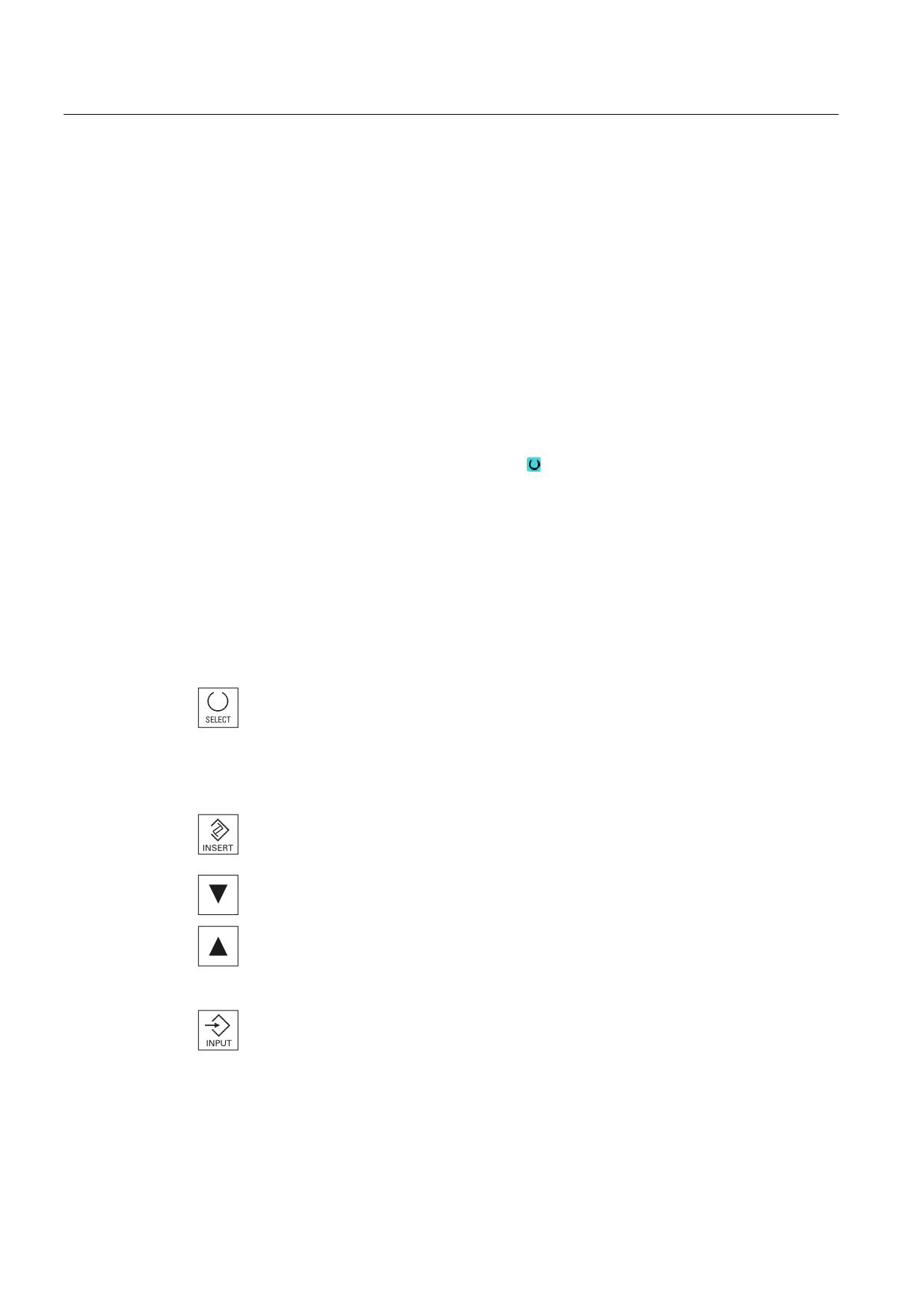
The selection symbol is displayed in the tooltip:
Associated selection fields
There are selection fields for various parameters:
● Selection of units
● Changeover between absolute and incremental dimensions
Procedure
1.
Keep pressing the <SELECT> key until the required setting or unit is
selected.
The <SELECT> key only works if there are several selection options
available.
- OR -
Press the <INSERT> key.
The selection options are displayed in a list.
2.
Select the required setting using the <Cursor down> and <Cursor up>
keys.
3.
If required, enter a value in the associated input field.
4.
Press the <INPUT> key to complete the parameter input.
Universal
38
Operating Manual, 03/2013, 6FC5398-6AP40-3BA1
Introduction
1.4 Operator interface
Changing or calculating parameters
If you only want to change individual characters in an input field rather than overwriting the
entire entry, switch to insertion mode.
In this mode, you can also enter simple calculation expressions, without having to explicitly
call the calculator. You can execute the four basic calculation types, work with expressions in
brackets as well as generate square roots and squares.
Note
Generating square roots and squares
The extract roots and generate square functions is not available in the parameter screens of
the cycles and functions in the "Program" operating area.
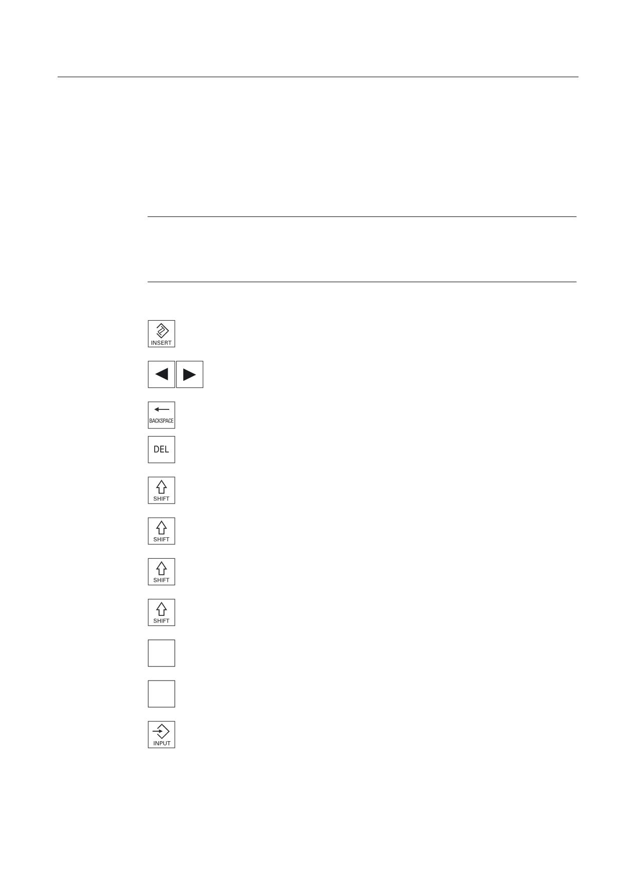
Press the <INSERT> key.
The insert mode is activated.
You can navigate within the input field using the <Cursor left> and
<Cursor right> keys.
Use the <BACKSPACE> and <DEL> key to delete individual characters.
+ <*>
Enter the multiplication characters using the <SHIFT> + <*> keys.
+ </>
Enter the division character using the <SHIFT> + </> keys.
Enter bracket expressions using the <SHIFT> + <(> and <SHIFT> + <)>
keys.
+ <)>
+ <number> Enter "r" or "R" as well as the number x from which you would like to
5
extract the root.
+ <number> Enter "s" or "S" as well as the number x for which you would like to
6
generate the square.
Close the value entry using the <INPUT> key and the result is
transferred into the field.
Universal
Operating Manual, 03/2013, 6FC5398-6AP40-3BA1
39
Introduction
1.4 Operator interface
Accepting parameters
When you have correctly entered all necessary parameters, you can close the window and
save your settings.
You cannot accept the parameters if they are incomplete or obviously erroneous. In this
case, you can see from the dialog line which parameters are missing or were entered
incorrectly.
Press the "OK" softkey.
- OR -
Press the "Accept" softkey.
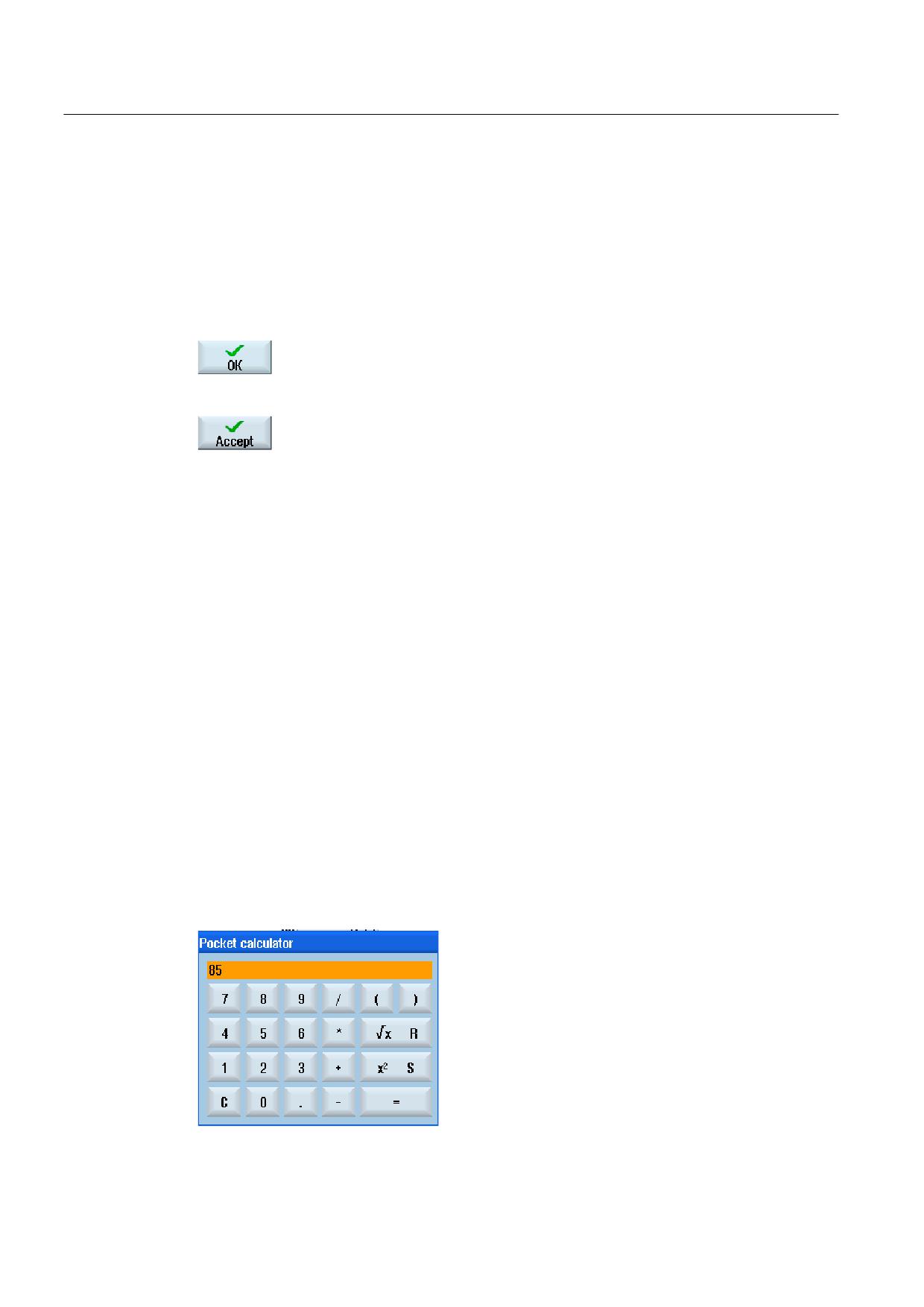
1.4.8
Pocket calculator
You can use the calculator to quickly calculate parameter values during programming. If, for
example, the diameter of a workpiece is only dimensioned indirectly in the workpiece
drawing, i.e., the diameter must be derived from the sum of several other dimension
specifications, you can calculate the diameter directly in the input field of this parameter.
Calculation methods
The following arithmetic operations are available:
● Addition
● Subtraction
● Multiplication
● Division
● Calculation with parentheses
● Square root of x
● x squared
You can input a maximum of 256 characters in a field.
Universal
40
Operating Manual, 03/2013, 6FC5398-6AP40-3BA1
Introduction
1.4 Operator interface
Procedure
1.
Position the cursor on the desired entry field.
2.
Press the <=> key.
The calculator is displayed.
3.
Input the arithmetic statement.
You can use arithmetic symbols, numbers, and commas.
4.
Press the equals symbol on the calculator.
- OR -
Press the "Calculate" softkey.
- OR -
Press the <INPUT> key.
The new value is calculated and displayed in the entry field of the
calculator.
5.
Press the "Accept" softkey.
The calculated value is accepted and displayed in the entry field of the
window.
Note
Input order for functions
When using the square root or squaring functions, make sure to press the "R" or "S" function
keys, respectively, before entering a number.
See also
Entering or selecting parameters (Page 38)
Universal
Operating Manual, 03/2013, 6FC5398-6AP40-3BA1
41
Introduction
1.4 Operator interface
1.4.9
Context menu
When you right-click, the context menu opens and provides the following functions:
● Cut
Cut Ctrl+X
● Copy
Copy Ctrl+C
● Paste
Paste Ctrl+V
Program editor
Additional functions are available in the editor
● Undo the last change
Undo Ctrl+Z
● Redo the changes that were undone
Redo Ctrl+Y
Up to 10 changes can be undone.
1.4.10
Touch operation
If you have an operator panel with a touch screen, you can perform the following functions
with touch operation:
Operating area switchover
You can display the operating area menu by touching the display symbol for
the active operating area in the status display.
Channel switchover
You can switch over to the next channel by touching the channel display
in the status display.
Universal
42
Operating Manual, 03/2013, 6FC5398-6AP40-3BA1
Introduction
1.4 Operator interface
1.4.11
Changing the user interface language
Procedure
1.
Select the "Start-up" operating area.
2.
Press the "Change language" softkey.
The "Language selection" window opens. The language set last is
selected.
3.
Position the cursor on the desired language.
4.
Press the "OK" softkey.
- OR -
Press the <INPUT> key.
The user interface changes to the selected language.
Note
Changing the language directly on the input screens
You can switch between the user interface languages available on the controller directly on
the user interface by pressing the key combination <CTRL + L>.
Universal
Operating Manual, 03/2013, 6FC5398-6AP40-3BA1
43
Introduction
1.4 Operator interface
1.4.12
Entering Asian characters
You have the possibility of entering Asian characters.
Note
Call the input editor with <Alt + S>
The input editor can only be called there where it is permissible to enter Asian characters.
You can select a character by using the Pinyin phonetic notation, which enables Chinese
characters to be expressed by combining Latin letters.
The editor is available for the following Asian languages:
● Simplified Chinese
● Traditional Chinese
● Korean
Note
You require a special keyboard to enter Korean characters.
Structure of editor
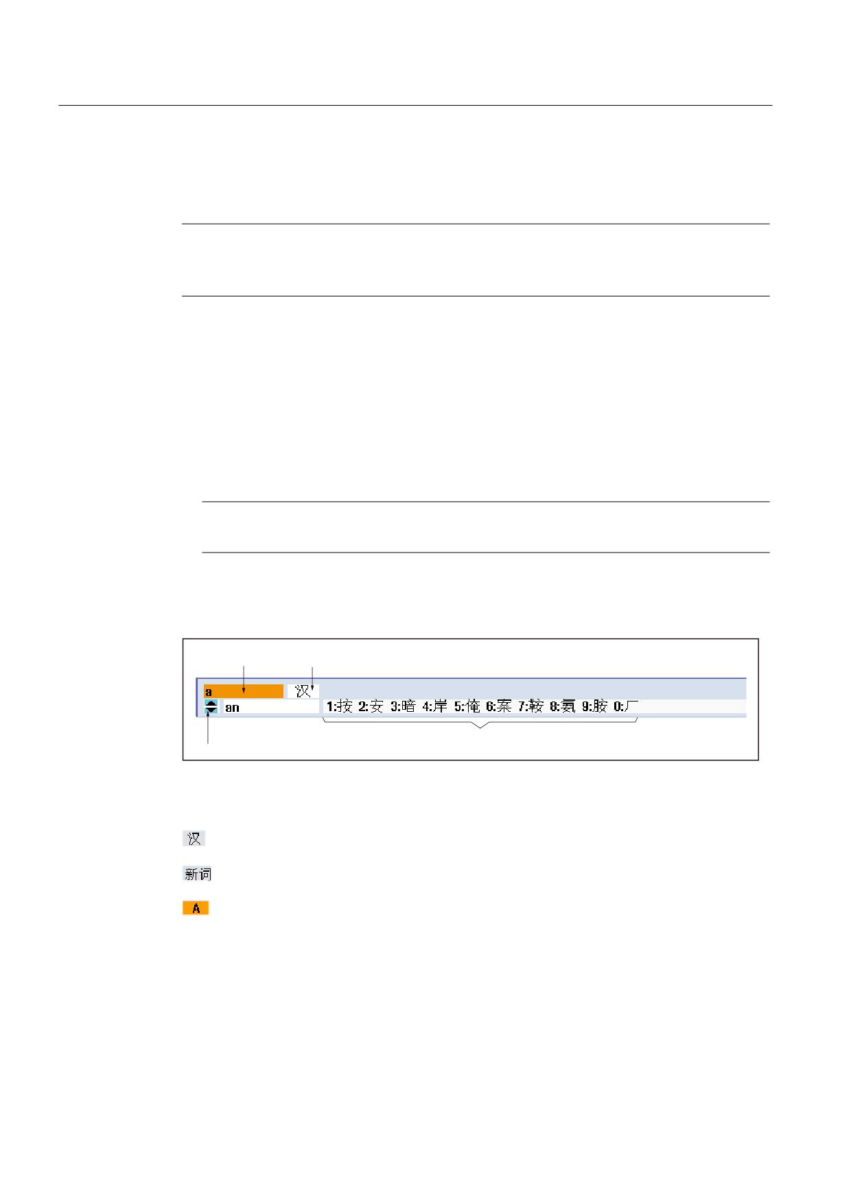
3KRQHWLF LQSXW
)XQFWLRQ VHOHFWLRQ
2IIHUHG FKDUDFWHUV
3KRQHWLF VHOHFWLRQ IURP GLFWLRQDU\
Functions
Pinyin input
Editing of the dictionary
Input of Latin letters
Precondition
The control has been set to Chinese or Korean.
Universal
44
Operating Manual, 03/2013, 6FC5398-6AP40-3BA1
Introduction
1.4 Operator interface
Procedure
Editing characters
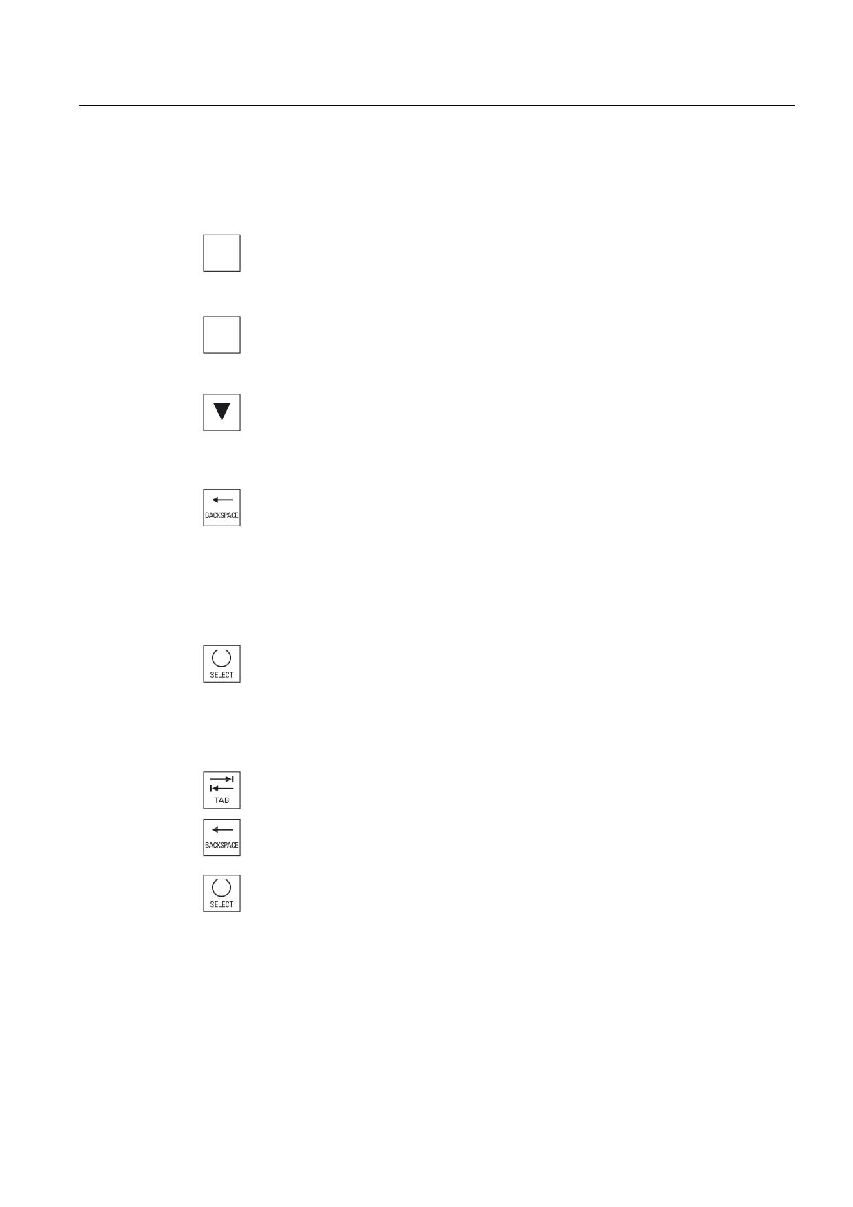
1.
Open the screen form and position the cursor on the entry field and
$
press the <Alt +S> keys.
The editor is displayed.
+
6
2.
Enter the desired phonetic notation.
3.
Click the <Cursor down> key to access the dictionary.
4.
By keeping the <Cursor down> key pressed, displays all the entered
phonetic notations and the associated selection characters.
5.
Press the <BACKSPACE> softkey to delete entered phonetic notations.
6.
Press the number key to insert the associated character.
When a character is selected, the editor records the frequency with
which it is selected for a specific phonetic notation and offers this
character at the top of the list when the editor is next opened.
Editing the dictionary
1.
Select the dictionary editing function in the selection box.
The editor provides a further line in which the combined characters and
phonetic notations are displayed.
2.
Enter the desired phonetic notation in the phonetic input field.
Various characters are displayed for this phonetic notation, from which
you can select a character by entering either of the appropriate number
(1 to 9).
You can toggle the input cursor between the compound phonetic
notations field and the phonetic input field by pressing the <TAB> key.
Combined characters are cancelled via the <BACKSPACE> key.
3.
Press the <SELECT> key to take a combined phonetic notation into the
dictionary.
Universal
Operating Manual, 03/2013, 6FC5398-6AP40-3BA1
45
Introduction
1.4 Operator interface
1.4.13
Protection levels
The input and modification of data in the control system is protected by passwords at
sensitive places.
Access protection via protection levels
The input or modification of data for the following functions depends on the protection level
setting:
● Tool offsets
● Zero offsets
● Setting data
● Program creation / program editing
Note
Configuring access levels for softkeys
You have the option of providing softkeys with protection levels or completely hiding
them.
References
For additional information, please refer to the following documentation:
Commissioning Manual SINUMERIK Operate (IM9) / SINUMERIK 840D sl
Softkeys
Machine operating area
Protection level
End user
(protection level 3)
Parameters operating area
Protection level
Tool management lists
Keyswitch 3
(protection level 4)
Universal
46
Operating Manual, 03/2013, 6FC5398-6AP40-3BA1
Introduction
1.4 Operator interface
Diagnostics operating area
Protection level
Keyswitch 3
(protection level 4)
User
(protection level 3)
User
(protection level 3)
Manufacturer
(protection level 1)
User
(protection level 3)
Service
(protection level 2)
Start-up operating area
Protection levels
End user
(protection level 3)
Keyswitch 3
(protection level 4)
Keyswitch 3
(protection level 4)
Keyswitch 3
(protection level 4)
Keyswitch 3
(protection level 4)
Service
(protection level 2)
End user
(protection level 3)
End user
(protection level 3)
Universal
Operating Manual, 03/2013, 6FC5398-6AP40-3BA1
47
Introduction
1.4 Operator interface
1.4.14
Online help in SINUMERIK Operate
A comprehensive context-sensitive online help is stored in the control system.
● A brief description is provided for each window and, if required, step-by-step instructions
for the operating sequences.
● A detailed help is provided in the editor for every entered G code. You can also display all
G functions and take over a selected command directly from the help into the editor.
● A help page with all parameters is provided on the input screen in the cycle programming.
● Lists of the machine data
● Lists of the setting data
● Lists of the drive parameters
● List of all alarms
Procedure
Calling context-sensitive online help
1.
You are in an arbitrary window of an operating area.
2.
Press the <HELP> key or on an MF2 keyboard, the <F12> key.
The help page of the currently selected window is opened in a
subscreen.
3.
Press the "Full screen" softkey to use the entire user interface for the
display of the online help.
Press the "Full screen" softkey again to return to the subscreen.
4.
If further helps are offered for the function or associated topics, position
the cursor on the desired link and press the "Follow reference" softkey.
The selected help page is displayed.
5.
Press the "Back to reference" softkey to jump back to the previous help.
Calling a topic in the table of contents
1.
Press the "Table of contents" softkey.
Depending on which technology you are using, the Operating Manuals
"Operator control Milling", "Operator control Turning" or "Operator
control Universal" as well as the "Programming" Programming Manual
are displayed.
Universal
48
Operating Manual, 03/2013, 6FC5398-6AP40-3BA1
Introduction
1.4 Operator interface
2.
Select the desired manual with the <Cursor down> and <Cursor up>
keys.
3
Press the <Cursor right> or <INPUT> key or double-click to open the
manual and the section.
4.
Navigate to the desired topic with the "Cursor down" key.
5.
Press the <Follow reference> softkey or the <INPUT> key to display the
help page for the selected topic.
6.
Press the "Current topic" softkey to return to the original help.
Searching for a topic
1.
Press the "Search" softkey.
The "Search in Help for:" window is opened.
2.
Activate the "Full text " checkbox to search in all help pages.
If the checkbox is not activated, a search is performed in the table of
contents and in the index.
3.
Enter the desired keyword in the "Text" field and press the "OK" softkey.
If you enter the search term on the operator panel, replace an umlaut
(accented character) by an asterisk (*) as dummy.
All entered terms and sentences are sought with an AND operation. In
this way, only documents and entries that satisfy all the search criteria
are displayed.
4.
Press the "Keyword index" softkey if you only want to display the index
of the operating and programming manual.
Universal
Operating Manual, 03/2013, 6FC5398-6AP40-3BA1
49
Introduction
1.4 Operator interface
Displaying alarm descriptions and machine data
1.
If messages or alarms are pending in the "Alarms", "Messages" or
"Alarm Log" window, position the cursor at the appropriate display and
press the <HELP> or the <F12> key.
The associated alarm description is displayed.
2.
If you are in the "Start-up" operating area in the windows for the display
of the machine, setting and drive data, position the cursor on the
desired machine data or drive parameter and press the <HELP> or the
<F12> key.
The associated data description is displayed.
Displaying and inserting a G code command in the editor
1.
A program is opened in the editor.
Position the cursor on the desired G code command and press the
<HELP> or the <F12> key.
The associated G code description is displayed.
2.
Press the "Display all G functions" softkey.
3.
With the aid of the search function, select, for example, the desired G
code command.
4.
Press the "Transfer to editor" softkey.
The selected G function is taken into the program at the cursor position.
5.
Press the "Exit help" softkey again to close the help.
Universal
50
Operating Manual, 03/2013, 6FC5398-6AP40-3BA1
Setting up the machine
2
2.1
Switching on and switching off
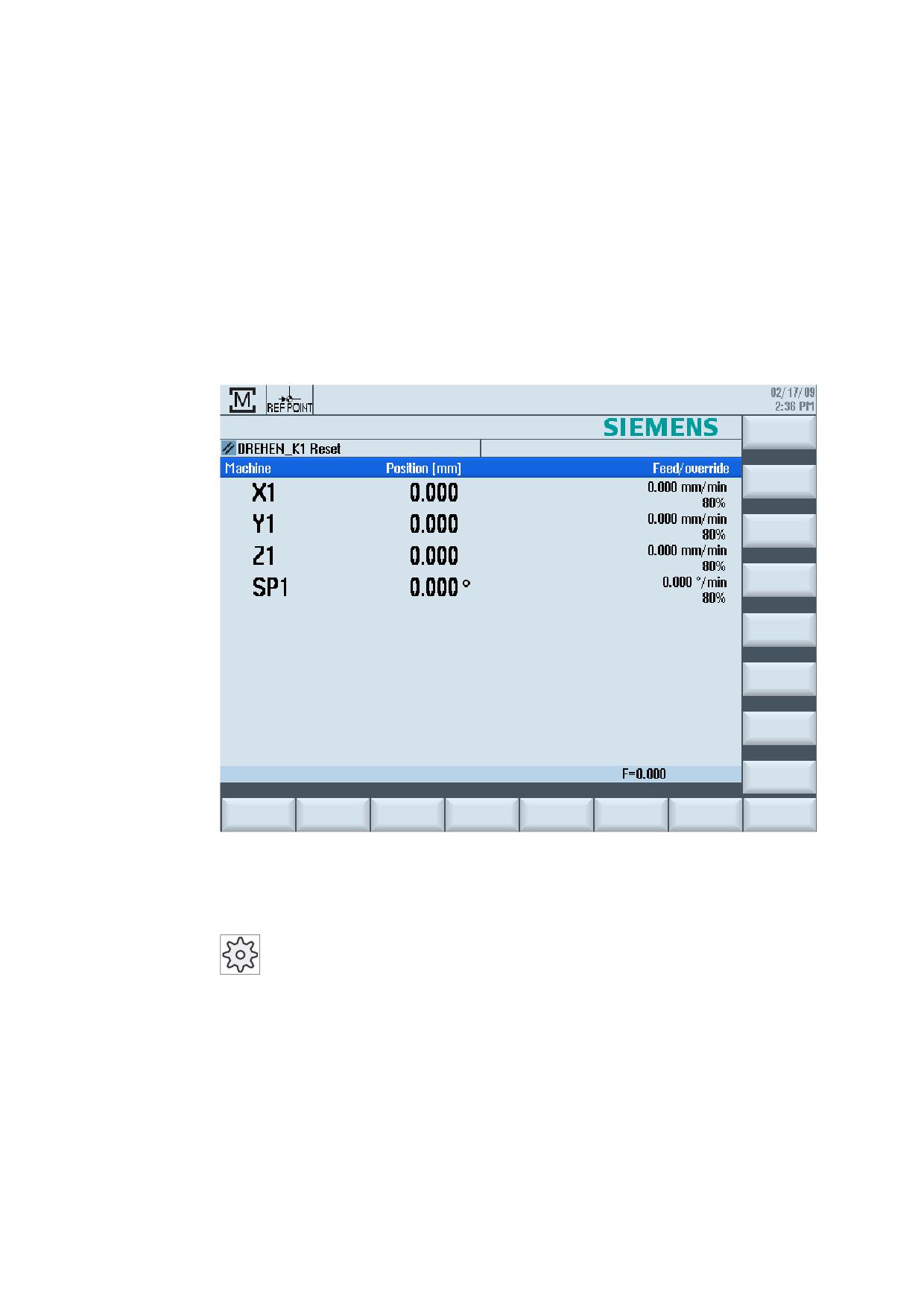
Start-up
When the control starts up, the main screen opens according to the operating mode
specified by the machine manufacturer. In general, this is the main screen for the "REF
POINT" submode.
Machine manufacturer
Please also refer to the machine manufacturer's instructions.
Universal
Operating Manual, 03/2013, 6FC5398-6AP40-3BA1
51
Setting up the machine
2.2 Approaching a reference point
2.2
Approaching a reference point
2.2.1
Referencing axes
Your machine tool can be equipped with an absolute or incremental path measuring system.
An axis with incremental path measuring system must be referenced after the controller has
been switched on - however, an absolute path measuring system does not have to be
referenced.
For the incremental path measuring system, all the machine axes must therefore first
approach a reference point, the coordinates of which are known to be relative to the machine
zero-point.
Sequence
Prior to the approach, the axes must be in a position from where they can approach the
reference point without a collision.
The axes can also all approach the reference point simultaneously, depending on the
manufacturer’s settings.
Machine manufacturer
Please refer to the machine manufacturer's specifications.
NOTICE
Risk of collision
If the axes are not in a collision-free position, you must first traverse them to safe positions
in "JOG" or "MDI" mode.
You must follow the axis motions directly on the machine!
Ignore the actual value display until the axes have been referenced!
The software limit switches are not active!
Procedure
1.
Press the <JOG> key.
2.
Press the <REF. POINT> key.
Universal
52
Operating Manual, 03/2013, 6FC5398-6AP40-3BA1

Setting up the machine
2.2 Approaching a reference point
3.
Select the axis to be traversed.
;
=
4.
Press the <-> or <+> key.
The selected axis moves to the reference point.
If you have pressed the wrong direction key, the action is not accepted
and the axes do not move.
A symbol is shown next to the axis if it has been referenced.
The axis is referenced as soon as the reference point is reached. The actual value display is
set to the reference point value.
From now on, path limits, such as software limit switches, are active.
End the function via the machine control panel by selecting operating mode "AUTO" or
"JOG".
2.2.2
User agreement
If you are using Safety Integrated (SI) on your machine, you will need to confirm that the
current displayed position of an axis corresponds to its actual position on the machine when
you reference an axis. Your confirmation is the requirement for the availability of other Safety
Integrated functions.
You can only give your user agreement for an axis after it has approached the reference
point.
The displayed axis position always refers to the machine coordinate system (Machine).
Option
User agreement with Safety Integrated is only possible with a software option.
Procedure
1.
Select the "Machine" operating area.
2.
Press the <REF POINT> key.
Universal
Operating Manual, 03/2013, 6FC5398-6AP40-3BA1
53
Setting up the machine
2.2 Approaching a reference point
3.
Select the axis to be traversed.
;
=
4.
Press the <-> or <+> key.
The selected axis moves to the reference point and stops. The
coordinate of the reference point is displayed.
The axis is marked with
5.
Press the "User enable" softkey.
The "User Agreement" window opens.
It shows a list of all machine axes with their current position and SI
position.
5.
Position the cursor in the "Acknowledgement" field for the axis in
question.
6.
Activate the acknowledgement with the <SELECT> key.
The selected axis is marked with an "x" meaning "safely referenced"
in the "Acknowledgement" column.
By pressing the <SELECT> key again, you deactivate the
acknowledgement again.
Universal
54
Operating Manual, 03/2013, 6FC5398-6AP40-3BA1
Setting up the machine
2.3 Modes of operation
2.3
Modes of operation
2.3.1
General information
You can work in three different operating modes.
"JOG" mode
"JOG" mode is used for the following preparatory actions:
● Approach reference point, i.e. the machine axis is referenced
● Preparing a machine for executing a program in automatic mode, i.e. measuring tools,
measuring the workpiece and, if necessary, defining the work offsets used in the program
● Traversing axes, e.g. during a program interruption
● Positioning axes
Select "JOG"
Press the <JOG> key.
"REF POINT" operating mode
The "REF POINT" operating mode is used to synchronize the control and the machine. For
this purpose, you approach the reference point in "JOG" mode.
Selecting "REF POINT"
Press the <REF POINT> key.
"REPOS" operating mode
The "REPOS" operating mode is used for repositioning to a defined position. After a program
interruption (e.g. to correct tool wear values) move the tool away from the contour in "JOG"
mode.
The distances traversed in "JOG" mode are displayed in the actual value window as the
"Repos" offset.
"REPOS" offsets can be displayed in the machine coordinate system (MCS) or workpiece
coordinate system (WCS).
Universal
Operating Manual, 03/2013, 6FC5398-6AP40-3BA1
55
Setting up the machine
2.3 Modes of operation
Selecting "Repos"
Press the <REPOS> key.
"MDI" mode (Manual Data Input)
In "MDI" mode, you can enter and execute G code commands non-modally to set up the
machine or to perform a single action.
Selecting "MDI"
Press the <MDI> key.
"AUTO" mode
In automatic mode, you can execute a program completely or only partially.
Select "AUTO"
Press the <AUTO> key.
"TEACH IN" operating mode
"TEACH IN" is available in the "AUTO" and "MDI" operating modes.
There you may create, edit and execute part programs (main programs or subroutines) for
motional sequences or simple workpieces by approaching and saving positions.
Selecting "Teach In"
Press the <TEACH IN> key.
Universal
56
Operating Manual, 03/2013, 6FC5398-6AP40-3BA1
Setting up the machine
2.3 Modes of operation
2.3.2
Modes groups and channels
Every channel behaves like an independent NC. A maximum of one part program can be
processed per channel.
● Control with 1channel
One mode group exists.
● Control with several channels
Channels can be grouped to form several "mode groups."
Example
Control with 4 channels, where machining is carried out in 2 channels and 2 other channels
are used to control the transport of the new workpieces.
Mode group 1 channel 1 (machining)
Channel 2 (transport)
Mode group 2 channel 3 (machining)
Channel 4 (transport)
Mode groups (MGs)
Technologically-related channels can be combined to form a mode group.
Axes and spindles of the same mode group can be controlled by one or more channels.
An operating mode group is in one of "Automatic", "JOG" or "MDI" operating modes, i.e.,
several channels of an operating mode group can never assume different operating modes.
2.3.3
Channel switchover
It is possible to switch between channels when several are in use. Since individual channels
may be assigned to different mode groups, a channel switchover command is also an implicit
mode switchover command.
When a channel menu is available, all of the channels are displayed on softkeys and can be
switched over.
Universal
Operating Manual, 03/2013, 6FC5398-6AP40-3BA1
57
Setting up the machine
2.3 Modes of operation
Changing the channel
Press the <CHANNEL> key.
The channel changes over to the next channel.
- OR -
If the channel menu is available, a softkey bar is displayed. The active
channel is highlighted.
Another channel can be selected by pressing one of the other softkeys.
References
Commissioning Manual SINUMERIK Operate (IM9) / SINUMERIK 840D sl
Channel switchover via touch operation
On the HT 8 and when using a touch screen operator panel, you can switch to the next
channel or display the channel menu via touch operation in the status display.
See also
HT 8 overview (Page 285)
Universal
58
Operating Manual, 03/2013, 6FC5398-6AP40-3BA1
Setting up the machine
2.4 Settings for the machine
2.4
Settings for the machine
2.4.1
Switching over the coordinate system (MCS/WCS)
The coordinates in the actual value display are relative to either the machine coordinate
system or the workpiece coordinate system.
By default, the workpiece coordinate system is set as a reference for the actual value
display.
The machine coordinate system (MCS), in contrast to the workpiece coordinate system
(WCS), does not take into account any zero offsets, tool offsets and coordinate rotation.
Procedure
1.
Select the "Machine" operating area.
2.
Press the <JOG> or <AUTO> key.
3.
Press the "Act.vls. MCS" softkey.
The machine coordinate system is selected.
The title of the actual value window changes in the MCS.
Machine manufacturer
The softkey to changeover the coordinate system can be hidden. Please refer to the
machine manufacturer's specifications.
Universal
Operating Manual, 03/2013, 6FC5398-6AP40-3BA1
59
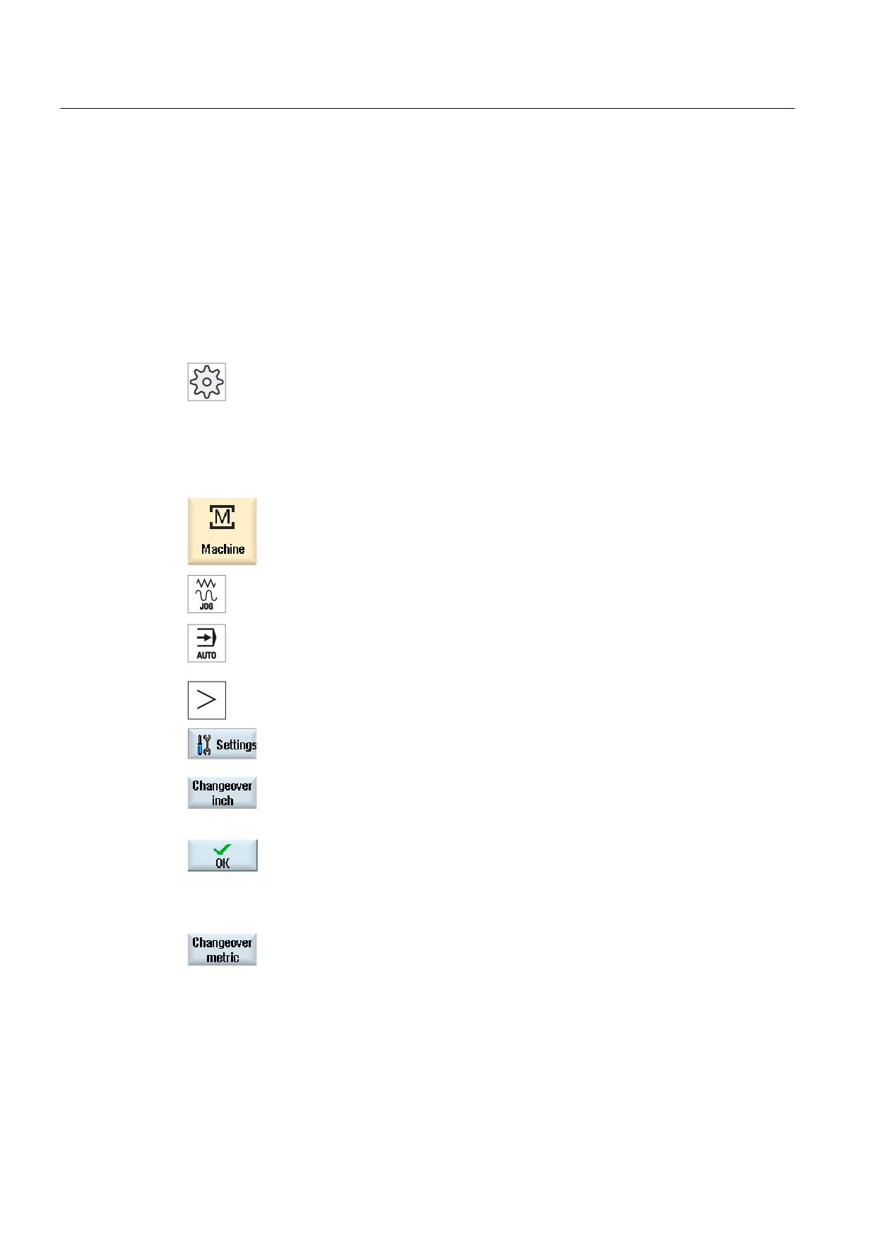
Setting up the machine
2.4 Settings for the machine
2.4.2
Switching the unit of measurement
You can set millimeters or inches as the unit of measurement. Switching the unit of
measurement always applies to the entire machine. All required information is automatically
converted to the new unit of measurement, for example:
● Positions
● Tool offsets
● Work offsets
Machine manufacturer
Please also refer to the machine manufacturer's instructions.
Proceed as follows
1.
Select <JOG> or <AUTO> mode in the "Machine" operating area.
2.
Press the menu forward key and the "Settings" softkey.
A new vertical softkey bar appears.
3.
Press the "Switch to inch" softkey.
A prompt asks you whether you really want to switch over the unit of
measurement.
4.
Press the "OK" softkey.
The softkey label changes to "Switch to metric".
The unit of measurement applies to the entire machine.
5.
Press the "Switch to metric" softkey to set the unit of measurement of
the machine to metric again.
Universal
60
Operating Manual, 03/2013, 6FC5398-6AP40-3BA1
Setting up the machine
2.4 Settings for the machine
2.4.3
Setting the zero offset
You can enter a new position value in the actual value display for individual axes when a
settable zero offset is active.
The difference between the position value in the machine coordinate system MCS and the
new position value in the workpiece coordinate system WCS is saved permanently in the
currently active zero offset (e.g. G54).
Relative actual value
Further, you also have the possibility of entering position values in the relative coordinate
system.
Note
The new actual value is only displayed. The relative actual value has no effect on the axis
positions and the active zero offset.
Resetting the relative actual value
Press the "Delete REL" softkey.
The actual values are deleted.
The softkeys to set the zero point in the relative coordinate system are only available if the
corresponding machine data is set.
Machine manufacturer
Please refer to the machine manufacturer's specifications.
Precondition
The controller is in the workpiece coordinate system.
The actual value is set in the reset state.
Note
Setting the ZO in the Stop state
If you enter the new actual value in the Stop state, the changes made are only visible and
only take effect when the program is continued.
Universal
Operating Manual, 03/2013, 6FC5398-6AP40-3BA1
61
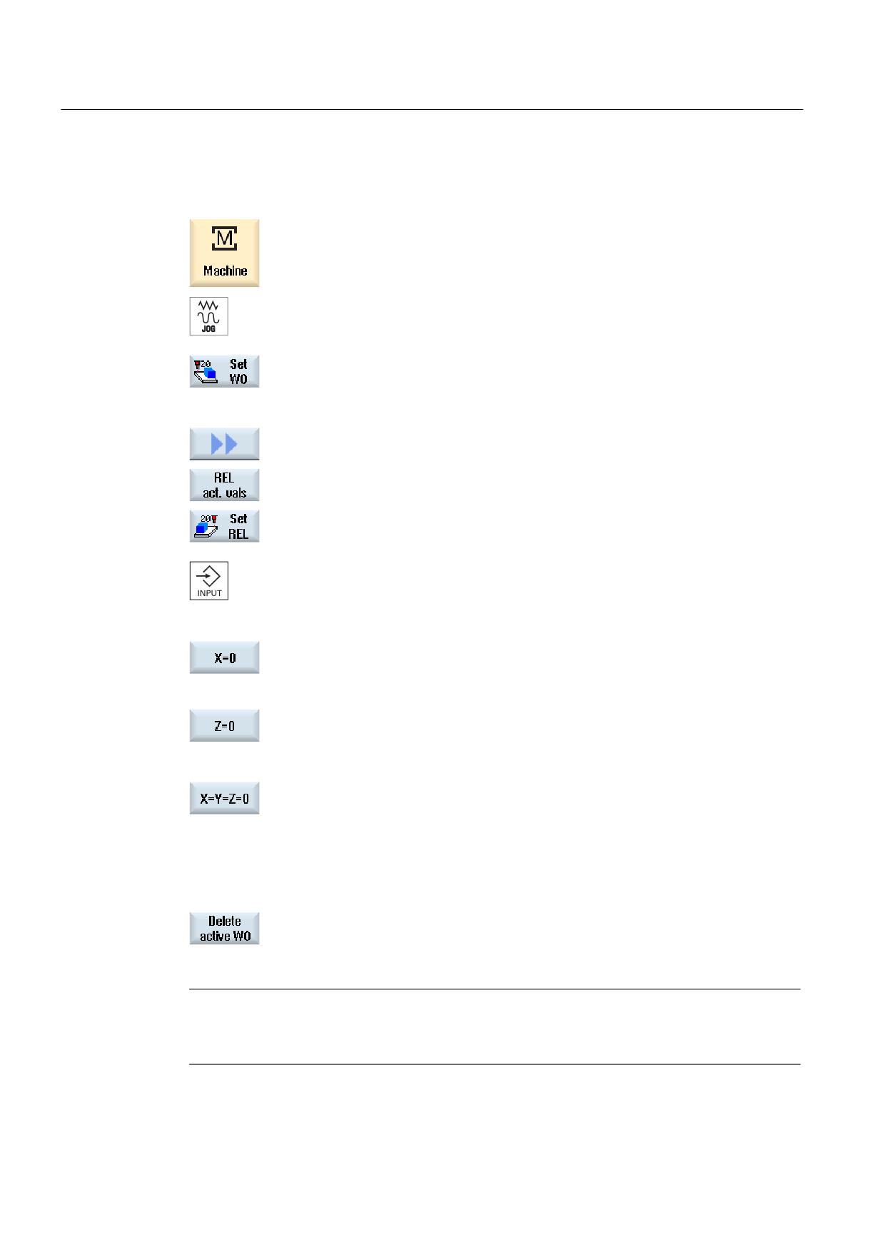
Setting up the machine
2.4 Settings for the machine
Procedure
1.
Select the "JOG" mode in the "Machine" operating area.
2.
Press the "Set ZO" softkey.
- OR -
Press the ">>", "REL act. vals" and "Set REL" softkeys to set position
values in the relative coordinate system.
3.
Enter the new required position value for X, Y or Z directly in the actual
value display (you can toggle between the axes with the cursor keys)
and press the "Input" key to confirm the entries.
- OR -
Press softkeys "X=0","Y=0" or "Z=0" to set the relevant position to zero.
- OR -
Press softkey "X=Y=Z=0" to set all axis positions to zero simultaneously.
Resetting the actual value
Press the "Delete active ZO" softkey.
The offset is deleted permanently.
Note
Irreversible active zero offset
The current active zero offset is irreversibly deleted by this action.
Universal
62
Operating Manual, 03/2013, 6FC5398-6AP40-3BA1
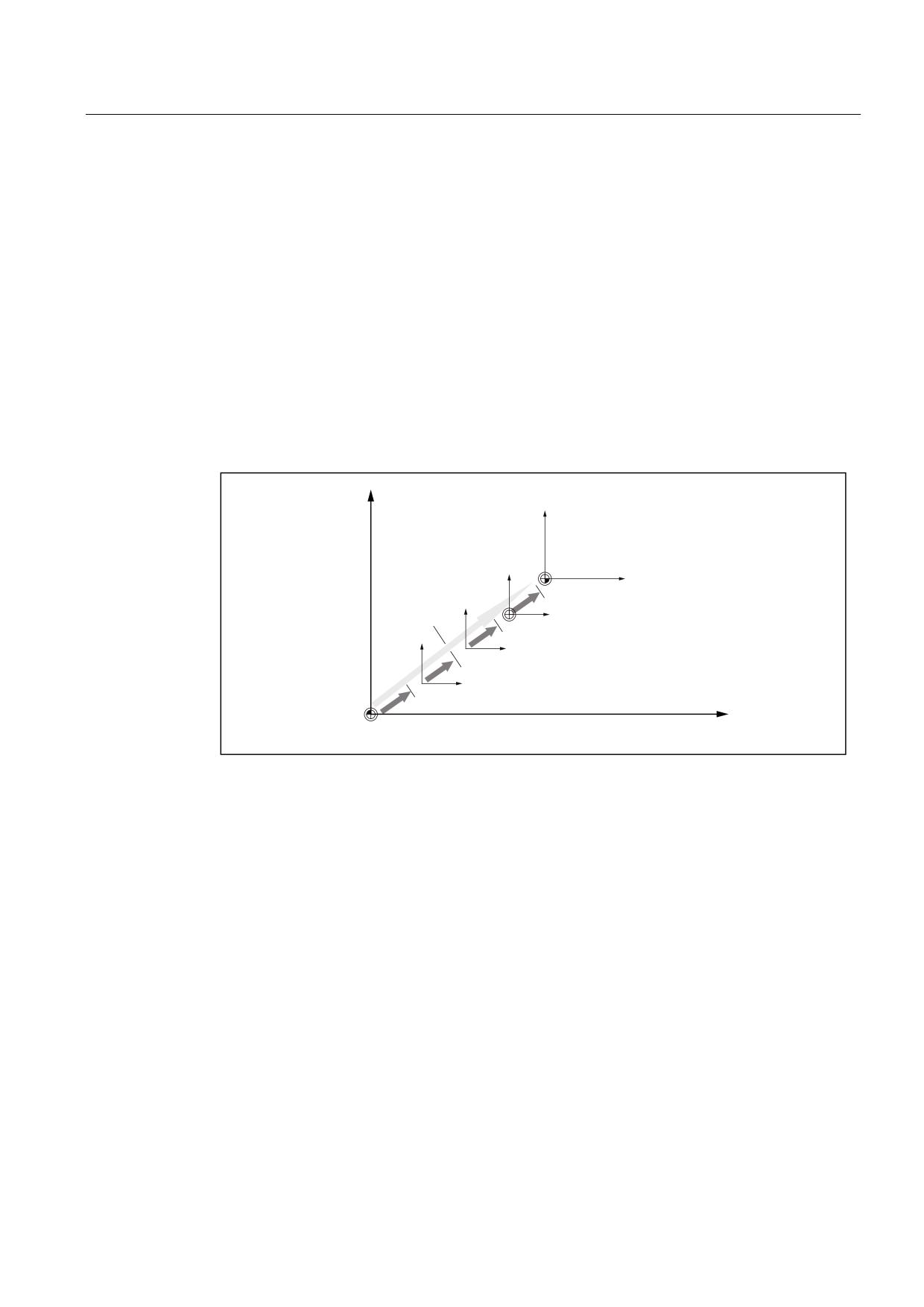
Setting up the machine
2.5 Zero offsets
2.5
Zero offsets
Following reference point approach, the actual value display for the axis coordinates is
based on the machine zero (M) of the machine coordinate system (Machine). The program
for machining the workpiece, however, is based on the workpiece zero (W) of the workpiece
coordinate system (Work). The machine zero and workpiece zero are not necessarily
identical. The distance between the machine zero and the workpiece zero depends on the
workpiece type and how it is clamped. This zero offset is taken into account during execution
of the program and can be a combination of different offsets.
Following reference point approach, the actual value display for the axis coordinates is
based on the machine zero of the machine coordinate system (Machine).
The actual value display of the positions can also refer to the SZS coordinate system
(settable zero system). The position of the active tool relative to the workpiece zero is
displayed.
:
:&6
&RRUGLQDWH WUDQVIRUPDWLRQ
7RWDO
6=6
RIIVHW
:RUN RIIVHW ILQH
:RUN RIIVHW FRDUVH
%DVLF RIIVHW
0&6
0
Figure 2-1
Zero offsets
When the machine zero is not identical to the workpiece zero, at least one offset (base offset
or zero offset) exists in which the position of the workpiece zero is saved.
Base offset
The base offset is a zero offset that is always active. If you have not defined a base offset, its
value will be zero. The base offset is specified in the "Zero Offset - Base" window.
Coarse and fine offsets
Every zero offset (G54 to G57, G505 to G599) consists of a coarse offset and a fine offset.
You can call the zero offsets from any program (coarse and fine offsets are added together).
Universal
Operating Manual, 03/2013, 6FC5398-6AP40-3BA1
63
Setting up the machine
2.5 Zero offsets
You can save the workpiece zero, for example, in the coarse offset, and then store the offset
that occurs when a new workpiece is clamped between the old and the new workpiece zero
in the fine offset.
Note
Deselect fine offset (only 840D sl)
You have the option of deselecting the fine offset using machine data MD18600
$MN_MM_FRAME_FINE_TRANS
2.5.1
Display active zero offset
The following zero offsets are displayed in the "Zero Offset - Active" window:
● Zero offsets, for which active offsets are included, or for which values are entered.
● Settable zero offsets
● Total zero offset
This window is generally used only for monitoring.
The availability of the offsets depends on the setting.
Machine manufacturer
Please refer to the machine manufacturer's specifications.
Procedure
1.
Select the "Parameter" operating area.
2.
Press the "Zero offset" softkey.
The "Zero Offset - Active" window is opened.
Universal
64
Operating Manual, 03/2013, 6FC5398-6AP40-3BA1
Setting up the machine
2.5 Zero offsets
Note
Further details on zero offsets
If you would like to see further details about the specified offsets or if you would like to
change values for the rotation, scaling or mirroring, press the "Details" softkey.
2.5.2
Displaying the zero offset "overview"
The active offsets or system offsets are displayed for all set-up axes in the "Zero Offset -
Overview" window.
In addition to the offset (course and fine), the rotation, scaling and mirroring defined using
this are also displayed.
This window is generally used only for monitoring.
Display of active zero offsets
Zero offsets
DRF
Displays the handwheel axis offset.
Basic reference
Displays the additional zero offsets programmed with $P_SETFRAME.
Access to the system offsets is protected via a keyswitch.
External ZO frame
Displays the additional zero offsets programmed with $P_EXTFRAME.
Total base ZO
Displays all effective basis offsets.
G500
Displays the zero offsets activated with G54 - G599.
Under certain circumstances, you can change the data using "Set ZO",
i.e. you can correct a zero point that has been set.
Tool reference
Displays the additional zero offsets programmed with
$P_TOOLFRAME.
Workpiece reference
Displays the additional zero offsets programmed with $P_WPFRAME.
Programmed ZO
Displays the additional zero offsets programmed with $P_PFRAME.
Cycle reference
Displays the additional zero offsets programmed with $P_CYCFRAME.
Total ZO
Displays the active zero offset, resulting from the total of all zero
offsets.
Universal
Operating Manual, 03/2013, 6FC5398-6AP40-3BA1
65
Setting up the machine
2.5 Zero offsets
Procedure
1.
Select the "Parameter" operating area.
2
Press the "Zero offset" and "Overview" softkeys.
The "Zero Offsets - Overview" window opens.
2.5.3
Displaying and editing base zero offset
The defined channel-specific and global base offsets, divided into coarse and fine offsets,
are displayed for all set-up axes in the "Zero offset - Base" window.
Machine manufacturer
Please refer to the machine manufacturer's specifications.
Procedure
1.
Select the "Parameter" operating area.
2.
Press the "Zero offset" softkey.
3.
Press the "Base" softkey.
The "Zero Offset - Base" window is opened.
4.
You can edit the values directly in the table.
Note
Activate base offsets
The offsets specified here are immediately active.
Universal
66
Operating Manual, 03/2013, 6FC5398-6AP40-3BA1
Setting up the machine
2.5 Zero offsets
2.5.4
Displaying and editing settable zero offset
All settable offsets, divided into coarse and fine offsets, are displayed in the "Zero Offset -
G54..G599" window.
Rotation, scaling and mirroring are displayed.
Procedure
1.
Select the "Parameter" operating area.
2.
Press the "Zero offset" softkey.
3.
Press the "G54…G599" softkey.
The "Zero Offset - G54..G599" window is opened.
Note
The labeling of the softkeys for the settable zero offsets varies, i.e. the
settable zero offsets configured on the machine are displayed
(examples: G54…G57, G54…G505, G54…G599).
Please observe the machine manufacturer's specifications.
4.
You can edit the values directly in the table.
Note
Activate settable zero offsets
The settable zero offsets must first be selected in the program before they have an impact.
Universal
Operating Manual, 03/2013, 6FC5398-6AP40-3BA1
67
Setting up the machine
2.5 Zero offsets
2.5.5
Displaying and editing details of the zero offsets
For each zero offset, you can display and edit all data for all axes. You can also delete zero
offsets.
For every axis, values for the following data will be displayed:
● Coarse and fine offsets
● Rotation
● Scaling
● Mirroring
Machine manufacturer
Please refer to the machine manufacturer's specifications.
Note
Settings for rotation, scaling and mirroring are specified here and can only be changed here.
Procedure
1.
Select the "Parameter" operating area.
2.
Press the "Zero offset" softkey.
3.
Press the "Active", "Base" or "G54…G599" softkey.
The corresponding window appears.
4.
Place the cursor on the desired zero offset to view its details.
5.
Press the "Details" softkey.
A window opens, depending on the selected zero offset, e.g. "Zero
Offset - Details: G54 to G599".
6.
You can edit the values directly in the table.
- OR -
Press the "Clear offset" softkey to reset all entered values.
Universal
68
Operating Manual, 03/2013, 6FC5398-6AP40-3BA1
Setting up the machine
2.5 Zero offsets
Press the "ZO +" or "ZO -" softkey to select the next or previous offset,
respectively, within the selected area ("Active", "Base", "G54 to G599")
without first having to switch to the overview window.
If you have reached the end of the range (e.g. G599), you will switch
automatically to the beginning of the range (e.g. G54).
These value changes are available in the part program immediately or after "Reset".
Machine manufacturer
Please refer to the machine manufacturer's specifications.
Press the "Back" softkey to close the window.
2.5.6
Deleting a zero offset
You have the option of deleting zero offsets. This resets the entered values.
Procedure
1.
Select the "Parameter" operating area.
2.
Press the "Zero offset" softkey.
3.
Press the "Active", "Base" or "G54…G599" softkey.
4.
Press the "Details" softkey.
5.
Position the cursor on the zero offset you would like to delete.
6.
Press the "Clear offset" softkey.
Universal
Operating Manual, 03/2013, 6FC5398-6AP40-3BA1
69
Setting up the machine
2.6 Monitoring axis and spindle data
2.6
Monitoring axis and spindle data
2.6.1
Specify working area limitations
The "Working area limitation" function can be used to limit the range within which a tool can
traverse in all channel axes. These commands allow you to set up protection zones in the
working area which are out of bounds for tool movements.
In this way, you are able to restrict the traversing range of the axes in addition to the limit
switches.
Requirements
You can only make changes in "AUTO" mode when in the RESET condition. These changes
are then immediate.
You can make changes in "JOG" mode at any time. These changes, however, only become
active at the start of a new motion.
Procedure
1.
Select the "Parameter" operating area.
2.
Press the "Setting data" softkey.
The "Working Area Limitation" window appears.
3.
Place the cursor in the required field and enter the new values via the
numeric keyboard.
The upper or lower limit of the protection zone changes according to
your inputs.
4.
Click the "active" checkbox to activate the protection zone.
Note
You will find all of the setting data in the "Start-up" operating area under "Machine data" via
the menu forward key.
Universal
70
Operating Manual, 03/2013, 6FC5398-6AP40-3BA1
Setting up the machine
2.6 Monitoring axis and spindle data
2.6.2
Editing spindle data
The speed limits set for the spindles that must not be under- or overshot are displayed in the
"Spindles" window.
You can limit the spindle speeds in fields "Minimum" and "Maximum" within the limit values
defined in the relevant machine data.
Spindle speed limitation at constant cutting rate
In field "Spindle speed limitation at G96", the programmed spindle speed limitation at
constant cutting speed is displayed together with the permanently active limitations.
This speed limitation, for example, prevents the spindle from accelerating to the max. spindle
speed of the current gear stage (G96) when performing tapping operations or machining
very small diameters.
Note
The "Spindle data" softkey only appears if a spindle is configured.
Procedure
1.
Select the "Parameter" operating area.
2.
Press the "Setting data" and "Spindle data" softkeys.
The "Spindles" window opens.
3.
If you want to change the spindle speed, place the cursor on the
"Maximum", "Minimum", or "Spindle speed limitation at G96" and enter a
new value.
Universal
Operating Manual, 03/2013, 6FC5398-6AP40-3BA1
71
Setting up the machine
2.7 Displaying setting data lists
2.7
Displaying setting data lists
You can display lists with configured setting data.
Machine manufacturer
Please refer to the machine manufacturer's specifications.
Procedure
1.
Select the "Parameter" operating area.
2.
Press the "Setting data" and "Data lists" softkeys.
The "Setting Data Lists" window opens.
3.
Press the "Select data list" softkey and in the "View" list, select the
required list with setting data.
2.8
Handwheel assignment
You can traverse the axes in the machine coordinate system (Machine) or in the workpiece
coordinate system (Work) via the handwheel.
Software option
You require the "Extended operator functions" option for the handwheel offset
(only for 828D).
All axes are provided in the following order for handwheel assignment:
● Geometry axes
When traversing, the geometry axes taken into account the actual machine status (e.g.
rotations, transformations). All channel machine axes, which are currently assigned to the
geometry axis, are in this case simultaneously traversed.
● Channel machine axes
Channel machine axes are assigned to the particular channel. They can only be
individually traversed, i.e. the actual machine state has no influence.
The also applies to channel machine axes, that are declared as geometry axes.
Universal
72
Operating Manual, 03/2013, 6FC5398-6AP40-3BA1
Setting up the machine
2.8 Handwheel assignment
Machine manufacturer
Please refer to the machine manufacturer's specifications.
Procedure
1.
Select the "Machine" operating area.
Press the <JOG>, <AUTO> or <MDI> key.
2.
Press the menu forward key and the "Handwheel" softkey.
The "Handwheel" window appears.
A field for axis assignment will be offered for every connected
handwheel.
3.
Position the cursor in the field next to the handwheel with which you
wish to assign the axis (e.g. No. 1).
4.
Press the corresponding softkey to select the desired axis (e.g. "X").
- OR
Open the "Axis" selection box using the <INSERT> key, navigate to the
desired axis, and press the <INPUT> key.
Selecting an axis also activates the handwheel (e.g., "X" is assigned to
handwheel no. 1 and is activated immediately).
5.
Press the "Handwheel" softkey again.
- OR -
Press the "Back" softkey.
The "Handwheel" window closes.
Universal
Operating Manual, 03/2013, 6FC5398-6AP40-3BA1
73
Setting up the machine
2.8 Handwheel assignment
Deactivate handwheel
1.
Position the cursor on the handwheel whose assignment you wish to
cancel (e.g. No. 1).
2.
Press the softkey for the assigned axis again (e.g. "X").
- OR -
Open the "Axis" selection box using the <INSERT> key, navigate to the
empty field, and press the <INPUT> key.
Clearing an axis selection also clears the handwheel selection (e.g., "X"
is cleared for handwheel no. 1 and is no longer active).
Universal
74
Operating Manual, 03/2013, 6FC5398-6AP40-3BA1
Setting up the machine
2.9 MDA
2.9
MDA
In "MDA" mode (Manual Data Automatic mode), you can enter G-code commands block-by-
block and immediately execute them for setting up the machine.
You can load an MDA program straight from the Program Manager into the MDA buffer. You
may also store programs which were rendered or changed in the MDA operating window into
any directory of the Program Manager.
Software option
You require the "Extended operator functions" option to load and save MDA
programs (for 828D).
2.9.1
Loading an MDA program from the Program Manager
Procedure
1.
Select the "Machine" operating area.
2.
Press the <MDI> key.
The MDI editor opens.
3.
Press the "Load MDI" softkey.
A changeover is made into the Program Manager.
The "Load in MDI" window opens. It shows you a view of the program
manager.
4.
Position the cursor to the corresponding storage location, press the
"Search" softkey and enter the required search term in the search
dialog if you wish to search for a specific file.
Note: The place holders "*" (replaces any character string) and "?"
(replaces any character) make it easier for you to perform a search.
5.
Select the program that you would like to edit or execute in the MDI
window.
6.
Press the "OK" softkey.
The window closes and the program is ready for operation.
Universal
Operating Manual, 03/2013, 6FC5398-6AP40-3BA1
75
Setting up the machine
2.9 MDA
2.9.2
Saving an MDA program
Procedure
1.
Select the "Machine" operating area.
2.
Press the <MDI> key.
The MDI editor opens.
3.
Create the MDI program by entering the G-code commands using the
operator's keyboard.
4.
Press the "Store MDI" softkey.
The "Save from MDI: Select storage location" window opens. It shows
you a view of the program manager.
5.
Select the drive to which you want to save the MDI program you
created, and place the cursor on the directory in which the program is to
be stored.
- OR -
Position the cursor to the required storage location, press the "Search"
softkey and enter the required search term in the search dialog if you
wish to search for a specific directory or subdirectory.
Note: The place holders "*" (replaces any character string) and "?"
(replaces any character) make it easier for you to perform a search.
6.
Press the "OK" softkey.
When you place the cursor on a folder, a window opens which prompts
you to assign a name.
- OR -
When you place the cursor on a program, you are asked whether the
file should be overwritten.
7.
Enter the name for the rendered program and press the "OK" softkey.
The program will be saved under the specified name in the selected
directory.
Universal
76
Operating Manual, 03/2013, 6FC5398-6AP40-3BA1
Setting up the machine
2.9 MDA
2.9.3
Executing an MDA program
Proceed as follows
1.
Select the "Machine" operating area.
2.
Press the <MDA> key.
The MDA editor opens.
3.
Input the desired G-code commands using the operator’s keyboard.
4.
Press the <CYCLE START> key.
The control executes the input blocks.
When executing the G-code commands, you can control the sequence as follows:
● Executing the program block-by-block
● Testing the program
Settings under program control
● Setting the test-run feedrate
Settings under program control
See also
Program control (Page 109)
2.9.4
Deleting an MDA program
Precondition
The MDA editor contains a program that you created in the MDI window or loaded from the
program manager.
Procedure
Press the "Delete blocks" softkey.
The program blocks displayed in the program window are deleted.
Universal
Operating Manual, 03/2013, 6FC5398-6AP40-3BA1
77
Setting up the machine
2.9 MDA
Universal
78
Operating Manual, 03/2013, 6FC5398-6AP40-3BA1
Working in manual mode
3
3.1
General
Always use "JOG" mode when you want to set up the machine for the execution of a
program or to carry out simple traversing movements on the machine:
● Synchronize the measuring system of the controller with the machine (reference point
approach)
● Set up the machine, i.e. activate manually-controlled motions on the machine using the
keys and handwheels provided on the machine control panel.
● You can activate manually controlled motions on the machine using the keys and
handwheels provided on the machine control panel while a part program is interrupted.
3.2
Selecting a tool and spindle
3.2.1
T, S, M windows
For the preparatory actions in manual mode, tool selection and spindle control are both
performed centrally in a screen form.
In manual mode, you can select a tool either by its name or its location number. If you enter
a number, a search is performed for a name first, followed by a location number. This means
that if you enter "5", for example, and no tool with the name "5" exists, the tool is selected
from location number "5".
Note
Using the location number, you can thus swing around an empty space into the machining
position and then comfortably install a new tool.
Machine manufacturer
Please refer to the machine manufacturer's specifications.
Universal
Operating Manual, 03/2013, 6FC5398-6AP40-3BA1
79
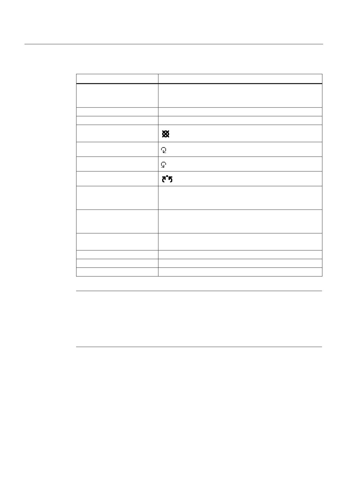
Working in manual mode
3.2 Selecting a tool and spindle
Display
Meaning
T
Input of the tool (name or location number)
You can select a tool from the tool list using the "Select tool"
softkey.
D
Cutting edge number of the tool (1 - 9)
Spindle
Spindle selection, identification with spindle number
Spindle M function
Other M functions
Input of machine functions
Refer to the machine manufacturer's table for the correlation
between the meaning and number of the function.
G work offset
Selection of the work offset (basic reference, G54 - 57)
You can select work offsets from the tool list of settable work
offsets via the "Work offset" softkey.
Unit of measurement
Selection of the unit of measurement (inch, mm)
The setting made here has an effect on the programming.
Machining plane
Selection of the machining plane (G17(XY), G18 (ZX), G19 (YZ))
Gear stage
Specification of the gear stage (auto, I - V)
Stop position
Input of the spindle position in degrees
Note
Spindle positioning
You can use this function to position the spindle at a specific angle, e.g. during a tool
change.
• A stationary spindle is positioned via the shortest possible route.
• A rotating spindle is positioned as it continues to turn in the same direction.
Universal
80
Operating Manual, 03/2013, 6FC5398-6AP40-3BA1
Working in manual mode
3.2 Selecting a tool and spindle
3.2.2
Selecting a tool
Procedure
1.
Select the "JOG" operating mode.
2.
Press the "T, S, M" softkey.
3.
Enter the name or the number of the tool T in the input field.
- OR -
Press the "Select tool" softkey to open the tool list, position the cursor
on the desired tool and press the "In Manual" softkey.
The tool is transferred to the "T, S, M... window" and displayed in the
field of tool parameter "T".
4.
Select tool edge D or enter the number directly in field "D".
5.
Press the <CYCLE START> key.
The tool is loaded into the spindle.
3.2.3
Starting and stopping a spindle manually
Procedure
1.
Select the "JOG" operating mode.
2.
Press the "T, S, M" softkey.
Universal
Operating Manual, 03/2013, 6FC5398-6AP40-3BA1
81
Working in manual mode
3.2 Selecting a tool and spindle
3.
Select the desired spindle (e.g. S1) and enter the desired spindle speed
(rpm) in the adjacent input field.
The spindle remains stationary.
4.
If the machine has a gearbox for the spindle, set the gear stage (e.g.
auto).
5.
Select a spindle direction of rotation (clockwise or counterclockwise) in
the "Spindle M function" field.
6.
Press the <CYCLE START> key.
The spindle rotates.
7.
Select the "Stop" setting in the "Spindle M function" field.
Press the <CYCLE START> key.
The spindle stops.
Note
Changing the spindle speed
If you enter the speed in the "Spindle" field while the spindle is rotating, the new speed is
applied.
3.2.4
Position spindle
Procedure
1.
Select the "JOG" operating mode.
2.
Press the "T, S, M" softkey.
3.
Select the "Stop Pos." setting in the "Spindle M function" field.
The "Stop Pos." entry field appears.
Universal
82
Operating Manual, 03/2013, 6FC5398-6AP40-3BA1
Working in manual mode
3.2 Selecting a tool and spindle
4.
Enter the desired spindle stop position.
The spindle position is specified in degrees.
5.
Press the <CYCLE START> key.
The spindle is moved to the desired position.
Note
You can use this function to position the spindle at a specific angle, e.g. during a tool
change.
• A stationary spindle is positioned via the shortest possible route.
• A rotating spindle is positioned as it continues to turn in the same direction.
Universal
Operating Manual, 03/2013, 6FC5398-6AP40-3BA1
83
Working in manual mode
3.3 Traversing axes
3.3
Traversing axes
You can traverse the axes in manual mode via the Increment or Axis keys or handwheels.
During a traverse initiated from the keyboard, the selected axis moves at the programmed
setup feedrate. During an incremental traverse, the selected axis traverses a specified
increment.
Set the default feedrate
Specify the feedrate to be used for axis traversal in the set-up, in the "Settings for Manual
Operation" window.
3.3.1
Traverse axes by a defined increment
You can traverse the axes in manual mode via the Increment and Axis keys or handwheels.
Procedure
1.
Select the "Machine" operating area.
2.
Press the <JOG> key.
3.
Press keys 1, 10, etc. up to 10000 in order to move the axis in a defined
increment.
The numbers on the keys indicate the traverse path in micrometers or
microinches.
Example: Press the "100" button for a desired increment of 100 μm (=
0.1 mm).
4.
Select the axis to be traversed.
;
=
5.
Press the <+> or <-> key.
Each time you press the key the selected axis is traversed by the
defined increment.
Feedrate and rapid traverse override switches can be operative.
Universal
84
Operating Manual, 03/2013, 6FC5398-6AP40-3BA1
Working in manual mode
3.3 Traversing axes
Note
When the controller is switched on, the axes can be traversed right up to the limits of the
machine as the reference points have not yet been approached and the axes referenced.
Emergency limit switches might be triggered as a result.
The software limit switches and the working area limitation are not yet operative!
The feed enable signal must be set.
Machine manufacturer
Please refer to the machine manufacturer's specifications.
3.3.2
Traversing axes by a variable increment
Procedure
1.
Select the "Machine" operating area.
Press the <JOG> key.
2.
Press the "Settings" softkey.
The "Settings for Manual Operation" window is opened.
3.
Enter the desired value for the "Variable increment" parameter.
Example: Enter 500 for a desired increment of 500 μm (0.5 mm).
4.
Press the <Inc VAR> key.
5.
Select the axis to be traversed.
6.
Press the <+> or <-> key.
Each time you press the key the selected axis is traversed by the set
increment.
Feedrate and rapid traverse override switches can be operative.
Universal
Operating Manual, 03/2013, 6FC5398-6AP40-3BA1
85
Working in manual mode
3.4 Positioning axes
3.4
Positioning axes
In manual mode, you can traverse individual or several axes to certain positions in order to
implement simple machining sequences.
The feedrate / rapid traverse override is active during traversing.
Procedure
1.
If required, select a tool.
2.
Select the "JOG" operating mode.
3.
Press the "Positions" softkey.
4.
Specify the desired value for the feedrate F.
- OR -
Press the "Rapid traverse" softkey.
The rapid traverse is displayed in field "F".
5.
Enter the target position or target angle for the axis or axes to be
traversed.
6.
Press the <CYCLE START> key.
The axis is traversed to the specified target position.
If target positions were specified for several axes, the axes are
traversed simultaneously.
Universal
86
Operating Manual, 03/2013, 6FC5398-6AP40-3BA1
Working in manual mode
3.5 Manual retraction
3.5
Manual retraction
After an interruption of a tapping operation (G33/G331/G332) or a general drilling operation
(tools 200 to 299) due to power loss or a RESET at the machine control panel, you have the
possibility to retract the tool in the JOG mode in the tool direction without damaging the tool
or the workpiece.
The retraction function is especially useful when the coordinate system is swiveled, i.e. the
infeed axis is not in the vertical position.
Note
Tapping
In the case of tapping, the form fit between the tap and the workpiece is taken into account
and the spindle moved according to the thread.
The Z axis as well as the spindle can be used for retraction at the thread.
The "Retraction" function must be set up by the machine manufacturer.
Machine manufacturer
Please refer to the machine manufacturer's specifications.
Procedure
1.
<RESET> interrupts the power supply to the machine and any running
part program.
2.
After a power supply interruption, switch on the controller.
3.
Select the JOG operating mode.
4.
Press the Menu forward key.
5.
Press the "Retract" softkey.
The "Retract Tool" window opens.
The softkey is available only when an active tool and retraction data are
present.
6.
Select the "WCS" coordinate system on the machine control panel.
Universal
Operating Manual, 03/2013, 6FC5398-6AP40-3BA1
87
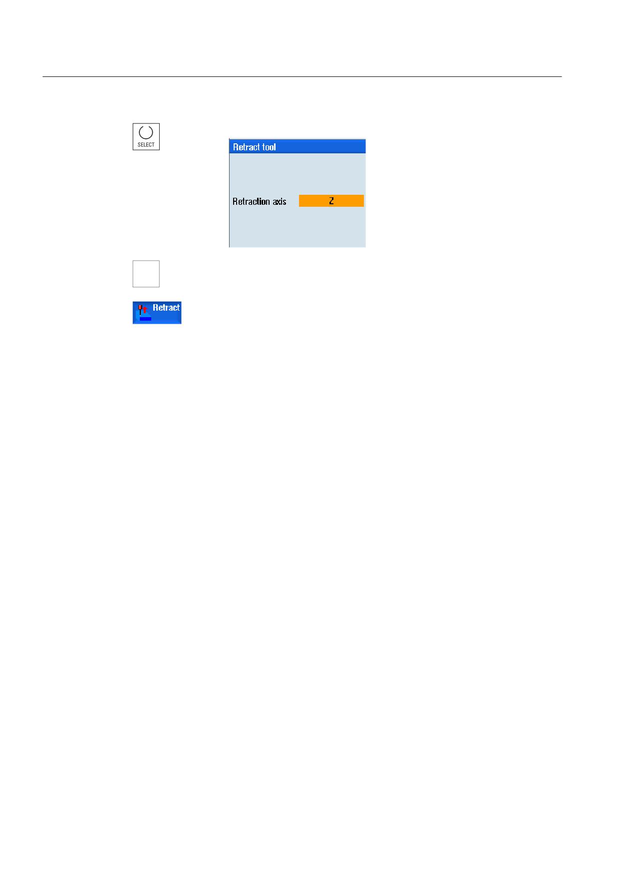
Working in manual mode
3.5 Manual retraction
7.
Select the required axis in the "Retraction axis" selection box.
8.
Use the traversing keys (e.g. Z +) to traverse the tool from the
=
workpiece according to the retraction axis selected in the "Retract Tool"
window.
9.
To exit the window, press the "Retract" softkey again when the tool is at
the desired position.
Universal
88
Operating Manual, 03/2013, 6FC5398-6AP40-3BA1
Working in manual mode
3.6 Default settings for manual mode
3.6
Default settings for manual mode
Specify the configurations for manual mode in the "Settings for manual operation" window.
Presettings
Settings
Description
Type of feedrate
Here, you select the type of feedrate.
• G94: Axis feedrate/linear feedrate
• G95: Rev. feedrate
Default feedrate G94
Enter the desired feedrate in mm/min.
Default feedrate G95
Enter the desired feedrate in mm/r.
Variable increment
Enter the desired increment for axis traversal by variable increments.
Spindle speed
Enter the desired spindle speed in rpm.
Proceed as follows
1.
Select the "Machine" operating area.
2.
Press the <JOG> key.
3.
Press the menu forward key and the "Settings" softkey.
The "Settings for manual operation" window is opened.
Universal
Operating Manual, 03/2013, 6FC5398-6AP40-3BA1
89
Working in manual mode
3.6 Default settings for manual mode
Universal
90
Operating Manual, 03/2013, 6FC5398-6AP40-3BA1
Machining the workpiece
4
4.1
Starting and stopping machining
During execution of a program, the workpiece is machined in accordance with the
programming on the machine. After the program is started in automatic mode, workpiece
machining is performed automatically.
Requirements
The following requirements must be met before executing a program:
● The measuring system of the controller is referenced with the machine.
● The necessary tool offsets and zero offsets have been entered.
● The necessary safety interlocks implemented by the machine manufacturer are activated.
General sequence
1.
Use the Program manager to select the desired program.
Select the desired program under "NC", "Local drive", "USB" or set-up
network drives.
3.
Press the "Select" softkey.
The program is selected for execution and automatically switched to the
"Machine" operating area.
4.
Press the <CYCLE START> key.
The program is started and executed.
Note
Starting the program in any operating area
If the controller is in "AUTO" mode, you can also start the selected program when you are in
any operating area.
Universal
Operating Manual, 03/2013, 6FC5398-6AP40-3BA1
91
Machining the workpiece
4.1 Starting and stopping machining
Stopping machining
Press the <CYCLE STOP> key.
Machining stops immediately. Individual program blocks are not
executed to the end. On the next start, machining is resumed
from the point where it left off.
Canceling machining
Press the <RESET> key.
Execution of the program is interrupted. On the next start, machining
will start from the beginning.
Machine manufacturer
Please refer to the machine manufacturer's specifications.
See also
EXTCALL (Page 255)
Universal
92
Operating Manual, 03/2013, 6FC5398-6AP40-3BA1
Machining the workpiece
4.2 Selecting a program
4.2
Selecting a program
Procedure
1.
Select the "Program manager" operating area.
The directory overview is opened.
2.
Place the cursor on the directory containing the program that you want
to select.
3.
Press the <INPUT> key
- OR -
Press the <Cursor right> key.
The directory contents are displayed.
4.
Place the cursor on the desired program.
5.
Press the "Select" softkey.
The program is selected.
When the program has been successfully selected, an automatic
changeover to the "Machine" operating area occurs.
Universal
Operating Manual, 03/2013, 6FC5398-6AP40-3BA1
93
Machining the workpiece
4.3 Program running-in
4.3
Program running-in
When testing a program, the system can interrupt the machining of the workpiece after each
program block, which triggers a movement or auxiliary function on the machine. In this way,
you can control the machining result block-by-block during the initial execution of a program
on the machine.
Note
Settings for the automatic mode
Rapid traverse reduction and dry run feed rate are available to run-in or to test a program.
Move by single block
In "Program control" you may select from among several types of block processing:
SB mode
Scope
SB1 Single block,
The machining stops after every machine block (except for cycles)
coarse
SB2 Data block
The machining stops after every block, i.e. also for data blocks (except for
cycles)
SB3 Single block,
The machining stops after every machine block (also in cycles)
fine
Precondition
A program must be selected for execution in "AUTO" or "MDA" mode.
Procedure
1.
Press the "Prog. ctrl." softkey and select the desired variant in the "SBL"
field.
2.
Press the <SINGLE BLOCK> key.
3.
Press the <CYCLE START> key.
Depending on the execution variant, the first block will be executed.
Then the machining stops.
In the channel status line, the text “Stop: Block in single block ended"
appears.
4.
Press the <CYCLE START> key.
Depending on the mode, the program will continue executing until the
next stop.
Universal
94
Operating Manual, 03/2013, 6FC5398-6AP40-3BA1

Machining the workpiece
4.4 Displaying the current program block
5.
Press the <SINGLE BLOCK> key again, if the machining is not
supposed to run block-by-block.
The key is deselected again.
If you now press the <CYCLE START> key again, the program is
executed to the end without interruption.
See also
Selecting a program (Page 93)
4.4
Displaying the current program block
4.4.1
Current block display
The window of the current block display shows you the program blocks currently being
executed.
Display of current program
The following information is displayed in the running program:
● The workpiece name or program name is entered in the title row.
● The program block which is just being processed appears colored.
Editing a program directly
In the Reset state, you can edit the current program directly.
1.
Press the <INSERT> key.
2.
Place the cursor at the relevant position and edit the program block.
Direct editing is only possible for G code blocks in the NC memory, not
for external execution.
3.
Press the <INSERT> key to exit the program and the edit mode again.
Universal
Operating Manual, 03/2013, 6FC5398-6AP40-3BA1
95
Machining the workpiece
4.4 Displaying the current program block
4.4.2
Displaying a basic block
If you want precise information about axis positions and important G functions during testing
or program execution, you can call up the basic block display. This is how you can check,
when using cycles, for example, whether the machine is actually traversing.
Positions programmed by means of variables or R parameters are resolved in the basic
block display and replaced by the variable value.
You can use the basic block display both in test mode and when machining the workpiece on
the machine. All G code commands that initiate a function on the machine are displayed in
the "Basic Blocks" window for the currently active program block:
● Absolute axis positions
● G functions for the first G group
● Other modal G functions
● Other programmed addresses
● M functions
Machine manufacturer
Please refer to the machine manufacturer's specifications.
Procedure
1.
A program is selected for execution and has been opened in the
"Machine" operating area.
2.
Press the "Basic blocks" softkey.
The "Basic Blocks" window opens.
3.
Press the <SINGLE BLOCK> key if you wish to execute the program
block-by-block.
4.
Press the <CYCLE START> key to start the program execution.
The axis positions to be approached, modal G functions, etc., are
displayed in the "Basic Blocks" window for the currently active program
block.
5.
Press the "Basic blocks" softkey once again to hide the window again.
Universal
96
Operating Manual, 03/2013, 6FC5398-6AP40-3BA1
Machining the workpiece
4.4 Displaying the current program block
4.4.3
Display program level
You can display the current program level during the execution of a large program with
several subprograms.
Several program run throughs
If you have programmed several program run throughs, i.e. subprograms are run through
several times one after the other by specifying the additional parameter P, then during
processing, the program runs still to be executed are displayed in the "Program Levels"
window.
Program example
N10 subprogram P25
If, in at least one program level, a program is run through several times, a horizontal scroll
bar is displayed that allows the run through counter P to be viewed in the righthand window
section. The scroll bar disappears if multiple run-through is no longer applicable.
Display of program level
The following information will be displayed:
● Level number
● Program name
● Block number, or line number
● Remain program run throughs (only for several program run throughs)
Precondition
A program must be selected for execution in "AUTO" mode.
Procedure
Press the "Program levels" softkey.
The "Program levels" window appears.
Universal
Operating Manual, 03/2013, 6FC5398-6AP40-3BA1
97
Machining the workpiece
4.5 Correcting a program
4.5
Correcting a program
As soon as a syntax error in the part program is detected by the controller, program
execution is interrupted and the syntax error is displayed in the alarm line.
Correction possibilities
Depending on the state of the control system, you can make the following corrections using
the Program editing function.
● Stop mode
Only program lines that have not yet been executed can be edited.
● Reset mode
All program lines can be edited.
Note
The "program correction" function is also available for execute from external; however,
when making program changes, the NC channel must be brought into the reset state.
Requirement
A program must be selected for execution in "AUTO" mode.
Procedure
1.
The program to be corrected is in the Stop or Reset mode.
2.
Press the "Prog. corr.” softkey
The program is opened in the editor.
The program preprocessing and the current block are displayed. The
current block is also updated in the running program, but not the
displayed program section, i.e. the current block moves out of the
displayed program section.
If a subprogram is executed, it is not opened automatically.
3.
Make the necessary corrections.
4.
Press the "NC Execute" softkey.
The system switches back to the "Machine" operating area and selects
"AUTO" mode.
5.
Press the <CYCLE START> key to resume program execution.
Universal
98
Operating Manual, 03/2013, 6FC5398-6AP40-3BA1
Machining the workpiece
4.6 Repositioning axes
Note
Exit the editor using the "Close" softkey to return to the "Program manager" operating area.
4.6
Repositioning axes
After a program interruption in automatic mode (e.g. after a tool breaks) you can move the
tool away from the contour in manual mode.
The coordinates of the interrupt position will be saved. The distances traversed in manual
mode are displayed in the actual value window. This path difference is called "Repos-offset".
Resuming program execution
Using the "Repos" function, you can return the tool to the contour in order to continue
executing the program.
You cannot traverse the interrupt position, because it is blocked by the control system.
The feedrate/rapid traverse override is in effect
NOTICE
Risk of collision
When repositioning, the axes move with the programmed feedrate and linear interpolation,
i.e. in a straight line from the current position to the interrupt point. Therefore, you must first
move the axes to a safe position in order to avoid collisions.
If you do not use the "Repos" function and subsequently move the axes in manual mode
after a program interrupt, the control automatically moves the axes during the switch to
automatic mode and the subsequent start of the machining process in a straight line back
to the point of interruption.
Precondition
The following prerequisites must be met when repositioning the axes:
● The program execution was interrupted using <CYCLE STOP>.
● The axes were moved from the interrupt point to another position in manual mode.
Universal
Operating Manual, 03/2013, 6FC5398-6AP40-3BA1
99
//////////////////////////////////////////