SINUMERIK 840D sl/828D Universal. Operating Manual (2013) - page 2
Machining the workpiece
4.6 Repositioning axes
Procedure
1.
Press the <REPOS> key.
2.
Select the axes to be traversed one after the other.
;
=
3.
Press the <+> or <-> key for the relevant direction.
The axes are moved to the interrupt position.
Universal
100
Operating Manual, 03/2013, 6FC5398-6AP40-3BA1
Machining the workpiece
4.7 Starting execution at a specific point
4.7
Starting execution at a specific point
4.7.1
Use block search
If you would only like to perform a certain section of a program on the machine, then you
need not start the program from the beginning. You can also start the program from a
specified program block.
Applications
● Stopping or interrupting program execution
● Specify a target position, e.g. during remachining
Determining a search target
● User-friendly search target definition (search positions)
- Direct specification of the search target by positioning the cursor in the selected
program (main program)
- Search target via text search
- The search target is the interruption point (main program and subprogram)
The function is only available if there is an interruption point. After a program
interruption (CYCLE STOP or RESET), the controller saves the coordinates of the
interruption point.
- The search target is the higher program level of the interruption point (main program
and subprogram)
The level can only be changed if it was previously possible to select an interruption
point in a subprogram. It is then possible to change the program level up to the main
program level and back to the level of the interruption point.
● Search pointer
- Direct entry of the program path
Note
You can search for a specific point in subprograms with the search pointer if there is
no interruption point.
Software option
You require the "Extended operator functions" option for the "Search pointer"
function (only for 828D).
Universal
Operating Manual, 03/2013, 6FC5398-6AP40-3BA1
101
Machining the workpiece
4.7 Starting execution at a specific point
Cascaded search
You can start another search from the "Search target found" state. The cascading can be
continued any number of times after every search target found.
Note
Another cascaded block search can be started from the stopped program execution only if
the search target has been found.
References
Function Manual Basic Functions; Block Search
Preconditions
1. You have selected the desired program.
2. The controller is in the reset state.
3. The desired search mode is selected.
NOTICE
Risk of collision
Pay attention to a collision-free start position and appropriate active tools and other
technological values.
If necessary, manually approach a collision-free start position. Select the target block
considering the selected block search type.
Toggling between search pointer and search positions
Press the "Search pointer" softkey again to exit the "Search Pointer"
window and return to the "Program" window to define search positions.
- OR -
Press the "Back" softkey.
You have now exited the block search function.
See also
Block search mode (Page 107)
Selecting a program (Page 93)
Universal
102
Operating Manual, 03/2013, 6FC5398-6AP40-3BA1
Machining the workpiece
4.7 Starting execution at a specific point
4.7.2
Continuing program from search target
To continue the program at the desired position, press the <CYCLE START> key twice.
● The first CYCLE START outputs the auxiliary functions collected during the search. The
program is then in the Stop state.
● Before the second CYCLE START, you can use the "Overstore" function to create states
that are required, but not yet available, for the further program execution.
By changing to the JOG REPOS mode, you can also manually traverse the tool from the
current position to the setpoint position, if the setpoint position is not to be automatically
approached after the program start
4.7.3
Simple search target definition
Requirement
The program is selected and the controller is in Reset mode.
Procedure
1.
Press the "Block search" softkey.
2.
Place the cursor on a particular program block.
- OR -
Press the "Find text" softkey, select the search direction, enter the
search text and confirm with "OK".
3.
Press the "Start search" softkey.
The search starts. Your specified search mode will be taken into
account.
The current block will be displayed in the "Program" window as soon
as the target is found.
4.
If the located target (for example, when searching via text) does not
correspond to the program block, press the "Start search" softkey
again until you find your target.
Press the <CYCLE START> key twice.
Processing is continued from the defined position.
Universal
Operating Manual, 03/2013, 6FC5398-6AP40-3BA1
103
Machining the workpiece
4.7 Starting execution at a specific point
4.7.4
Defining an interruption point as search target
Requirement
A program was selected in "AUTO" mode and interrupted during execution through CYCLE
STOP or RESET.
Software option
You require the "Extended operator functions" option (only for 828D).
Procedure
1.
Press the "Block search" softkey.
2.
Press the "Interrupt point" softkey.
The interruption point is loaded.
3.
If the "Higher level" and "Lower level" softkeys are available, use these
to change the program level.
4.
Press the "Start search" softkey.
The search starts. Your specified search mode will be taken into
account.
The search screen closes.
The current block will be displayed in the "Program" window as soon as
the target is found.
5.
Press the <CYCLE START> key twice.
The execution will continue from the interruption point.
Universal
104
Operating Manual, 03/2013, 6FC5398-6AP40-3BA1
Machining the workpiece
4.7 Starting execution at a specific point
4.7.5
Entering the search target via search pointer
Enter the program point which you would like to proceed to in the "Search Pointer" window.
Software option
You require the "Extended operator functions" option for the "Search pointer"
function (only for 828D).
Requirement
The program is selected and the controller is in the reset state.
Screen form
Each line represents one program level. The actual number of levels in the program depends
on the nesting depth of the program.
Level 1 always corresponds to the main program and all other levels correspond to
subprograms.
You must enter the target in the line of the window corresponding to the program level in
which the target is located.
For example, if the target is located in the subprogram called directly from the main program,
you must enter the target in program level 2.
The specified target must always be unambiguous. This means, for example, that if the
subprogram is called in the main program in two different places, you must also specify a
target in program level 1 (main program).
Procedure
1.
Press the "Block search" softkey.
2.
Press the "Search pointer" softkey.
3.
Enter the full path of the program as well as the subprograms, if
required, in the input fields.
4.
Press the "Start search" softkey.
The search starts. Your specified search mode will be taken into
account.
Universal
Operating Manual, 03/2013, 6FC5398-6AP40-3BA1
105
Machining the workpiece
4.7 Starting execution at a specific point
The Search window closes. The current block will be displayed in the
"Program" window as soon as the target is found.
5.
Press the <CYCLE START> key twice.
Processing is continued from the defined location.
Note
Interruption point
You can load the interruption point in search pointer mode.
4.7.6
Parameters for block search in the search pointer
Parameter
Meaning
Number of program level
Program:
The name of the main program is automatically entered
Ext:
File extension
P:
Pass counter
If a program section is performed several times, you can enter the number of
the pass here at which processing is to be continued
Line:
Is automatically filled for an interruption point
Type
" " search target is ignored on this level
N no. Block number
Label Jump label
Text string
Subprg. Subprogram call
Line Line number
Search target
Point in the program at which machining is to start
Universal
106
Operating Manual, 03/2013, 6FC5398-6AP40-3BA1
Machining the workpiece
4.7 Starting execution at a specific point
4.7.7
Block search mode
Set the desired search variant in the "Search Mode" window.
The set mode is retained when the the controller is shut down. When you activate the
"Search" function after restarting the controller, the current search mode is displayed in the
title row.
Search variants
Block search mode
Meaning
With calculation
It is used in order to be able to approach a target position in any
circumstance (e.g. tool change position).
- without approach
The end position of the target block or the next programmed position is
approached using the type of interpolation valid in the target block. Only the
axes programmed in the target block are moved.
Note:
If machine data 11450.1=1 is set, the rotary axes of the active swivel data
record are pre-positioned after the block search.
With calculation
It is used to be able to approach the contour in any circumstance.
- with approach
The end position of the block prior to the target block is found with <CYCLE
START>. The program runs in the same way as in normal program
processing.
With calculation
This is used to speed-up a search with calculation when using EXTCALL
programs: EXTCALL programs are not taken into account.
- skip extcall
Notice: Important information, e.g. modal functions, which are located in the
EXTCALL program, are not taken into account. In this case, after the
search target has been found, the program is not able to be executed.
Information such as this should be programmed in the main program.
Without calculation
For a quick search in the main program.
Calculations will not be performed during the block search, i.e. the
calculation is skipped up to the target block.
All settings required for execution have to be programmed from the target
block (e.g. feedrate, spindle speed, etc.).
With program test
Multi-channel block search with calculation (SERUPRO).
All blocks are calculated during the block search. Absolutely no axis motion
is executed, however, all auxiliary functions are output.
The NC starts the selected program in the program test mode. If the NC
reaches the specified target block in the actual channel, it stops at the
beginning of the target block and deselects program test mode again. After
continuing the program with NC start (after REPOS motion) the auxiliary
functions of the target block are output.
For single-channel systems, the coordination is supported with events
running in parallel, e.g. synchronized actions.
Note
The search speed depends on MD settings.
Universal
Operating Manual, 03/2013, 6FC5398-6AP40-3BA1
107

Machining the workpiece
4.7 Starting execution at a specific point
Note
Search mode for the ShopMill and ShopTurn programs
The search variant for the ShopMill/ShopTurn machining step programs can be specified via
MD 51024. This applies only to the ShopMill/ShopTurn single-channel view.
Machine manufacturer
Please refer to the machine manufacturer's specifications.
References
For additional information, please refer to the following documentation:
Commissioning Manual SINUMERIK Operate (IM9) / SINUMERIK 840D sl
Procedure
1.
Select the "Machine" operating area.
2.
Press the <AUTO> key.
3.
Press the "Block search" and "Block search mode" softkeys.
The "Search Mode" window appears.
Universal
108
Operating Manual, 03/2013, 6FC5398-6AP40-3BA1
Machining the workpiece
4.8 Controlling the program run
4.8
Controlling the program run
4.8.1
Program control
You can change the program sequence in the "AUTO" and "MDI" modes.
Abbreviation/program
Mode of operation
control
PRT
The program is started and executed with auxiliary function outputs and dwell times. In this
mode, the axes are not traversed.
no axis motion
The programmed axis positions and the auxiliary function outputs are controlled this way.
Note: Program processing without axis motion can also be activated with the function "Dry
run feedrate".
DRY
The traversing velocities programmed in conjunction with G1, G2, G3, CIP and CT are
replaced by a defined dry run feedrate. The dry run feedrate also applies instead of the
Dry run feedrate
programmed revolutional feedrate.
Caution: Workpieces must not be machined when "Dry run feedrate" is active because the
altered feedrates might cause the permissible tool cutting rates to be exceeded and the
workpiece or machine tool could be damaged.
RG0
In the rapid traverse mode, the traversing speed of the axes is reduced to the percentage
value entered in RG0.
Reduced rapid traverse
Note: You define the reduced rapid traverse in the settings for automatic operation.
M01
The processing of the program stops at every block in which supplementary function M01 is
programmed. In this way you can check the already obtained result during the processing of
Programmed stop 1
a workpiece.
Note: In order to continue executing the program, press the <CYCLE START> key again.
Programmed stop 2
The processing of the program stops at every block in which the "Cycle end" is programmed
(e.g. with M101).
(e.g. M101)
Note: In order to continue executing the program, press the <CYCLE START> key again.
Note: The display can be changed. Please refer to the machine manufacturer's
specifications.
DRF
Enables an additional incremental zero offset while processing in automatic mode with an
electronic handwheel.
Handwheel offset
This function can be used to compensate for tool wear within a programmed block.
Note: You require the "Extended operator functions" option to use the handwheel offset (for
828D).
SB
Individual blocks are configured as follows.
Single block, coarse: The program stops only after blocks which perform a machine function.
Data block: The program stops after each block.
Single block, fine: The program also only stops after blocks which perform a machine function
in cycles.
Select the desired setting using the <SELECT> key.
SKP
Skip blocks are skipped during machining.
GCC
When executing a jobshop program, it is converted into a G-code program.
Universal
Operating Manual, 03/2013, 6FC5398-6AP40-3BA1
109
Machining the workpiece
4.8 Controlling the program run
Activating program control
You can control the program sequence however you wish by selecting and clearing the
relevant checkboxes.
Display / response of active program controls:
If a program control is activated, the abbreviation of the corresponding function appears in
the status display as response.
Procedure
1.
Select the "Machine" operating area.
2.
Press the <AUTO> or <MDI> key.
3.
Press the "Prog. ctrl.” softkey.
The "Program Control" window appears.
4.8.2
Skip blocks
It is possible to skip program blocks, which are not to be executed every time the program
runs.
The skip blocks are identified by placing a "/" (forward slash) or "/x (x = number of skip level)
character in front of the block number. Several consecutive blocks can also be skipped.
The statements in the skipped blocks are not executed, i.e. the program continues with the
next block, which is not skipped.
The number of skip levels that can be used depends on a machine datum.
Machine manufacturer
Please refer to the machine manufacturer's specifications.
Software option
In order to have more than two skip levels, for 828D you require the
"Extended operator functions" option.
Universal
110
Operating Manual, 03/2013, 6FC5398-6AP40-3BA1
Machining the workpiece
4.8 Controlling the program run
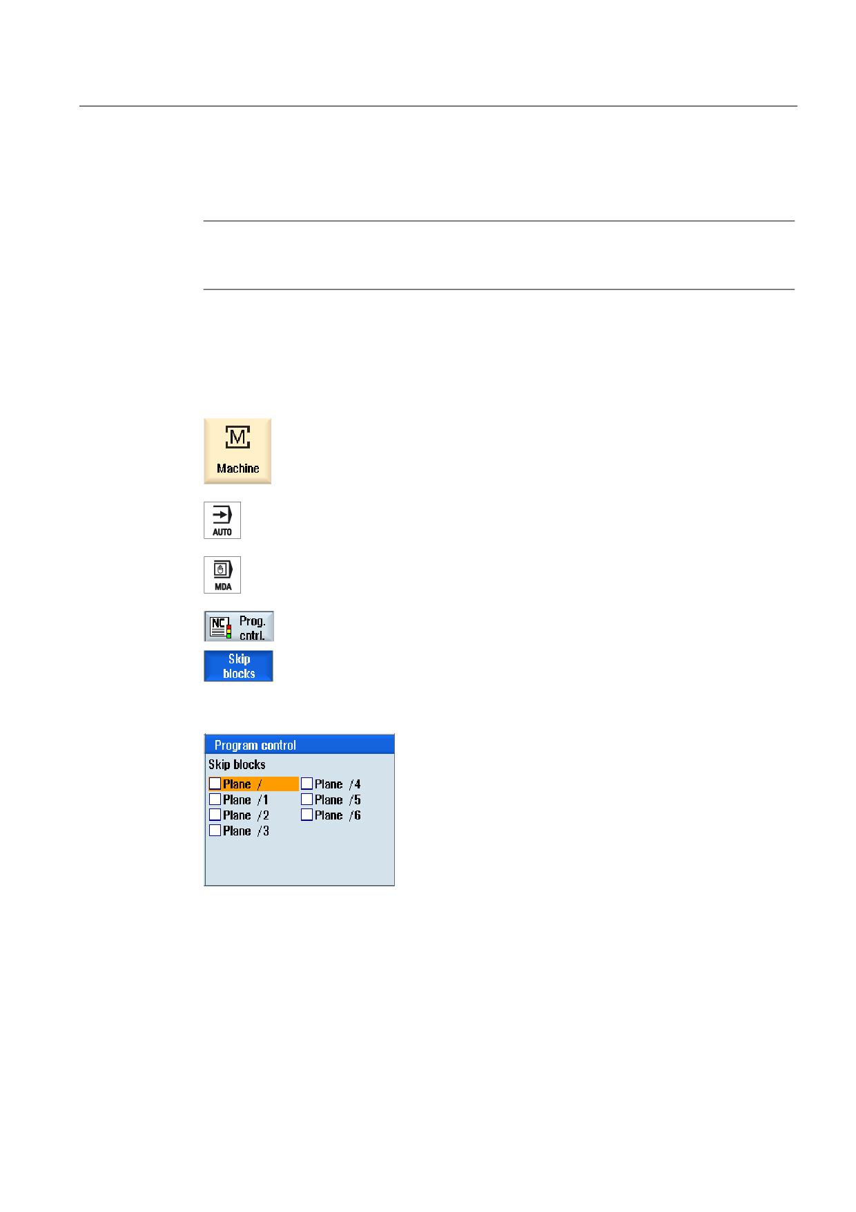
Skip levels, activate
Select the corresponding checkbox to activate the desired skip level.
Note
The "Program Control - Skip Blocks" window is only available when more than one skip level
is set up.
Procedure
1.
Select the "Machine" operating area.
2.
Press the <AUTO> or <MDA> key.
3
Press the "Prog. ctrl." and "Skip blocks" softkeys.
The "Program Control" window appears and shows a list of skip levels.
Universal
Operating Manual, 03/2013, 6FC5398-6AP40-3BA1
111
Machining the workpiece
4.9 Overstore
4.9
Overstore
With overstore, you have the option of executing technological parameters (for example,
auxiliary functions, axis feed, spindle speed, programmable instructions, etc.) before the
program is actually started. The program instructions act as if they are located in a normal
part program. These program instructions are, however, only valid for one program run. The
part program is not permanently changed. When next started, the program will be executed
as originally programmed.
After a block search, the machine can be brought into another state with overstore (e.g. M
function, tool, feed, speed, axis positions etc.), in which the normal part program can be
successfully continued.
Software option
You require the "Extended operator functions" option for the overstore function
(for 828D).
Precondition
The program to be corrected is in the Stop or Reset mode.
Procedure
1.
Open the program in the "AUTO" mode.
2.
Press the "Overstore" softkey.
The "Overstore" window opens.
3.
Enter the required data and NC block.
4.
Press the <CYCLE START> key.
The blocks you have entered are stored. You can observe execution in
the "Overstore" window.
After the entered blocks have been executed, you can append blocks
again.
You cannot change the operating mode while you are in overstore
mode.
5.
Press the "Back" softkey.
The "Overstore" window closes.
6.
Press the <CYCLE START> key again.
The program selected before overstoring continues to run.
Universal
112
Operating Manual, 03/2013, 6FC5398-6AP40-3BA1

Machining the workpiece
4.10 Editing a program
Note
Block-by-block execution
The <SINGLE BLOCK> key is also active in the overstore mode. If several blocks are
entered in the overstore buffer, then these are executed block-by-block after each NC start
Deleting blocks
Press the "Delete blocks" softkey to delete program blocks you have
entered.
4.10
Editing a program
With the editor, you are able to render, supplement, or change part programs.
Note
Maximum block length
The maximum block length is 512 characters.
Calling the editor
● The editor is started via the "Program correction" function in the "Machine" operating area
and with the <INSERT> key.
● The editor is called via the "Open" softkey as well as with the <INPUT> or <Cursor right>
key in the "Program manager" operating area.
● The editor opens in the "Program" operating area with the last executed part program, if
this was not explicitly exited via the "Close" softkey.
Note
Please note that the changes to programs stored in the NC memory take immediate
effect. You can exit the editor only after you have saved the changes.
If you are editing on a local drive or external drives, you can also exit the editor without
saving, depending on the setting.
Exit the program correction mode using the "Close" softkey to return to the "Program
manager" operating area.
Universal
Operating Manual, 03/2013, 6FC5398-6AP40-3BA1
113
Machining the workpiece
4.10 Editing a program
See also
Editor settings (Page 121)
Opening and closing a program (Page 230)
Correcting a program (Page 98)
4.10.1
Searching in programs
You can use the search function to quickly arrive at points where you would like to make
changes, e.g. in very large programs.
Various search options are available that enable selective searching.
Search options
● Whole words
Activate this option and enter a search term if you want to search for texts/terms that are
present as words in precisely this form.
If, for example, you enter the search term "Finishing tool", only single "Finishing tool"
terms are displayed.
● Exact expression
Activate this option if you want to search for place holders in program lines (e.g. "*" or "?")
that you want to replace.
Note
Search with place holders
When searching for specific program locations, you have the option of using place holders:
• "*": Replaces any character string
• "?": Replaces any character
Requirement
The desired program is opened in the editor.
Procedure
1.
Press the "Search" softkey.
A new vertical softkey bar appears.
The "Search" window opens at the same time.
2.
Enter the desired search term in the "Text" field.
3.
Select "Whole words" if you want to search for whole words only.
Universal
114
Operating Manual, 03/2013, 6FC5398-6AP40-3BA1
Machining the workpiece
4.10 Editing a program
- OR -
Activate the "Exact expression" checkbox if, for example, you want to
search for place holders ("*", "?") in program lines.
4.
Position the cursor in the "Direction" field and choose the search
direction (forward, backward) with the <SELECT> key.
5.
Press the "OK" softkey to start the search.
If the text you are searching for is found, the corresponding line is
highlighted.
6.
Press the "Continue search" softkey if the text located during the search
does not correspond to the point you are looking for.
- OR -
Press the "Cancel" softkey when you want to cancel the search.
Further search options
Softkey
Function
The cursor is set to the first character in the program.
The cursor is set to the last character in the program.
4.10.2
Replacing program text
You can find and replace text in one step.
Requirement
The desired program is opened in the editor.
Procedure
1.
Press the "Search" softkey.
A new vertical softkey bar appears.
2.
Press the "Find and replace" softkey.
The "Find and Replace" window appears.
Universal
Operating Manual, 03/2013, 6FC5398-6AP40-3BA1
115
Machining the workpiece
4.10 Editing a program
3.
In the "Text" field, enter the term you are looking for and in the "Replace
with" field, enter the text you would like to insert automatically during the
search.
4.
Position the cursor in the "Direction" field and choose the search
direction (forward, backward) with the <SELECT> key.
5.
Press the "OK" softkey to start the search.
If the text you are searching for is found, the corresponding line is
highlighted.
6.
Press the "Replace" softkey to replace the text.
- OR -
Press the "Replace all" softkey to replace all text in the file that
corresponds to the search term.
- OR -
Press the "Continue search" softkey if the text located during the search
should not be replaced.
- OR -
Press the "Cancel" softkey when you want to cancel the search.
Note
Replacing texts
• Read-only lines (;*RO*)
If hits are found, the texts are not replaced.
• Contour lines (;*GP*)
If hits are found, the texts are replaced as long as the lines are not read-only.
• Hidden lines (;*HD*)
If hidden lines are displayed in the editor and hits are found, the texts are replaced as
long as the lines are not read-only. Hidden lines that are not displayed, are not replaced.
See also
Editor settings (Page 121)
Universal
116
Operating Manual, 03/2013, 6FC5398-6AP40-3BA1
Machining the workpiece
4.10 Editing a program
4.10.3
Copying/pasting/deleting program blocks
Requirement
The program is opened in the editor.
Procedure
1.
Press the "Mark" softkey.
- OR -
Press the <SELECT> key.
2.
Select the desired program blocks with the cursor or mouse.
3.
Press the "Copy" softkey in order to copy the selection to the buffer
memory.
4.
Place the cursor on the desired insertion point in the program and press
the "Paste" softkey.
The content of the buffer memory is pasted.
- OR -
Press the "Cut" softkey to delete the selected program blocks.
Note: When editing a program, you cannot copy or cut more than 1024
lines. While a program that is not on the NC is opened (progress display
less than 100%), you cannot copy or cut more than 10 lines or insert
more than 1024 characters.
Note
The buffer memory contents are retained even after the editor is closed, enabling you to
paste the contents in another program, as well.
Note
Copy/cut current line
To copy and cut the current line where the cursor is positioned, it is not necessary to mark or
select it. You have the option of making the "Cut" softkey only operable for marked program
sections via editor settings.
Universal
Operating Manual, 03/2013, 6FC5398-6AP40-3BA1
117
Machining the workpiece
4.10 Editing a program
See also
Opening additional programs (Page 120)
4.10.4
Renumbering a program
You can modify the block numbering of programs opened in the editor at a later point in time.
Requirement
The program is opened in the editor.
Procedure
1.
Press the ">>" softkey.
A new vertical softkey bar appears.
2.
Press the "Renumber" softkey.
The "Renumbering" window appears.
3.
Enter the values for the first block number and the increment to be used
for numbering.
4.
Press the "OK" softkey.
The program is renumbered.
Note
If you only want to renumber a section, select the program blocks whose block numbering
you want to edit.
Universal
118
Operating Manual, 03/2013, 6FC5398-6AP40-3BA1
Machining the workpiece
4.10 Editing a program
4.10.5
Creating a program block
In order to structure programs in order to achieve a higher degree of transparency, you have
the option of combining several G-code blocks to form program blocks.
You then have the option of opening and closing these blocks depending on your
requirement.
Settings for a program block
Display
Meaning
Text
Block designation
Spindle
• S1
• S2
Spindle assignment. Defines at which spindle a program block is to be
executed.
Addit. run-in code
• Yes
For the case that the block is not executed, as the specified spindle should
not be processed, then it is possible to temporarily activate a so-called
"Addit. run-in code".
• No
Automat. Retraction
• Yes
Block start and block end are moved to the tool change point, i.e. the tool
is brought into a safe range.
• No
Procedure
1.
Select the "Program Manager" operating area.
2.
Select the storage location and create a program or open a program.
The program editor is opened.
3.
Select the required program blocks that you wish to combine to form a
block.
4.
Press the "Build group" softkey.
The "Build group" window is opened.
Universal
Operating Manual, 03/2013, 6FC5398-6AP40-3BA1
119
Machining the workpiece
4.10 Editing a program
5.
Enter a designation for the block, assign the spindle, if required, select
the Addit. run-in code and the automatic retraction and then press the
"OK" softkey.
Opening and closing blocks
6.
Press the ">>" and "View" softkeys.
7.
Press the "Open blocks" softkey if you wish to display the program with
all blocks.
8.
Press the "Close blocks" softkey, if you wish to display the program
again in a structured form.
4.10.6
Opening additional programs
You have the option of viewing and editing two programs simultaneously in the editor.
For instance, you can copy program blocks or machining steps of a program and paste them
into another program.
Opening several programs
You have the option of opening up to ten program blocks.
1.
In the program manager, select the programs that you wish to open and
view in the multiple editor and then press on the "Open" softkey.
The editor is opened and the first two programs are displayed.
2.
Press the <NEXT WINDOW> key to change to the next opened
program.
3.
Press the "Close" softkey to close the actual program.
Note
Pasting program blocks
JobShop machining steps cannot be copied into a G code program.
Requirement
You have opened a program in the editor.
Universal
120
Operating Manual, 03/2013, 6FC5398-6AP40-3BA1
Machining the workpiece
4.10 Editing a program
Procedure
1.
Press the ">>" and "Open additional program" softkeys.
The "Select Additional Program" window is opened.
2.
Select the program or programs that you wish to display in addition to
the already opened program.
3.
Press the "OK" softkey.
The editor opens and displays both programs next to each another.
See also
Copying/pasting/deleting program blocks (Page 117)
4.10.7
Editor settings
Enter the default settings in the "Settings" window that are to take effect automatically when
the editor is opened.
Defaults
Setting
Meaning
Number
• Yes: A new block number will automatically be assigned after every line
automatically
change. In this case, the specifications provided under "First block
number" and "Increment" are applicable.
• No: No automatic numbering.
First block number
Specifies the starting block number of a newly created program.
The field is only editable when "Yes" is displayed under "Number
automatically".
Increment
Defines the increment used for the block numbers.
The field is only editable when "Yes" is displayed under "Number
automatically".
Display hidden lines
• Yes: Hidden lines marked with "*HD" (hidden) will be displayed.
• No: Lines marked with ";*HD*" will not be displayed.
Note:
Only visible program lines are taken into account with the "Search" and
"Search and Replace" functions.
Display block end a
The "CFLF" (line feed) symbol ¶ is displayed at the block end.
symbol
Universal
Operating Manual, 03/2013, 6FC5398-6AP40-3BA1
121
Machining the workpiece
4.10 Editing a program
Setting
Meaning
Scroll horizontally
Yes: A horizontal scrollbar is displayed. In this way, you can scroll horizontally
to the end of long lines that would otherwise wrap.
Automatic save (only
• Yes: The changes are saved automatically when you change to another
local and external
operating area.
drives)
• No: You are prompted to save when changing to another operating area.
Save or reject the changes with the "Yes" and "No" softkeys.
Visible programs
•
1 - 10
Select how many programs can be displayed next to one another in the
editor.
• Auto
Specifies that the number of programs entered in a job list or up to 10
selected programs will be displayed next to each other.
Width of the program
Here, you enter the width of the program that has the input focus in the editor
with focus
as a percentage of the window width.
Cut only after
• Yes: The cutting of program sections is possible only when program lines
selecting
have been selected, i.e. the "Cut" softkey only then is active.
• No: The "Cut" softkey is available by default.
Note
All entries that you make here are effective immediately.
Procedure
1.
Select the "Program" operating area.
You have activated the editor.
2.
Press the ">>" and "Settings" softkeys.
The "Settings" window opens.
3.
Make the desired changes here and press the "OK" softkey to confirm
your settings.
See also
Replacing program text (Page 115)
Universal
122
Operating Manual, 03/2013, 6FC5398-6AP40-3BA1

Machining the workpiece
4.11 Display and edit user variables
4.11
Display and edit user variables
4.11.1
Overview
The defined user data may be displayed in lists.
The following variables can be defined:
● Data parameters (R parameters)
● Global user data (GUD) is valid in all programs
● Local user data (LUD) is valid in one program
● Program-global user data (PUD) is valid in one program and the called subroutines.
Channel-specific user data can be defined with a different value for each channel.
Entering and displaying parameter values
Up to 15 positions (including decimal places) are evaluated. If you enter a number with more
than 15 places, it will be written in exponential notation (15 places + EXXX).
LUD or PUD
Only local or program-global user data can be displayed at one time.
Whether the user data are available as LUD or PUD depends on the current control
configuration.
Machine manufacturer
Please also refer to the machine manufacturer's instructions.
Note
Reading and writing variables protected
Reading and writing of user data are protected via a keyswitch and protection levels.
Searching for user data
You may search for user data within the lists using any character string.
Refer to the "Defining and activating user data" section to learn how to edit displayed user
data.
Universal
Operating Manual, 03/2013, 6FC5398-6AP40-3BA1
123
Machining the workpiece
4.11 Display and edit user variables
4.11.2
R parameters
R parameters (arithmetic parameters) are channel-specific variables that you can use within
a G code program. G code programs can read and write R parameters.
These values are retained after the controller is switched off.
Number of channel-specific R parameters
The number of channel-specific R parameters is defined in a machine data element.
Range: R0-R999 (dependent on machine data).
There are no gaps in the numbering within the range.
Machine manufacturer
Please refer to the machine manufacturer's specifications.
Procedure
1.
Select the "Parameter" operating area.
2.
Press the "User variable" softkey.
3.
Press the "R variables" softkey.
The "R Parameters" window appears.
Delete R variables
1.
Press the ">>" and "Delete" softkeys.
The "Delete R parameters" window appears.
2.
Enter the R parameter(s) whose channel-specific values you would like
to delete and press the "OK" softkey.
A value of 0 is assigned to the selected R parameters or to all R
parameters.
Universal
124
Operating Manual, 03/2013, 6FC5398-6AP40-3BA1
Machining the workpiece
4.11 Display and edit user variables
4.11.3
Displaying global user data (GUD)
Global user variables
Global GUDs are NC global user data (Global User Data) that remains available after
switching the machine off.
GUDs apply in all programs.
Definition
A GUD variable is defined with the following:
● Keyword DEF
● Range of validity NCK
● Data type (INT, REAL, ….)
● Variable names
● Value assignment (optional)
Example
DEF NCK INT ZAEHLER1 = 10
GUDs are defined in files with the ending DEF. The following file names are reserved for this
purpose:
File name
Meaning
MGUD.DEF
Definitions for global machine manufacturer data
UGUD.DEF
Definitions for global user data
GUD4.DEF
User-definable data
GUD8.DEF, GUD9.DEF
User-definable data
Procedure
1.
Select the "Parameter" operating area.
2.
Press the "User variable" softkey.
3.
Press the "Global GUD" softkeys.
Universal
Operating Manual, 03/2013, 6FC5398-6AP40-3BA1
125
Machining the workpiece
4.11 Display and edit user variables
The "Global User Variables" window is displayed. A list of the defined
UGUD variables will be displayed.
- OR -
Press the "GUD selection" softkey and the "SGUD" to "GUD6" softkeys
if you wish to display SGUD, MGUD, UGUD as well as GUD4 to GUD 6
of the global user variables.
- OR -
Press the "GUD selection" and ">>" softkeys as well as the "GUD7" to
"GUD9" softkeys if you want to display GUD 7 to GUD 9 of the global
user variables.
Note
After each start-up, a list with the defined UGUD variables is displayed in the "Global User
Variables" window.
4.11.4
Displaying channel GUDs
Channel-specific user variables
Like the GUDs, channel-specific user variables are applicable in all programs for each
channel. However, unlike GUDs, they have specific values.
Definition
A channel-specific GUD variable is defined with the following:
● Keyword DEF
● Range of validity CHAN
● Data type
● Variable names
● Value assignment (optional)
Example
DEF CHAN REAL X_POS = 100.5
Universal
126
Operating Manual, 03/2013, 6FC5398-6AP40-3BA1
Machining the workpiece
4.11 Display and edit user variables
Procedure
1.
Select the "Parameter" operating area.
2.
Press the "User variable" softkey.
3.
Press the "Channel GUD" and "GUD selection" softkeys.
A new vertical softkey bar appears.
4.
Press the "SGUD" ... "GUD6" softkeys if you want to display the SGUD,
MGUD, UGUD as well as GUD4 to GUD 6 of the channel-specific user
variables.
- OR -
Press the "Continue" softkey and the "GUD7" to "GUD9" softkeys if you
want to display GUD 7 to GUD 9 of the channel-specific user variables.
4.11.5
Displaying local user data (LUD)
Local user variables
LUDs are only valid in the program or subprogram in which they were defined.
The controller displays the LUDs after the start of program processing. The display is
available until the end of program processing.
Definition
A local user variable is defined with the following:
● Keyword DEF
● Data type
● Variable names
● Value assignment (optional)
Universal
Operating Manual, 03/2013, 6FC5398-6AP40-3BA1
127
Machining the workpiece
4.11 Display and edit user variables
Procedure
1.
Select the "Parameter" operating area.
2.
Press the "User variable" softkey.
3.
Press the "Local LUD" softkey.
4.11.6
Displaying program user data (PUD)
Program-global user variables
PUDs are global part program variables (Program User Data). PUDs are valid in all main
programs and subprograms, where they can also be written and read.
Machine manufacturer
Please refer to the machine manufacturer's specifications.
Procedure
1.
Select the "Parameter" operating area.
2.
Press the "User variable" softkey.
3.
Press the "Program PUD" softkey.
Universal
128
Operating Manual, 03/2013, 6FC5398-6AP40-3BA1
Machining the workpiece
4.11 Display and edit user variables
4.11.7
Searching for user variables
You can search for R parameters and user variables.
Procedure
1.
Select the "Parameter" operating area.
2.
Press the "R parameters", "Global GUD", "Channel GUD", "Local GUD"
or "Program PUD" softkeys to select the list in which you would like to
search for user variables.
3.
Press the "Search" softkey.
The "Search for R Parameters" or "Search for User Variables" window
opens.
4.
Enter the desired search term and press "OK".
The cursor is automatically positioned on the R parameter or user
variables you are searching for, if they exist.
By editing a DEF/MAC file, you can alter or delete existing definition/macro files or add new
ones.
Procedure
1.
Select the "Start-up" operating area.
2.
Press the "System data" softkey.
3.
In the data tree, select the "NC data" folder and then open the
"Definitions" folder.
4.
Select the file you want to edit.
5.
Double-click the file.
- OR -
Press the "Open" softkey.
- OR -
Universal
Operating Manual, 03/2013, 6FC5398-6AP40-3BA1
129
Machining the workpiece
4.11 Display and edit user variables
Press the <INPUT> key.
- OR -
Press the <Cursor right> key.
The selected file is opened in the editor and can be edited there.
6.
Define the desired user variable.
7.
Press the "Exit" softkey to close the editor.
Activating user variables
1.
Press the "Activate" softkey.
A prompt is displayed.
2.
Select whether the current values in the definition files should be
retained
- OR -
Select whether the current values in the definition files should be
deleted.
This will overwrite the definition files with the initial values.
3.
Press the "OK" softkey to continue the process.
Universal
130
Operating Manual, 03/2013, 6FC5398-6AP40-3BA1
Machining the workpiece
4.12 Display G and auxiliary functions
4.12
Display G and auxiliary functions
4.12.1
Selected G functions
16 selected G groups are displayed in the "G Function" window.
Within a G group, the G function currently active in the controller is displayed.
Some G codes (e.g. G17, G18, G19) are immediately active after switching the machine
control on.
Which G codes are always active depends on the settings.
Machine manufacturer
Please refer to the machine manufacturer's specifications.
G groups displayed by default
Group
Meaning
G group 1
Modally active motion commands (e.g. G0, G1, G2, G3)
G group 2
Non-modally active motion commands, dwell time (e.g. G4, G74, G75)
G group 3
Programmable offsets, working area limitations and pole programming (e.g.
TRANS, ROT, G25, G110)
G group 6
Plane selection (e.g. G17, G18)
G group 7
Tool radius compensation (e.g. G40, G42)
G group 8
Settable work offset (e.g. G54, G57, G500)
G group 9
Offset suppression (e.g. SUPA, G53)
G group 10
Exact stop - continuous-path mode (e.g. G60, G641)
G group 13
Workpiece dimensioning inches/metric (e.g. G70, G700)
G group 14
Workpiece dimensioning absolute/incremental (G90)
G group 15
Feedrate type (e.g. G93, G961, G972)
G group 16
Feedrate override on inside and outside curvature (e.g. CFC)
G group 21
Acceleration profile (e.g. SOFT, DRIVE)
G group 22
Tool offset types (e.g. CUT2D, CUT2DF)
G group 29
Radius/diameter programming (e.g. DIAMOF, DIAMCYCOF)
G group 30
Compressor ON/OFF (e.g. COMPOF)
Universal
Operating Manual, 03/2013, 6FC5398-6AP40-3BA1
131
Machining the workpiece
4.12 Display G and auxiliary functions
G groups displayed by default (ISO code)
Group
Meaning
G group 1
Modally active motion commands (e.g. G0, G1, G2, G3)
G group 2
Non-modally active motion commands, dwell time (e.g. G4, G74, G75)
G group 3
Programmable offsets, working area limitations and pole programming (e.g.
TRANS, ROT, G25, G110)
G group 6
Plane selection (e.g. G17, G18)
G group 7
Tool radius compensation (e.g. G40, G42)
G group 8
Settable work offset (e.g. G54, G57, G500)
G group 9
Offset suppression (e.g. SUPA, G53)
G group 10
Exact stop - continuous-path mode (e.g. G60, G641)
G group 13
Workpiece dimensioning inches/metric (e.g. G70, G700)
G group 14
Workpiece dimensioning absolute/incremental (G90)
G group 15
Feedrate type (e.g. G93, G961, G972)
G group 16
Feedrate override on inside and outside curvature (e.g. CFC)
G group 21
Acceleration profile (e.g. SOFT, DRIVE)
G group 22
Tool offset types (e.g. CUT2D, CUT2DF)
G group 29
Radius/diameter programming (e.g. DIAMOF, DIAMCYCOF)
G group 30
Compressor ON/OFF (e.g. COMPOF)
Procedure
1.
Select the "Machine" operating area.
2.
Press the <JOG>, <MDA> or <AUTO> key.
3.
Press the "G functions" softkey.
The "G Functions" window is opened.
4.
Press the "G functions" softkey again to hide the window.
Universal
132
Operating Manual, 03/2013, 6FC5398-6AP40-3BA1
Machining the workpiece
4.12 Display G and auxiliary functions
The G groups selection displayed in the "G Functions" window may differ.
Machine manufacturer
Please refer to the machine manufacturer's specifications.
References
For more information about configuring the displayed G groups, refer to the following
document:
SINUMERIK Operate (IM9) / SINUMERIK 840D sl Commissioning Manual
4.12.2
All G functions
All G groups and their group numbers are listed in the "G Functions" window.
Within a G group, only the G function currently active in the controller is displayed.
Additional information in the footer
The following additional information is displayed in the footer:
● Current transformations
Display
Meaning
TRANSMIT
Polar transformation active
TRACYL
Cylinder surface transformation active
TRAORI
Orientation transformation active
TRAANG
Inclined axis transformation active
TRACON
Cascaded transformation active
For TRACON, two transformations (TRAANG and TRACYL or TRAANG and
TRANSMIT) are activated in succession.
● Current zero offsets
● Spindle speed
● Path feedrate
● Active tool
Universal
Operating Manual, 03/2013, 6FC5398-6AP40-3BA1
133
Machining the workpiece
4.12 Display G and auxiliary functions
Procedure
1.
Select the "Machine" operating area.
2.
Press the <JOG>, <MDA> or <AUTO> key.
3.
Press the ">>" and "All G functions" softkeys.
The "G Functions" window is opened.
4.12.3
G functions for mold making
In the window "G functions", important information for machining free-form surfaces can be
displayed using the "High Speed Settings" function (CYCLE832).
Software option
You require the "Advanced Surface" software option in order to use this function.
High-speed cutting information
In addition to the information that is provided in the "All G functions" window, the following
programmed values of the following specific information is also displayed:
● CTOL
● OTOL
● STOLF
The tolerances for G0 are only displayed if they are active.
Particularly important G groups are highlighted.
You have the option to configure which G functions are highlighted.
Universal
134
Operating Manual, 03/2013, 6FC5398-6AP40-3BA1
Machining the workpiece
4.12 Display G and auxiliary functions
References
● Additional information is available in the following references:
Function Manual, Basic Functions; Chapter, "Contour/orientation tolerance"
● For information about configuring the displayed G groups, refer to the following
document:
Commissioning Manual SINUMERIK Operate (IM9) / SINUMERIK 840D sl
Procedure
1.
Select the "Machine" operating area
2.
Press the <JOG>, <MDI> or <AUTO> key.
3.
Press the ">>" and "All G functions" softkeys.
The "G Functions" window is opened.
Universal
Operating Manual, 03/2013, 6FC5398-6AP40-3BA1
135
Machining the workpiece
4.12 Display G and auxiliary functions
4.12.4
Auxiliary functions
Auxiliary functions include M and H functions preprogrammed by the machine manufacturer,
which transfer parameters to the PLC to trigger reactions defined by the manufacturer.
Displayed auxiliary functions
Up to five current M functions and three H functions are displayed in the "Auxiliary
Functions" window.
Procedure
1.
Select the "Machine" operating area.
2.
Press the <JOG>, <MDA> or <AUTO> key.
3.
Press the "H functions" softkey.
The "Auxiliary Functions" window opens.
4.
Press the "H functions" softkey again to hide the window again.
Universal
136
Operating Manual, 03/2013, 6FC5398-6AP40-3BA1
Machining the workpiece
4.13 Displaying status of synchronized actions
4.13
Displaying status of synchronized actions
You can display status information for diagnosing synchronized actions in the "Synchronized
Actions" window.
You get a list with all currently active synchronized actions.
In this list, the synchronized action programming is displayed in the same form as in the part
program.
References
Programming Guide Job Planning (PGA) Chapter: Motion-synchronous actions
Status of synchronized actions
You can see the status of the synchronized actions in the "Status" column.
● Waiting
● Active
● Blocked
Non-modal synchronized actions can only be identified by their status display. They are only
displayed during execution.
Synchronization types
Synchronization types
Meaning
ID=n
Modal synchronized actions in the automatic mode up to the end of
program, local to program; n = 1... 254
IDS=n
Static synchronized actions, modally effective in every operating type,
also beyond the end of program; n = 1... 254
Without ID/IDS
Non-modal synchronized actions in automatic mode
Note
Numbers ranging from 1 to 254 can only be assigned once, irrespective of the identification
number.
Universal
Operating Manual, 03/2013, 6FC5398-6AP40-3BA1
137
Machining the workpiece
4.13 Displaying status of synchronized actions
Display of synchronized actions
Using softkeys, you have the option of restricting the display to activated synchronized
actions.
Procedure
1.
Select the "Machine" operating area.
2.
Press the <AUTO>, <MDA> or <JOG> key.
3.
Press the menu forward key and the "Synchron." softkey.
The "Synchronized Actions" window appears.
You obtain a display of all activated synchronized actions.
4.
Press the "ID" softkey if you wish to hide the modal synchronized
actions in the automatic mode.
- AND / OR -
Press the "IDS" softkey if you wish to hide static synchronized actions.
- AND / OR -
Press the "Blockwise" softkey if you wish to hide the non-modal
synchronized actions in the automatic mode.
5.
Press the "ID", "IDS" or "Blockwise" softkeys to re-display the
corresponding synchronized actions.
Universal
138
Operating Manual, 03/2013, 6FC5398-6AP40-3BA1
Machining the workpiece
4.14 Displaying the program runtime and counting workpieces
4.14
Displaying the program runtime and counting workpieces
To gain an overview of the program runtime and the number of machined workpieces, open
the "Times, Counter" window.
Machine manufacturer
Please refer to the machine manufacturer's specifications.
Displayed times
● Program
Pressing the softkey the first time shows how long the program has already been running.
At every further start of the program, the time required to run the entire program the first
time is displayed.
If the program or the feedrate is changed, the new program runtime is corrected after the
first run.
● Program remainder
Here you can see how long the current program still has to run. In addition, you can
track how much of the current program has been completed as a percentage by using the
progress bar.
The display only appears when the program is run a second time.
If you are executing the program from an external location, the program loading progress
is displayed here.
● Influencing the time measurement
The time measurement is started with the start of the program and ends with the end of
the program (M30) or with an agreed M function.
When the program is running, the time measurement is interrupted with CYCLE STOP
and continued with CYCLE START.
The time measurement starts at the beginning with RESET and subsequent CYCLE
START.
The time measurement stops with CYCLE STOP or a feedrate override = 0.
Counting workpieces
You can also display program repetitions and the number of completed workpieces. For the
worpiece count, enter the actual and planned workpiece numbers.
Workpiece count
Completed workpieces can be counted via the end of program command (M30) or an M
command.
Universal
Operating Manual, 03/2013, 6FC5398-6AP40-3BA1
139

Machining the workpiece
4.15 Setting for automatic mode
Procedure
1.
Select the "Machine" operating area.
2.
Press the <AUTO> key.
3.
Press the "Times, Counter" softkey.
The "Times, Counter" window opens.
4.
Select "Yes" under "Count workpieces" if you want to count completed
workpieces.
5.
Enter the number of workpieces needed in the "Desired workpieces"
field.
The number of workpieces already finished is displayed in "Actual
workpieces". This value can be corrected if necessary.
After the defined number of workpieces is reached, the current
workpieces display is automatically reset to zero.
4.15
Setting for automatic mode
Before machining a workpiece, you can test the program in order to identify programming
errors early on. Use the dry run feedrate for this purpose.
In addition, you have the option of additionally limiting the traversing speed for rapid traverse
so that when running-in a new program with rapid traverse, no undesirable high traversing
speeds occur.
Dry run feedrate
The feedrate defined here replaces the programmed feedrate during execution if you have
selected "DRY run feedrate" under program control.
Reduced rapid traverse
This value entered here reduces the rapid traverse to the entered percentage value if you
selected "RG0 reduced rapid traverse" under program control.
Universal
140
Operating Manual, 03/2013, 6FC5398-6AP40-3BA1
Machining the workpiece
4.15 Setting for automatic mode
Displaying measurement results
Using an MMC command, you can display measurement results in a part program:
You can define the following settings:
● When it reaches the command, the control automatically jumps to the "Machine"
operating area and the window with the measurement results is displayed
● The window with the measurement results is opened by pressing the "Measurement
result" softkey.
Procedure
1.
Select the "Machine" operating area.
2.
Press the <AUTO> key.
3.
Press the menu forward key and the "Settings" softkey.
The "Settings for Automatic Operation" window is opened.
4.
In "DRY run feedrate," enter the desired dry run speed.
5.
Enter the desired percentage in the "Reduced rapid traverse RG0" field.
RG0 has not effect if you do not change the specified amount of 100%.
6.
Enter "Automatic" in the "Display measurement result" box if the
measurement result window should be automatically opened, or
"Manual", if the measurement result window should be opened by
pressing the "Measurement result" softkey.
References
Programming Manual Measuring Cycles / 840D sl/828D
Note
The feedrate can be changed while the operation is running.
Universal
Operating Manual, 03/2013, 6FC5398-6AP40-3BA1
141
Machining the workpiece
4.16 Mold making view
4.16
Mold making view
4.16.1
Mold making view
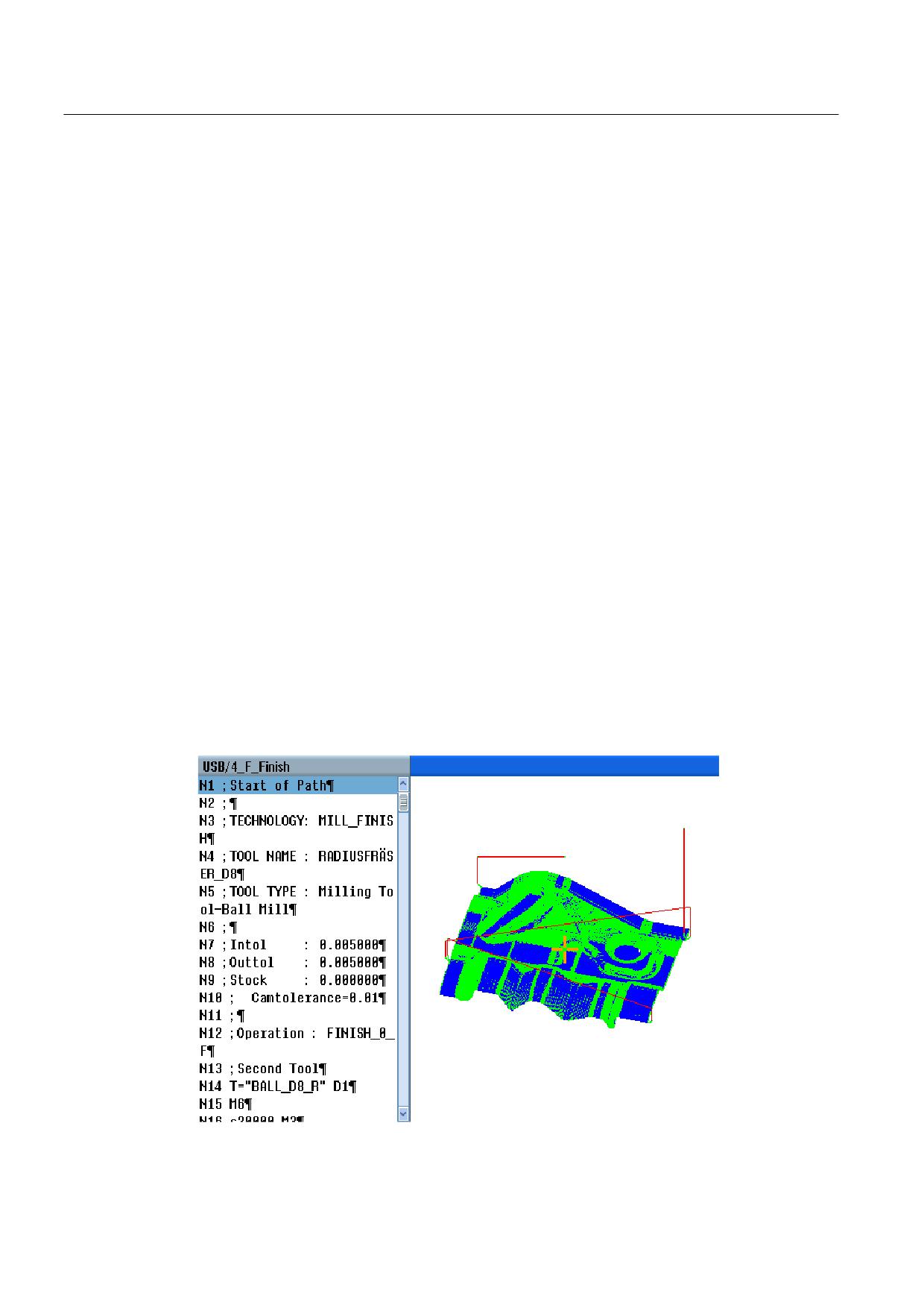
For large mold making programs, as provided by CAD systems, you have the option, using a
fast view, to display the machining paths. This allows you to obtain a fast overview of the
program and possibly correct it.
Checking the program
For instance, you can check whether
● The programmed workpiece has the correct form (shape)
● Whether there are large traversing errors
● If yes, which block must be corrected
● How the approach and retraction are performed
Simultaneous view of the program and mold making view
In the editor, next to the program block display, switch-in the graphic view.
At the left in the editor, if you set the cursor to an NC block with position data, then this NC
block is selected in the graphic view.
If you select a point to the right in the graphic view - then the NC block is selected in the left-
hand part of the editor - i.e. in the other direction. This is how you jump directly to a position
in the program in order to edit a program block for example.
Universal
142
Operating Manual, 03/2013, 6FC5398-6AP40-3BA1
Machining the workpiece
4.16 Mold making view
NC blocks that can be interpreted
Following NC blocks are supported for the mold building view.
●
Types
- Lines
G0, G1 with X Y Z
- Circles
G2, G3 with center point I, J, K or radius CR, depending on the working plane G17,
G18, G19, CIP with circular point I1, J1, K1 or radius CR
- Polynomial
POLY with X, Y, Z or PO[X] PO[Y] PO[Z]
- B-splines
BSPLINE with degree SD (SD < 6) node PL weights PW
- Absolute data AC and incremental data IC are possible
- For G2, G3 and different radii at the start and end, an Archimedes spiral is used
●
Orientation
- Rotary axis programming with ORIAXES or ORIVECT using ABC for G0, G1, G2, G3,
CIP, POLY
- Rotary axis programming with ORIAXES or ORIVECT using PO[A] POS[b] PO[C] for
POLY
- Orientation vector programming with ORIVECT using A3, B3, C3 for G0, G1, G2, G3,
CIP
- Orientation curve with ORICURVE using XH, YH, ZH, for G0, G1, G2, G3, CIP, POLY,
BSPLINE
- Orientation curve with ORICURVE using PO[XH] PO[YH] PO[ZH] for POLY
- Rotary axes can be specified using DC
●
G codes
- Working planes (for circle definition G2, G3): G17 G18 G19
- Incremental or absolute data: G90 G91
Following NC blocks are not supported for the mold making view.
● Helix programming
● Rational polynomials
● Other G codes or language commands
All blocks that cannot be interpreted are simply ignored
Universal
Operating Manual, 03/2013, 6FC5398-6AP40-3BA1
143
Machining the workpiece
4.16 Mold making view
Changing and adapting the mold making view
Just the same as for simulation and simultaneous recording, you have the option of changing
and adapting the simulation graphical representation in order to achieve the optimum view.
● Increasing or reducing the size of the graphic
● Moving the graphic
● Rotating the graphic
● Changing the section
4.16.2
Starting the mold making view
Procedure
1.
Select the "Program manager" operating area.
2.
Select the desired storage location and position the cursor on the
program that you would like to display in the mold making view.
3.
Press the "Open" softkey.
The program is opened in the editor.
4.
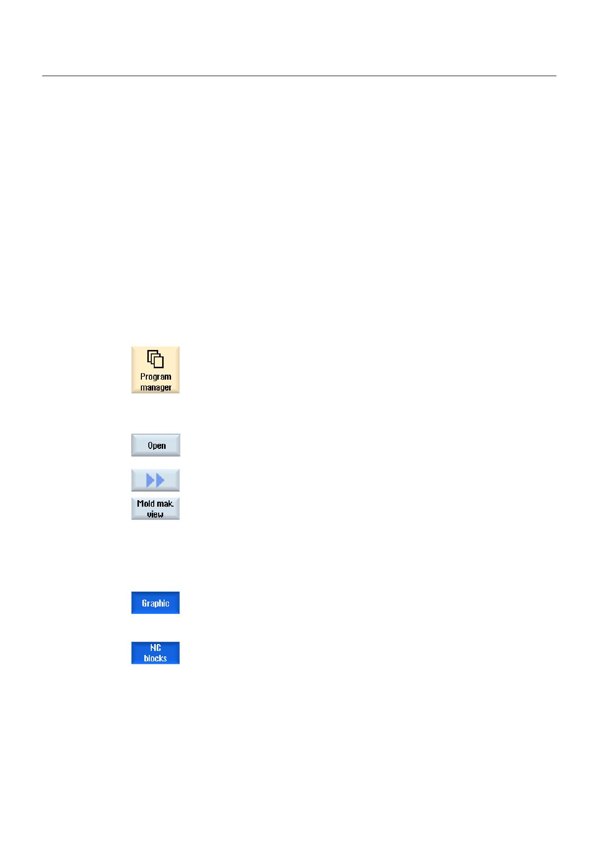
Press the ">>" and "Mold making view" softkeys.
The editor splits up into two areas.
The G code blocks are displayed in the left half of the editor.
The workpiece graphic is displayed in the right half of the editor.
All of the points and paths programmed in the part program are shown
in the graphical representation.
5.
Press the "Graphic" softkey in order to hide the graphic and to view the
program as usual in the editor
- OR -
Press the "NC blocks" softkey in order to hide the G code blocks and
therefore only to display the graphic.
Universal
144
Operating Manual, 03/2013, 6FC5398-6AP40-3BA1
Machining the workpiece
4.16 Mold making view
4.16.3
Specifically jump to the program block
If you notice anything peculiar in the graphic or identify an error, then from this location, you
can directly jump to the program block involved to possibly edit the program.
Preconditions
● The required program is opened in the mold making view.
● The "Graphic" softkey is active.
Procedure
1.
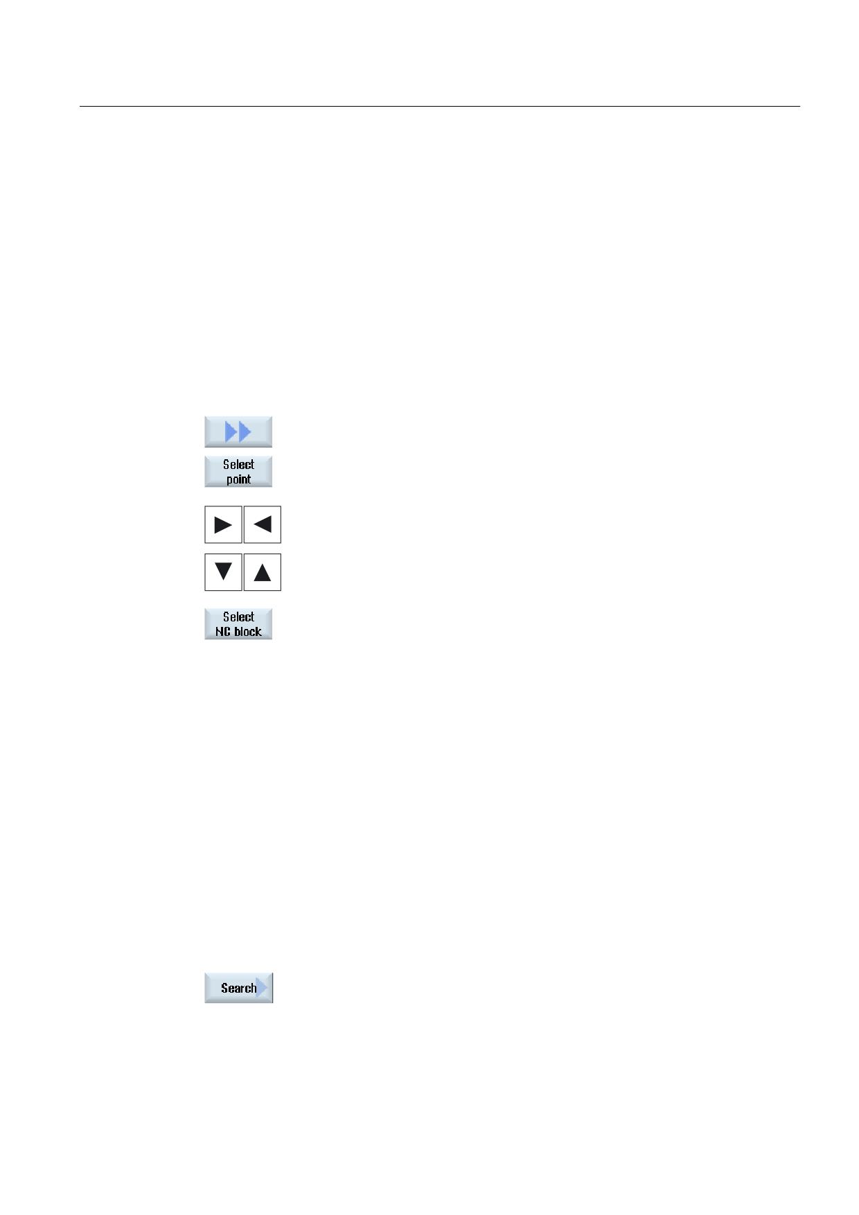
Press the ">>" and "Select point" softkeys.
Cross-hairs for selecting a point is shown in the diagram.
2.
Using the cursor keys, move the cross-hairs to the appropriate position
in the graphic.
3.
Press the "Select NC block" softkey.
The cursor jumps to the associated program block in the editor.
4.16.4
Searching for program blocks
Using the "Search" function, you can search for specific program blocks as well as edit
programs; you can do this in one step by replacing the text that you are searching for by a
new text.
Precondition
● The required program is opened in the mold making view.
● The "NC blocks" softkey is active.
Procedure
1.
Press the "Search" softkey.
A new vertical softkey bar appears.
Universal
Operating Manual, 03/2013, 6FC5398-6AP40-3BA1
145
Machining the workpiece
4.16 Mold making view
See also
Searching in programs (Page 114)
Replacing program text (Page 115)
4.16.5
Changing the view
4.16.5.1
Enlarging or reducing the graphical representation
Precondition
● The mold making view has been started.
● The "Graphic" softkey is active.
Procedure
1.
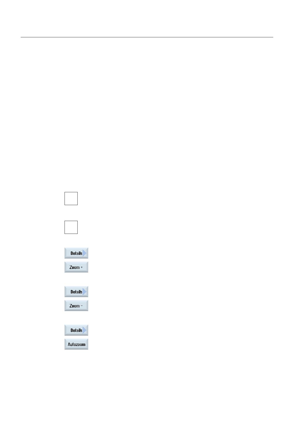
Press the <+> and <-> keys if you wish to enlarge or reduce the graphic
display.
The graphic display enlarged or reduced from the center.
- OR -
Press the "Details" and "Zoom +" softkeys if you wish to increase the
size of the segment.
- OR -
Press the "Details" and "Zoom -" softkeys if you wish to decrease the
size of the segment.
- OR -
Press the "Details" and "Auto zoom" softkeys if you wish to
automatically adapt the segment to the size of the window.
The automatic scaling function "Fit to size" takes account of the largest
expansion of the workpiece in the individual axes.
Universal
146
Operating Manual, 03/2013, 6FC5398-6AP40-3BA1
Machining the workpiece
4.16 Mold making view
Note
Selected section
The selected sections and size changes are kept as long as the program is selected.
4.16.5.2
Modifying the viewport
Use the magnifying glass if you would like to move, increase or reduce the size of the
section of the mold making view, e.g. to view details or display the complete workpiece.
Using the magnifying glass, you can define your own segment and then increase or
decrease its size.
Precondition
● The mold making view has been started.
● The "Graphic" softkey is active.
Procedure
1.
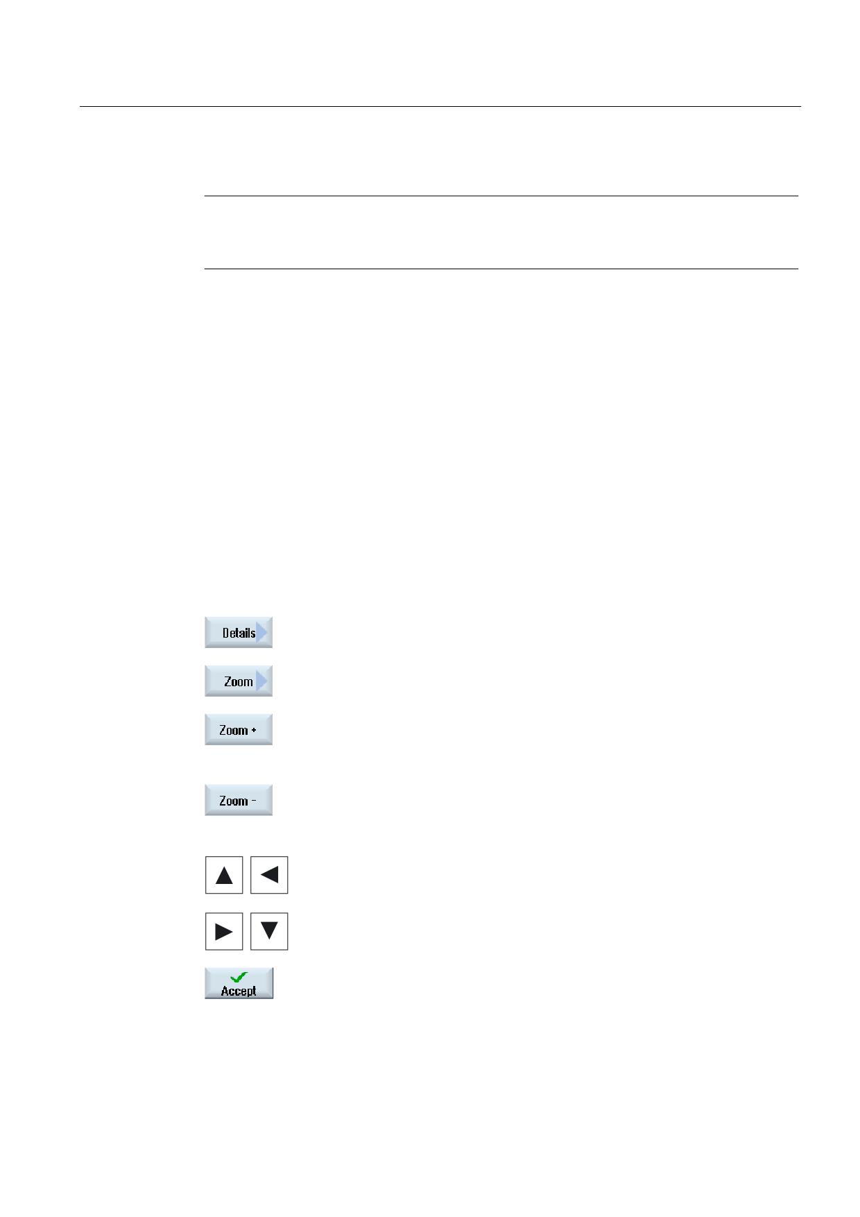
Press the "Details" softkey.
2.
Press the "Zoom" softkey.
A magnifying glass in the shape of a rectangular frame appears.
3.
Press the "Magnify +" or <+> softkey to enlarge the frame.
- OR -
Press the "Magnify -" or <-> softkey to reduce the frame.
- OR -
Press one of the cursor keys to move the frame up, down, left or right.
4.
Press the "Accept" softkey to accept the section.
Universal
Operating Manual, 03/2013, 6FC5398-6AP40-3BA1
147
Machining the workpiece
4.16 Mold making view
Universal
148
Operating Manual, 03/2013, 6FC5398-6AP40-3BA1
Simulating machining
5
5.1
Overview
During simulation, the current program is calculated in its entirety and the result displayed in
graphic form. The result of programming is verified without traversing the machine axes.
Incorrectly programmed machining steps are detected at an early stage and incorrect
machining on the workpiece prevented.
Graphic display
The simulation represented on the screen uses the correct workpiece and tool proportions.
For simulation at milling machines, the workpiece is located, fixed in space. Only the tool
moves, independent of the machine type.
Definition of blank
The blank dimensions that are entered in the program editor are used for the workpiece.
The blank is clamped with reference to the coordinate system, which is valid at the time that
the blank was defined. This means that before defining the blank in G code programs, the
required output conditions must be established, e.g. by selecting a suitable zero offset.
Programming a blank (example)
G54 G17 G90
CYCLE800(0,"TISCH", 100000,57,0,0,0,0,0,0,0,0,0,-1,100,1)
WORKPIECE(,,,"Box",112,0,-50,-80,00,155,100)
T="NC-SPOTDRILL_D16
Note
Blank offset for a changed zero offset
The blank is always created in the zero offset which is presently active.
If you select another zero offset, then the coordinate system is converted, however, the
display of the blank is not changed.
Display of the traversing paths
The traversing paths are displayed in color. Rapid traverse is red and the feedrate is green.
Depth display
The depth infeed is color-coded. The depth display indicates the actual depth at which
machining is currently taking place. The following applies to the color-coded depth display:
"The deeper, the darker".
Universal
Operating Manual, 03/2013, 6FC5398-6AP40-3BA1
149
Simulating machining
5.1 Overview
Machine references
The simulation is implemented as workpiece simulation. This means that it is not assumed
that the zero offset has already been precisely scratched or is known.
In spite of this, unavoidable machine references are in the programming, such as for
example, the tool change point in the machine, the retraction position when swiveling and
the table components of a swivel kinematic. Depending on the actual zero offset - in the
worst case - these machine references can mean that collisions are shown in the simulation
that would not occur for a realistic zero offset - or vice versa, collisions are not shown, which
could occur for a realistic zero offset.
Programmable frames
All frames and zero offsets are taken into account in the simulation.
Note
Manually swiveled axes
Note that swivel movement in simulation and during simultaneous recording is also displayed
when the axes are swiveled manually at the start.
Simulation display
You can choose one of the following types of display:
● Material removal simulation
During simulation or simultaneous recording you can follow stock removal from the
defined blank.
● Path display
You have the option of including the display of the path. The programmed tool path is
displayed.
Note
Tool display in the simulation and for simultaneous recording
In order that workpiece simulation is also possible for tools that have either not been
measured or have been incompletely entered, certain assumptions are made regarding
the tool geometry.
For instance, the length of a miller or drill is set to a value proportional to the tool radius
so that cutting can be simulated.
Note
Thread turns not displayed
For thread and drill thread milling, the thread turns are not displayed in the simulation and for
simultaneous recording.
Universal
150
Operating Manual, 03/2013, 6FC5398-6AP40-3BA1
Simulating machining
5.1 Overview
Display variants
You can choose between three variants of graphical display:
● Simulation before machining of the workpiece
Before machining the workpiece on the machine, you can perform a quick run-through in
order to graphically display how the program will be executed.
● Simultaneous recording before machining of the workpiece
Before machining the workpiece on the machine, you can graphically display how the
program will be executed during the program test and dry run feedrate. The machine
axes do not move if you have selected "no axis motion".
● Simultaneous recording during machining of the workpiece
You can follow machining of the workpiece on the screen while the program is being
executed on the machine.
Views
The following views are available for all three variants:
● Top view
● 3D view
● Side views
Status display
The current axis coordinates, the override, the current tool with cutting edge, the current
program block, the feedrate and the machining time are displayed.
In all views, a clock is displayed during graphical processing. The machining time is
displayed in hours, minutes and seconds. It is approximately equal to the time that the
program requires for processing including the tool change.
Software options
You require the option "3D simulation of the finished part" for the 3D view.
You require the option "Simultaneous recording (real-time simulation)" for the
"Simultaneous recording" function.
Determining the program runtime
The program runtime is determined when executing the simulation. The program runtime is
temporarily displayed in the editor at the end of the program.
Universal
Operating Manual, 03/2013, 6FC5398-6AP40-3BA1
151
Simulating machining
5.1 Overview
Properties of simultaneous recording and simulation
Traversing paths
For the simulation, the displayed traversing paths are saved in a ring buffer. If this buffer is
full, then the oldest traversing path is deleted with each new traversing path.
Optimum display
If simultaneous machining is stopped or has been completed, then the display is again
converted into a high-resolution screen. In some cases this is not possible. In this case, the
following message is output: "High-resolution image cannot be generated".
Working zone limitation
No working zone limits and software limit switches are effective in the tool simulation.
Start position for simulation and simultaneous recording
During simulation, the start position is converted via the zero offset to the workpiece
coordinate system.
The simultaneous recording starts at the position at which the machine is currently located.
Restrictions
● Traori: 5-axis motion is linearly interpolated. More complex motion cannot be displayed.
● Referencing: G74 from a program run does not function.
● Alarm 15110 "REORG block not possible" is not displayed.
● Compile cycles are only partly supported.
● No PLC support.
● Axis containers are not supported.
Supplementary conditions
● All of the existing data records (Toolcarrier / TRAORI, TRACYL) are evaluated and must
be correctly commissioned for correct simulation.
● Transformations with swiveled linear axis (TRAORI 64 - 69) as well as OEM
transformations (TRAORI 4096 - 4098) are not supported.
● Changes to the toolcarrier or transformation data only become effective after Power On.
● Transformation change and swivel data record change are supported. However, a real
kinematic change is not supported, where a swivel head is physically changed.
● The simulation of mold making programs with extremely short block change times can
take longer than machining, as the computation time distribution for this application is
dimensioned in favor of the machining and to the detriment of simulation.
Universal
152
Operating Manual, 03/2013, 6FC5398-6AP40-3BA1
Simulating machining
5.1 Overview
Examples
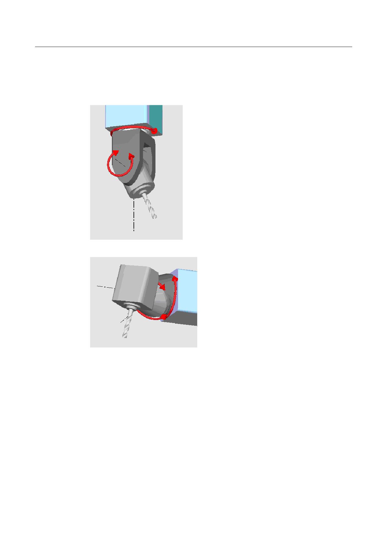
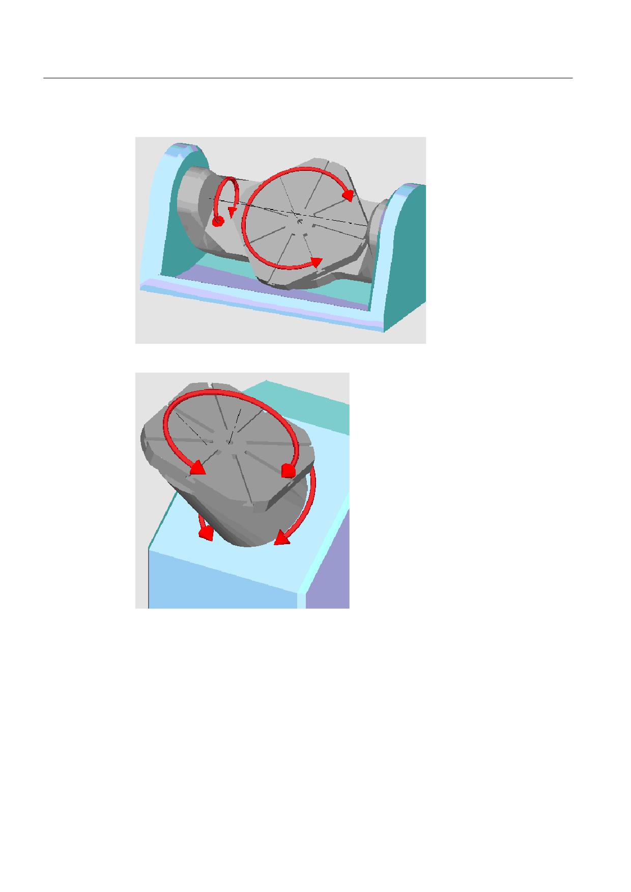
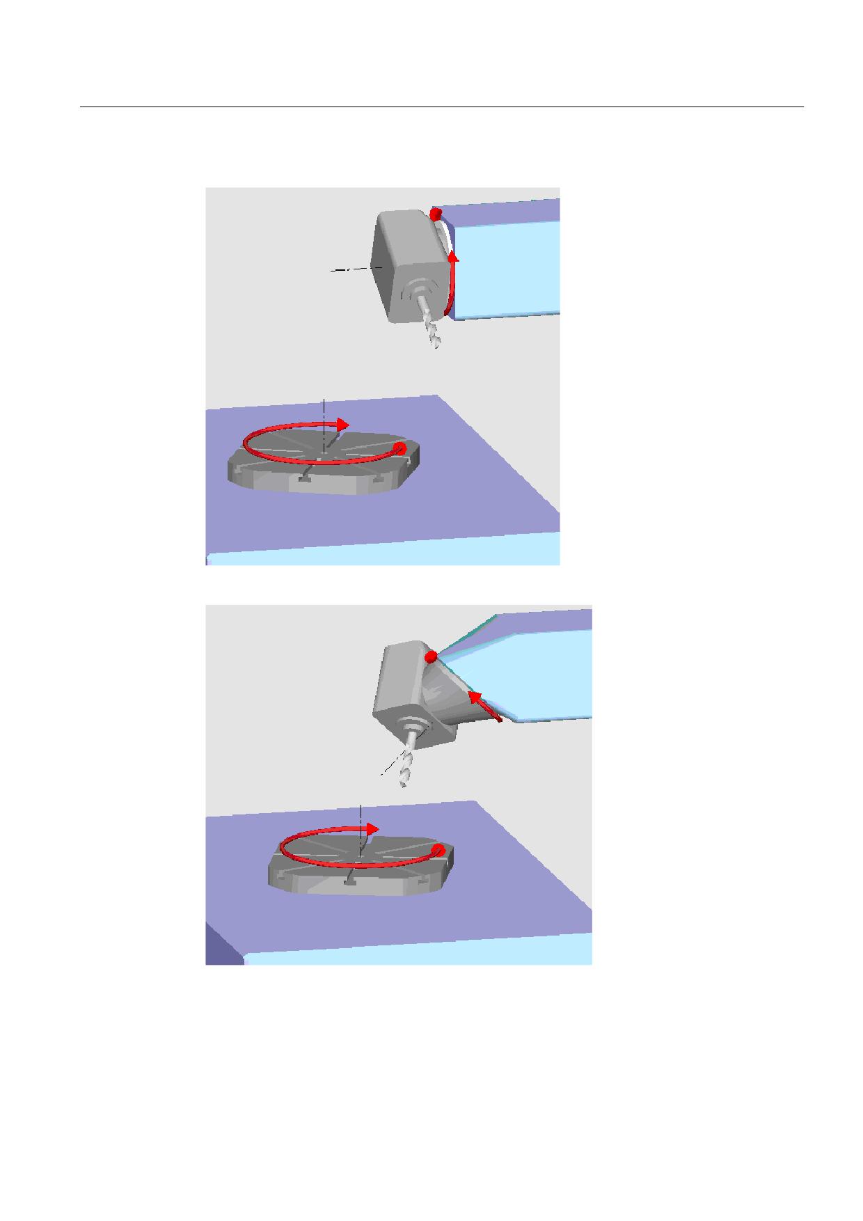
Several examples for machine types that are supported:
Swivel head 90°/90°
Swivel head 90°/45°
Universal
Operating Manual, 03/2013, 6FC5398-6AP40-3BA1
153
Simulating machining
5.1 Overview
Swivel table 90°/90°
Swivel table 90°/45°
Universal
154
Operating Manual, 03/2013, 6FC5398-6AP40-3BA1
Simulating machining
5.1 Overview
Swivel combination 90°/90°
Swivel combination 45°/90°
Universal
Operating Manual, 03/2013, 6FC5398-6AP40-3BA1
155
Simulating machining
5.2 Simulation prior to machining of the workpiece
5.2
Simulation prior to machining of the workpiece
Before machining the workpiece on the machine, you have the option of performing a quick
run-through in order to graphically display how the program will be executed. This provides a
simple way of checking the result of the programming.
Feedrate override
Feedrate override is also active during simulation.
You can change the feedrate during the simulation via the user interface.
0 %: The simulation stops.
100 %: The program is executed as quickly as possible.
See also
Changing the feedrate (Page 162)
Simulating the program block by block (Page 163)
Procedure
1.
Select the "Program Manager" operating area.
2.
Select the storage location and position the cursor on the program to be
simulated.
3.
Press the <INPUT> or <Cursor right> key.
- OR -
Double-click the program.
The selected program is opened in the "Program" operating area.
4.
Press the "Simulation" softkey.
The program execution is displayed graphically on the screen. The
machine axes do not move.
5.
Press the "Stop" softkey if you wish to stop the simulation.
- OR -
Universal
156
Operating Manual, 03/2013, 6FC5398-6AP40-3BA1
Simulating machining
5.3 Simultaneous recording prior to machining of the workpiece
Press the "Reset" softkey to cancel the simulation.
6.
Press the "Start" softkey to restart or continue the simulation.
Note
Operating area switchover
The simulation is exited if you switch into another operating area. If you restart the
simulation, then this starts again at the beginning of the program.
5.3
Simultaneous recording prior to machining of the workpiece
Before machining the workpiece on the machine, you can graphically display the execution
of the program on the screen to monitor the result of the programming.
Software option
You require the option "Simultaneous recording (real-time simulation)" for the
simultaneous recording.
You can replace the programmed feedrate with a dry run feedrate to influence the speed of
execution and select the program test to disable axis motion.
If you would like to view the current program blocks again instead of the graphical display,
you can switch to the program view.
Procedure
1.
Load a program in the "AUTO" mode.
2.
Press the "Prog. ctrl." softkey and activate the checkboxes "PRT no axis
movement" and "DRY run feedrate".
The program is executed without axis movement. The programmed
feedrate is replaced by a dry run feedrate.
3.
Press the "Sim. rec." softkey.
Universal
Operating Manual, 03/2013, 6FC5398-6AP40-3BA1
157
Simulating machining
5.4 Simultaneous recording during machining of the workpiece
4.
Press the <CYCLE START> key.
The program execution is displayed graphically on the screen.
5.
Press the "Sim. rec." softkey again to stop the recording.
5.4
Simultaneous recording during machining of the workpiece
If the view of the work space is blocked by coolant, for example, while the workpiece is being
machined, you can also track the program execution on the screen.
Software option
You require the option "Simultaneous recording (real-time simulation)" for the
simultaneous recording.
Procedure
1.
Load a program in the "AUTO" mode.
2.
Press the "Sim. rec." softkey.
3.
Press the <CYCLE START> key.
The machining of the workpiece is started and graphically displayed on
the screen.
4.
Press the "Sim. rec." softkey again to stop the recording.
Note
• If you switch-on simultaneous recording after the unmachined part information has
already been processed in the program, only traversing paths and tool are displayed.
• If you switch-off simultaneous recording during machining and then switch-on the function
again at a later time, then the traversing paths generated in the intermediate time will not
be displayed.
Universal
158
Operating Manual, 03/2013, 6FC5398-6AP40-3BA1
Simulating machining
5.5 Different views of the workpiece
5.5
Different views of the workpiece
In the graphical display, you can choose between different views so that you constantly have
the best view of the current workpiece machining, or in order to display details or the overall
view of the finished workpiece.
The following views are available:
● Top view
● 3D view
● Side views
5.5.1
Plan view
1.
Start the simulation.
2.
Press the "Top view" softkey.
The workpiece is shown from above in the top view.
Changing the display
You can increase or decrease the size of the simulation graphic and move it, as well as
change the segment.
See also
Enlarging or reducing the graphical representation (Page 164)
Panning a graphical representation (Page 165)
Modifying the viewport (Page 166)
5.5.2
3D view
1.
Start the simulation.
2.
Press the "Other views" and "3D view" softkeys.
Software option
You require the option "3D simulation (finished part)" for the simulation.
Universal
Operating Manual, 03/2013, 6FC5398-6AP40-3BA1
159
Simulating machining
5.5 Different views of the workpiece
Changing the display
You can increase or decrease the size of the simulation graphic, move it, turn it, or change
the segment.
Displaying and moving cutting planes
You can display and move cutting planes X, Y, and Z.
See also
Enlarging or reducing the graphical representation (Page 164)
Panning a graphical representation (Page 165)
Rotating the graphical representation (Page 165)
Modifying the viewport (Page 166)
Defining cutting planes (Page 167)
5.5.3
Side view
1.
Starting the simulation.
2.
Press the "Other views" softkey.
3.
Press the "From front" softkey if you wish to view the workpiece from
the front.
- OR -
Press the "From rear" softkey if you wish to view the workpiece from the
rear.
- OR -
Press the "From left" softkey if you wish to view the workpiece from the
left.
- OR -
Press the "From right" softkey if you wish to view the workpiece from
the right.
Changing the display
You can increase or decrease the size of the simulation graphic and move it, as well as
change the segment.
Universal
160
Operating Manual, 03/2013, 6FC5398-6AP40-3BA1
Simulating machining
5.6 Editing the simulation display
5.6
Editing the simulation display
5.6.1
Blank display
You have the option of replacing the blank defined in the program or to define a blank for
programs in which a blank definition cannot be inserted.
Note
The unmachined part can only be entered if simulation or simultaneous recording is in the
reset state.
Procedure
1.
The simulation or the simultaneous recording is started.
2.
Press the ">>" and "Blank" softkeys.
The "Blank Input" windows opens and displays the pre-assigned values.
3.
Enter the desired values for the dimensions.
4.
Press the "Accept" softkey to confirm your entries. The newly defined
workpiece is displayed.
5.6.2
Showing and hiding the tool path
The path display follows the programmed tool path of the selected program. The path is
continuously updated as a function of the tool movement. The tool paths can be shown or
hidden as required.
Procedure
1.
The simulation or the simultaneous recording is started.
2.
Press the ">>" softkey.
The tool paths are displayed in the active view.
3.
Press the softkey to hide the tool paths.
The tool paths are still generated in the backg0round and can be shown
again by pressing the softkey again.
4.
Press the "'Delete tool path" softkey.
All of the tool paths recorded up until now are deleted.
Universal
Operating Manual, 03/2013, 6FC5398-6AP40-3BA1
161
Simulating machining
5.7 Program control during simulation
5.7
Program control during simulation
5.7.1
Changing the feedrate
You can change the feedrate at any time during the simulation.
You can track the changes in the status line.
Note
If you are working with the "Simultaneous recording" function, the rotary switch (override) on
the control panel is used.
Procedure
1.
Simulation is started.
2.
Press the "Program control" softkey.
3.
Press the "Override +" or "Override -" softkey to increase or decrease
the feedrate by 5%.
- OR -
Press the "Override 100%" softkey to set the feedrate to the maximum
value.
- OR -
Press the "<<" softkey to return to the main screen and perform the
simulation with changed feedrate.
Note
Toggling between "Override +" and "Override -"
Press the <CTRL> and <Cursor down> or <Cursor up> keys to toggle
between the "Override +" and "Override -" softkeys.
Universal
162
Operating Manual, 03/2013, 6FC5398-6AP40-3BA1
Simulating machining
5.7 Program control during simulation
5.7.2
Simulating the program block by block
You can control the program execution during simulation, i.e. execute a program block by
block, as when executing a program.
Procedure
1.
Simulation is started.
2.
Press the "Program control" and "Single block" softkeys.
3.
Press the "Back" and "Start SBL" softkeys.
The pending block of the program is simulated and then stops.
4.
Press "Start SBL" as many times as you want to simulate a single
program block.
5.
Press the "Program control" and the "Single block" softkeys to exist the
single block mode.
Note
Enabling/disabling single block
Press the <CTRL> and <S> keys simultaneously to enable and disable
the single block mode.
+
6
Universal
Operating Manual, 03/2013, 6FC5398-6AP40-3BA1
163
Simulating machining
5.8 Modifying and adapting the simulation graphics
5.8
Modifying and adapting the simulation graphics
5.8.1
Enlarging or reducing the graphical representation
Precondition
The simulation or the simultaneous recording is started.
Procedure
1.
Press the <+> and <-> keys if you wish to enlarge or reduce the graphic
display.
The graphic display enlarged or reduced from the center.
- OR -
Press the "Details" and "Zoom +" softkeys if you wish to increase the
size of the segment.
- OR -
Press the "Details" and "Zoom -" softkeys if you wish to decrease the
size of the segment.
- OR -
Press the "Details" and "Auto zoom" softkeys if you wish to
automatically adapt the segment to the size of the window.
The automatic scaling function "Fit to size" takes account of the largest
expansion of the workpiece in the individual axes.
Note
Selected section
The selected sections and size changes are kept as long as the program is selected.
Universal
164
Operating Manual, 03/2013, 6FC5398-6AP40-3BA1
Simulating machining
5.8 Modifying and adapting the simulation graphics
5.8.2
Panning a graphical representation
Precondition
The simulation or the simultaneous recording is started.
Procedure
1.
Press a cursor key if you wish to move the graphic up, down, left, or
right.
5.8.3
Rotating the graphical representation
In the 3D view you can rotate the position of the workpiece to view it from all sides.
Precondition
Simulation has been started and the 3D view is selected.
Procedure
1.
Press the "Details" softkey.
2.
Press the "Rotate view" softkey.
2.
Press the "Arrow right", "Arrow left", "Arrow up", "Arrow down", "Arrow
clockwise" and "Arrow counterclockwise" softkeys to change the
position of the workpiece.
- OR -
Universal
Operating Manual, 03/2013, 6FC5398-6AP40-3BA1
165
Simulating machining
5.8 Modifying and adapting the simulation graphics
Keep the <Shift> key pressed and then turn the workpiece in the desired
direction using the appropriate cursor keys.
5.8.4
Modifying the viewport
If you would like to move, enlarge or decrease the size of the segment of the graphical
display, e.g. to view details or display the complete workpiece, use the magnifying glass.
Using the magnifying glass, you can define your own segment and then increase or
decrease its size.
Precondition
The simulation or the simultaneous recording is started.
Procedure
1.
Press the "Details" softkey.
2.
Press the "Magnifying glass" softkey.
A magnifying glass in the shape of a rectangular frame appears.
3.
Press the "Magnify +" or <+> softkey to enlarge the frame.
- OR -
Press the "Magnify -" or <-> softkey to reduce the frame.
- OR -
Press one of the cursor keys to move the frame up, down, left or right.
4.
Press the "Accept" softkey to accept the section.
Universal
166
Operating Manual, 03/2013, 6FC5398-6AP40-3BA1
Simulating machining
5.8 Modifying and adapting the simulation graphics
5.8.5
Defining cutting planes
In the 3D view, you have the option of "cutting" the workpiece and therefore displaying
certain views in order to show hidden contours.
Precondition
The simulation or the simultaneous recording is started.
Procedure
1.
Press the "Details" softkey.
2.
Press the "Cut" softkey.
The workpiece is displayed in the cut state.
3.
Press the corresponding softkey to shift the cutting plane in the required
direction.
…
Universal
Operating Manual, 03/2013, 6FC5398-6AP40-3BA1
167

Simulating machining
5.9 Displaying simulation alarms
5.9
Displaying simulation alarms
Alarms might occur during simulation. If an alarm occurs during a simulation run, a window
opens in the operating window to display it.
The alarm overview contains the following information:
● Date and time
● Deletion criterion
Specifies with which softkey the alarm is acknowledged
● Alarm number
● Alarm text
Precondition
Simulation is running and an alarm is active.
Procedure
1.
Press the "Program control" and "Alarm" softkeys.
The "Simulation Alarms" window is opened and a list of all pending
alarms is displayed.
Press the "Acknowledge alarm" softkey to reset the simulation alarms
indicated by the Reset or Cancel symbol.
The simulation can be continued.
- OR -
Press the "Simulation Power On" softkey to reset a simulation alarm
indicated by the Power On symbol.
Universal
168
Operating Manual, 03/2013, 6FC5398-6AP40-3BA1
Multi-channel view (only 840D sl)
6
6.1
Multi-channel view
The multi-channel view allows you to simultaneously view several channels in the following
operating areas:
● "Machine" operating area
● "Program" operating area
6.2
Multi-channel view in the "Machine" operating area
With a multi-channel machine, you have the option of simultaneously monitoring and
influencing the execution of several programs.
Machine manufacturer
Please refer to the machine manufacturer's specifications.
Displaying the channels in the "Machine" operating area
In the "Machine" operating area, you can display 2 - 4 channels simultaneously.
Using the appropriate settings, you can define the sequence in which channels are
displayed. Here, you can also select if you wish to hide a channel.
Note
The "REF POINT" operating mode is shown only in the single-channel view.
Multi-channel view
2 - 4 channels are simultaneously displayed in channel columns on the user interface.
● Two windows are displayed one above the other for each channel.
● The actual value display is always in the upper window.
● The same window is displayed for both channels in the lower window.
● You can select the display in the lower window using the vertical softkey bar.
The following exceptions apply when making a selection using the vertical softkeys:
- The "Actual values MCS" softkey switches over the coordinate systems of both
channels.
- The "Zoom actual value" and "All G functions" softkeys switch into the single-channel
view.
Universal
Operating Manual, 03/2013, 6FC5398-6AP40-3BA1
169

Multi-channel view (only 840D sl)
6.2 Multi-channel view in the "Machine" operating area
Single-channel view
If, for your multi-channel machine, you always only wish to monitor one channel, then you
can set a permanent single-channel view.
Horizontal softkeys
● Block search
When selecting the block search, the multi-channel view is kept. The block display is
displayed as search window.
● Program control
The "Program Control" window is displayed for the channels configured in the multi-
channel view. The data entered here applies for these channels together.
● If you press an additional horizontal softkey in the "Machine" operating area (e.g.
"Overstore", "Synchronized actions"), then you change into a temporary single-channel
view. If you close the window again, then you return to the multi-channel view.
Switching between single- and multi-channel view
Press the <MACHINE> key in order to briefly switch between the single-
and multi-channel view in the machine area.
Press the <NEXT WINDOW> key in order to switch between the upper
and lower window within a channel column.
Editing a program in the block display
You can perform simple editing operations as usual with the <INSERT>
key in the actual block display.
If there is not sufficient space, you switch over into the single-channel view.
Running-in a program
You select individual channels to run-in the program at the machine.
Requirement
● Several channels have been set-up.
● The setting "2 channels", "3 channels" or "4 channels" is selected.
Universal
170
Operating Manual, 03/2013, 6FC5398-6AP40-3BA1
Multi-channel view (only 840D sl)
6.2 Multi-channel view in the "Machine" operating area
Displaying/hiding a multi-channel view
1.
Select the "Machine" operating area
2.
Select the "JOG", "MDA" or "AUTO" mode.
3.
Press the menu forward key and the "Settings" softkey.
4.
Press the "Multi-channel view" softkey.
5.
In the window "Settings for Multi-Channel View" in the selection
box "View", select the required entry (e.g. "2 channels") and
define the channels as well as the sequence in which they are to
be displayed.
In the basic screen for the "AUTO", "MDA" and JOG" operating
modes, the upper window of the left-hand and right-hand channel
columns are occupied by the actual value window.
6.
Press the "T,F,S" softkey if you wish to view the "T,F,S" window.
The "T,F,S" window is displayed in the lower window of the left-
hand and right-hand channel column.
Note:
The "T,F,S" softkey is present only for smaller operator panels,
i.e. up to OP012.
Universal
Operating Manual, 03/2013, 6FC5398-6AP40-3BA1
171
Multi-channel view (only 840D sl)
6.3 Multi-channel view for large operator panels
6.3
Multi-channel view for large operator panels
On the OP015 and OP019 operator panels as well as on the PC, you have the option of
displaying up to four channels next to each one. This simplifies the creation and run-in for
multi-channel programs.
Constraints
● OP015 with a resolution of 1024x768 pixels: up to three channels visible
● OP019 with a resolution of 1280x1024 pixels: up to four channels visible
● The operation of a OP019 requires a PCU50.5
3- or 4-channel view in the "Machine" operating area
Use the multi-channel view settings to select the channels and specify the view.
Channel view
Display in the "Machine" operating area
3-channel view
The following windows are displayed one above the other for each channel:
• Actual Value window
• T,F,S window
• Block Display window
Selecting functions
• The T,F,S window is overlaid by pressing one of the vertical softkeys.
4-channel view
The following windows are displayed one above the other for each channel:
• Actual Value window
• G functions (the "G functions" softkey is omitted). "All G functions" is
accessed with the Menu forward key.
• T,S,F window
• Block Display window
Selecting functions
• The window showing the G codes is overlaid if you press one of the
vertical softkeys.
Universal
172
Operating Manual, 03/2013, 6FC5398-6AP40-3BA1
Multi-channel view (only 840D sl)
6.3 Multi-channel view for large operator panels
Toggling between the channels
Press the <CHANNEL> key to toggle between the channels.
Press the <NEXT WINDOW> key to toggle within a channel column
between the three or four windows arranged one above the other.
Note
2-channel display
Unlike the smaller operator panels, the T,F,S window is visible for a 2-channel view in the
"Machine" operating area.
Program operating area
You can display as many as ten programs next to each other in the editor.
Displaying a program
You can define the width of the program in the Editor window using the settings in the editor.
This means that you can distribute programs evenly - or you can widen the column with the
active program .
Channel status
When required, channel messages are displayed in the status display.
Machine manufacturer
Please refer to the machine manufacturer's specifications.
Universal
Operating Manual, 03/2013, 6FC5398-6AP40-3BA1
173

Multi-channel view (only 840D sl)
6.4 Setting the multi-channel view
6.4
Setting the multi-channel view
Setting
Meaning
View
Here, you specify how many channels are displayed.
•
1 channel
•
2 channels
•
3 channels
•
4 channels
Channel selection and
You specify which channels in which sequence are displayed in the multi-
sequence
channel view.
(for "2 - 4 channels"
view)
Visible
Here, you specify which channels are displayed in the multi-channel view.
You can quickly hide channels from the view.
(for "2 - 4 channels"
view)
Example
Your machine has 6 channels.
You configure channels 1 - 4 for the multi-channel view and define the display sequence
(e.g. 1,3,4,2).
In the multi-channel view, for a channel switchover, you can only switch between the
channels configured for the multi-channel view; all others are not taken into consideration.
Using the <CHANNEL> key, advance the channel in the "Machine" operating area - you
obtain the following views: Channels "1" and "3", channels "3" and "4", channels "4" and "2".
Channels "5" and "6" are not displayed in the multi-channel view.
In the single-channel view, toggle between all of the channels (1...6) without taking into
account the configured sequence for the multi-channel view.
Using the channel menu, you can always select all channels, also those not configured for
multi-channel view. If you switch to another channel, which is not configured for the multi-
channel view, then the system automatically switches into the single-channel view. There is
no automatic switchback into the multi-channel view, even if a channel is again selected,
which has been configured for multi-channel view.
Universal
174
Operating Manual, 03/2013, 6FC5398-6AP40-3BA1
Multi-channel view (only 840D sl)
6.4 Setting the multi-channel view
Procedure
1.
Select the "Machine" operating area.
2.
Select the "JOG", "MDA" or "AUTO" mode.
3.
Press the menu forward key and the "Settings" softkey.
4.
Press the "Multi-channel view" softkey.
The "Settings for Multi-Channel View" window is opened.
5.
Set the multi-channel or single-channel view and define which channels
are to be seen in the "Machine" operating area - and in the editor - in
which sequence.
Universal
Operating Manual, 03/2013, 6FC5398-6AP40-3BA1
175
Multi-channel view (only 840D sl)
6.4 Setting the multi-channel view
Universal
176
Operating Manual, 03/2013, 6FC5398-6AP40-3BA1
Collision avoidance (only 840D sl)
7
7.1
Collision monitoring in the machine operator area
With the aid of collision avoidance, you can avoid collisions and therefore major damage
during the machining of a workpiece or when creating programs.
Software option
You require the "Collision avoidance (machine, working area)" software option in
order to use this function.
Machine manufacturer
Please refer to the machine manufacturer's specifications.
Collision avoidance is based on a machine model. The kinematics of the machine are
described as a kinematic chain. For machine parts, which are to be protected, protection
areas are attached to these chains. The geometry of the protection areas is defined using
protection area elements. The control then knows how they move in the machine coordinate
system depending on the position of the machine axes. You then subsequently define the
collision pairs, i.e. two protection areas, which are monitored with respect to one another.
The "Collision avoidance" function regularly calculates the clearance from these protection
areas. When two protection areas approach one another, and a specific safety clearance is
reached, an alarm is displayed and before the corresponding traversing block, the program
is stopped and/or the traversing motion is stopped.
References
More detailed explanations on the collision avoidance can be found in the following
reference:
SINUMERIK Operate (IM9) / SINUMERIK 840D sl Commissioning Manual;
Function Manual, Special Functions (FB3):
● Section: "Kinematic chain (K7)"
● Section: "Geometric machine modeling (K8)"
● Section: "Collision avoidance (K9)"
● Section: "NC/PLC interface signals (Z3)" > "Collision avoidance (K9)"
Universal
Operating Manual, 03/2013, 6FC5398-6AP40-3BA1
177
Collision avoidance (only 840D sl)
7.2 Switching the collision avoidance on and off
Precondition
● Collision avoidance is setup and an active machine model is available.
● In the "Collision avoidance" setting, for the AUTO mode, collision avoidance is selected.
Procedure
1.
Select the "Machine" operating area
2.
Press the <AUTO> key.
3.
Press the "Sim. rec." softkey.
4.
Press the "Other views" and "Machine area" softkeys.
An active machine model is displayed for simultaneous recording.
7.2
Switching the collision avoidance on and off
Using "Settings", you have the option of separately activating or deactivating the collision
monitoring for the Machine operating area (operating modes, AUTO, JOG and MDI)
separately for the machine and tools.
Using machine data, you define from which protection level the collision monitoring for the
machine or the tool can be activated or deactivated in the operating modes JOG/MDI or
AUTO.
Machine manufacturer
Please refer to the machine manufacturer's specifications.
Setting
Effect
JOG/MDI operating mode
They switch the collision monitoring for the operating modes JOG/MDI
completely on or off.
Collision avoidance
AUTO mode
They switch the collision monitoring for the operating mode AUTO
completely on or off.
Collision avoidance
Universal
178
Operating Manual, 03/2013, 6FC5398-6AP40-3BA1
Collision avoidance (only 840D sl)
7.2 Switching the collision avoidance on and off
Setting
Effect
JOG/MDI
If the collision monitoring for the JOG/MDI operating modes is
activated, then as a minimum, the
Machine
machine protection areas are monitored.
The parameter cannot be changed.
AUTO
If the collision monitoring for the AUTO operating mode is activated,
then as a minimum, the
Machine
machine protection areas are monitored.
The parameter cannot be changed.
JOG/MDI
They switch the collision monitoring of the tool protection areas for the
operating modes JOG/MDI on or off.
Tools
AUTO
They switch the collision monitoring of the tool protection areas for the
operating mode AUTO on or off.
Tools
Procedure
1.
Select the "Machine" operating area.
2.
Select the "JOG", "MDI" or "AUTO" mode.
3.
Press the menu forward key and the "Settings" softkey.
4.
Press the "Collision avoidance" softkey.
The "Collision Avoidance" window opens.
5.
In the "Collision avoidance" line for the required operating modes (e.g.
for JOG/MDI), select the entry "On" to activate the collision avoidance
or "Off" to deactivate collision avoidance.
6.
Deactivate the "Tools" checkbox if you only want to monitor the
machine protection areas.
Universal
Operating Manual, 03/2013, 6FC5398-6AP40-3BA1
179
Collision avoidance (only 840D sl)
7.2 Switching the collision avoidance on and off
Universal
180
Operating Manual, 03/2013, 6FC5398-6AP40-3BA1
Tool management
8
8.1
Lists for the tool management
All tools and also all magazine locations that have been created or configured in the NC are
displayed in the lists in the Tool area.
All lists display the same tools in the same order. When switching between the lists, the
cursor remains on the same tool in the same screen segment.
The lists have different parameters and softkey assignments. Switching between lists is a
specific change from one topic to the next.
● Tool list
All parameters and functions required to create and set up tools are displayed.
● Tool wear
All parameters and functions that are required during operation, e.g. wear and monitoring
functions, are listed here.
● Magazine
You will find the magazine and magazine location-related parameters and functions for
the tools / magazine locations here.
● Tool data OEM
This list can be freely defined by the OEM.
Grinding-specific tool data is provided here if you are working with
grinding tools.
Sorting the lists
You can change the sorting within the lists according to:
● The magazine
● The name (tool identifier, alphabetic)
● The tool type
● The T number (tool identifier, numerical)
● The D number
Universal
Operating Manual, 03/2013, 6FC5398-6AP40-3BA1
181
Tool management
8.2 Magazine management
Filtering the lists
You can filter the lists according to the following criteria:
● Only display the first cutting edge
● Only tools that are ready to use
● Only tools that have reached the pre-alarm limit
● Only locked tools
● Only tools with active code
Search functions
You have the option of searching through the lists according to the following objects:
● Tool
● Magazine location
● Empty location
8.2
Magazine management
Depending on the configuration, the tool lists support a magazine management.
Magazine management functions
● Press the "Magazine" horizontal softkey to obtain a list that displays tools with magazine-
related data.
● The Magazine / Magazine location column is displayed in the lists.
● In the default setting, the lists are displayed sorted according to magazine location.
● The magazine selected via the cursor is displayed in the title line of each list.
● The "Magazine selection" vertical softkey is displayed in the tool list.
● You can load and unload tools to and from a magazine via the tool list.
Machine manufacturer
Please refer to the machine manufacturer's specifications.
Universal
182
Operating Manual, 03/2013, 6FC5398-6AP40-3BA1
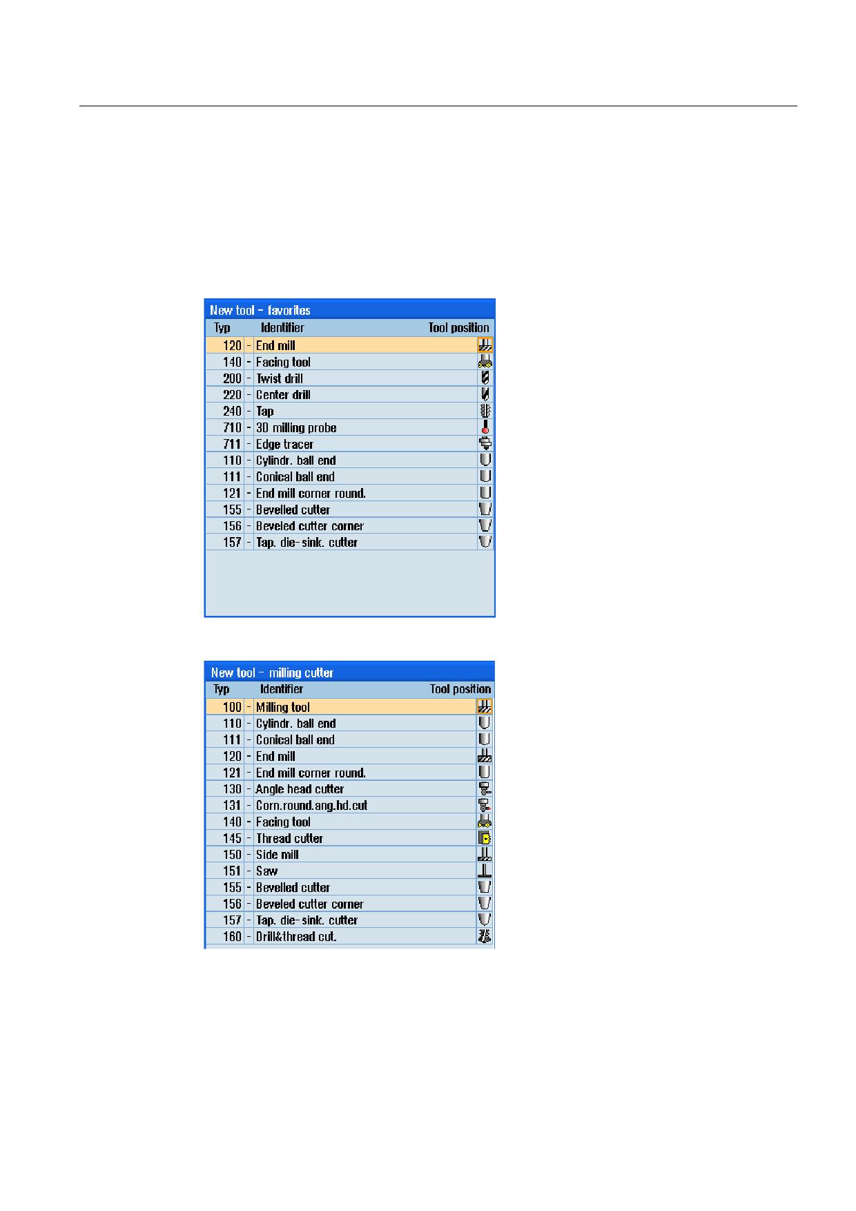
Tool management
8.3 Tool types
8.3
Tool types
A number of tool types are available when you create a new tool. The tool type determines
which geometry data is required and how it will be computed.
Tool types
Figure 8-1
Example of Favorites list
Figure 8-2
Available tools in the "New Tool - Milling Cutter" window
Universal
Operating Manual, 03/2013, 6FC5398-6AP40-3BA1
183
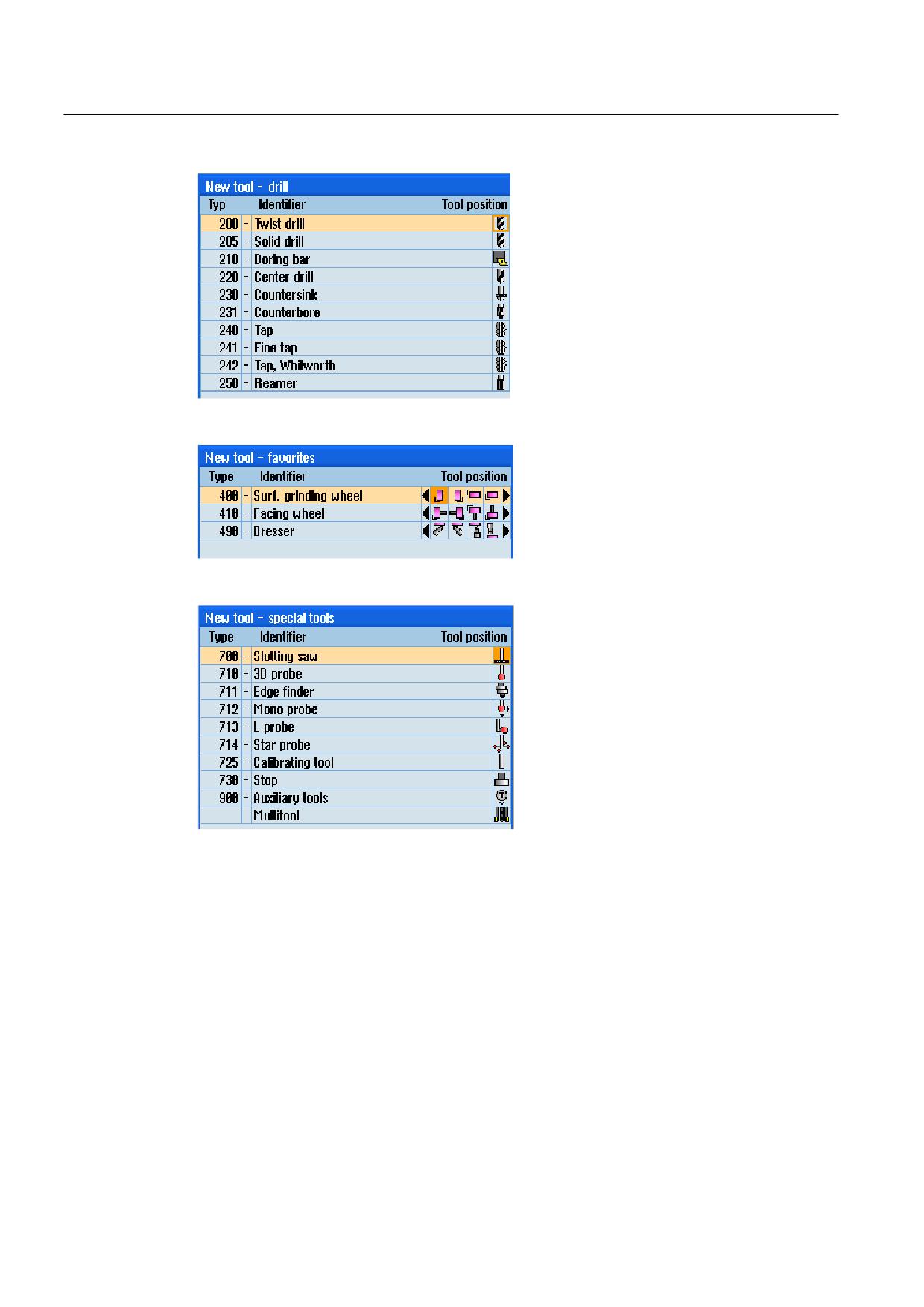
Tool management
8.3 Tool types
Figure 8-3
Available tools in the "New Tool - Drill" window
Figure 8-4
Tools listed in the "New Tool - Grinding Tools" window
Figure 8-5
Available tools in the "New Tool - Special Tools" window
Universal
184
Operating Manual, 03/2013, 6FC5398-6AP40-3BA1
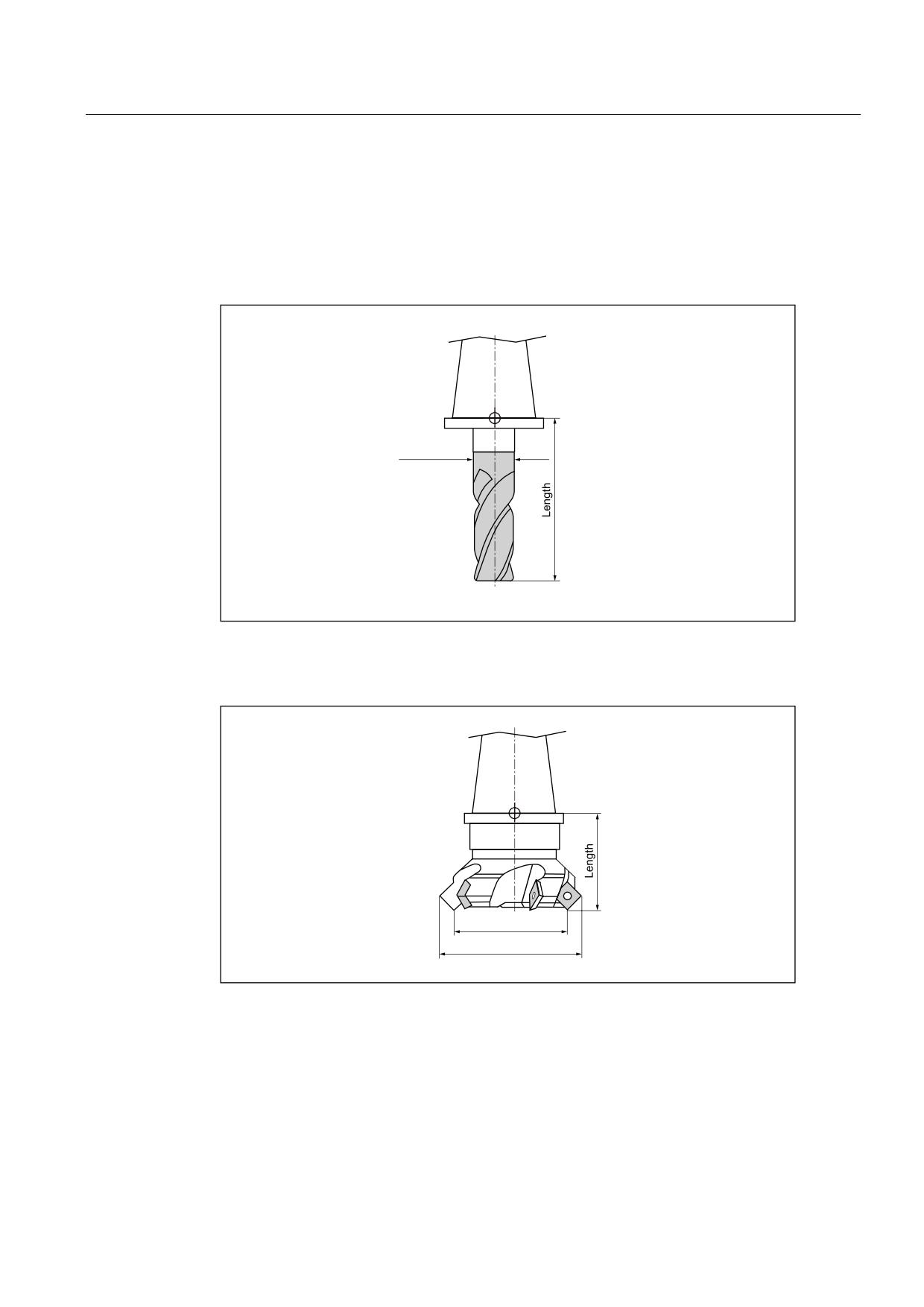
Tool management
8.4 Tool dimensioning
8.4
Tool dimensioning
This section provides an overview of the dimensioning of tools.
Tool types
'LDPHWHU
Figure 8-6
End mill (Type 120)
'LDPHWHU
2XWHU GLDPHWHU
Figure 8-7
Face mill (Type 140)
Universal
Operating Manual, 03/2013, 6FC5398-6AP40-3BA1
185
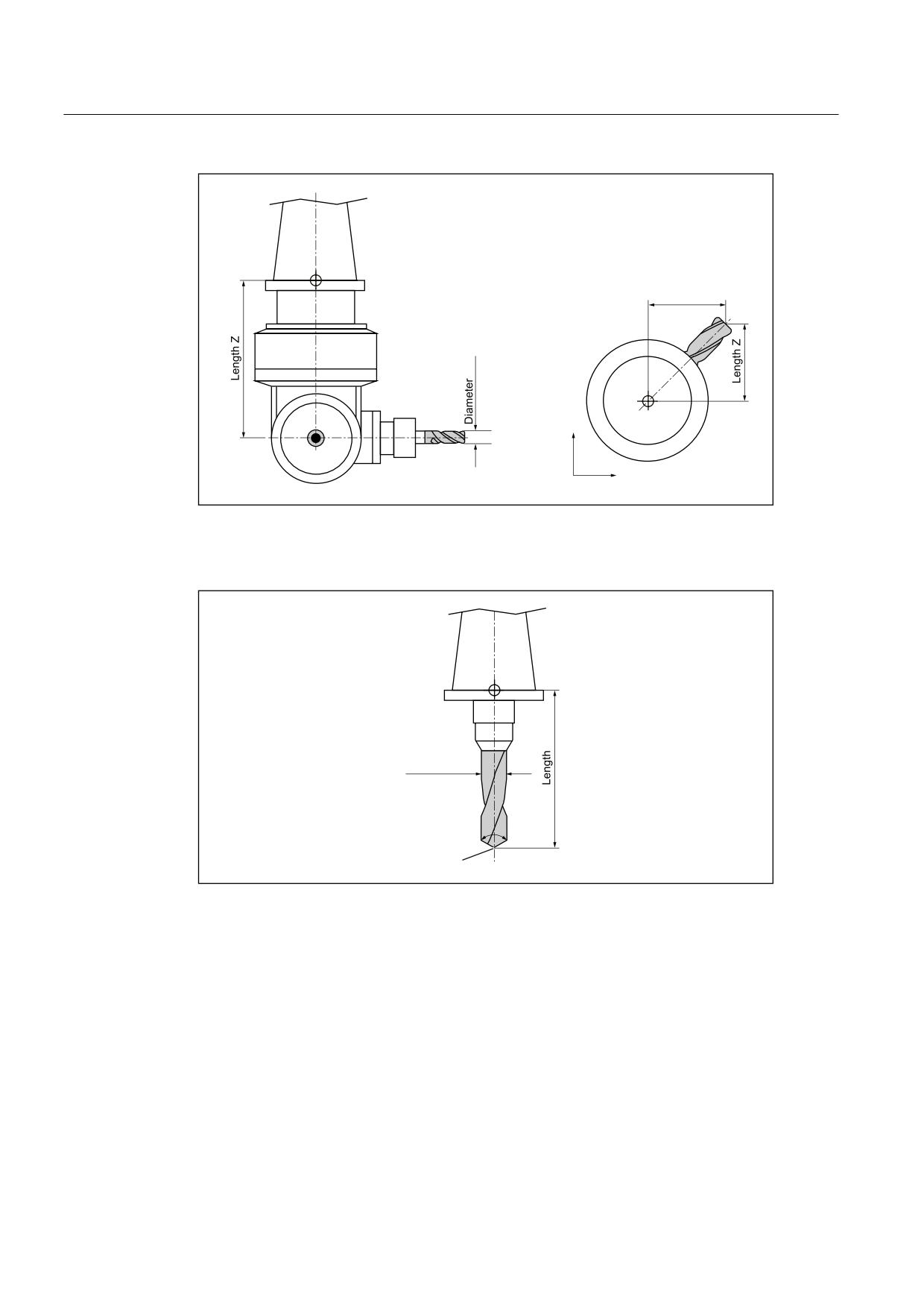
Tool management
8.4 Tool dimensioning
/HQJWK ;
<
;
Figure 8-8
Angle head cutter (Type 130)
'LDPHWHU
7LS DQJOH
Figure 8-9
Drill (Type 200)
Universal
186
Operating Manual, 03/2013, 6FC5398-6AP40-3BA1
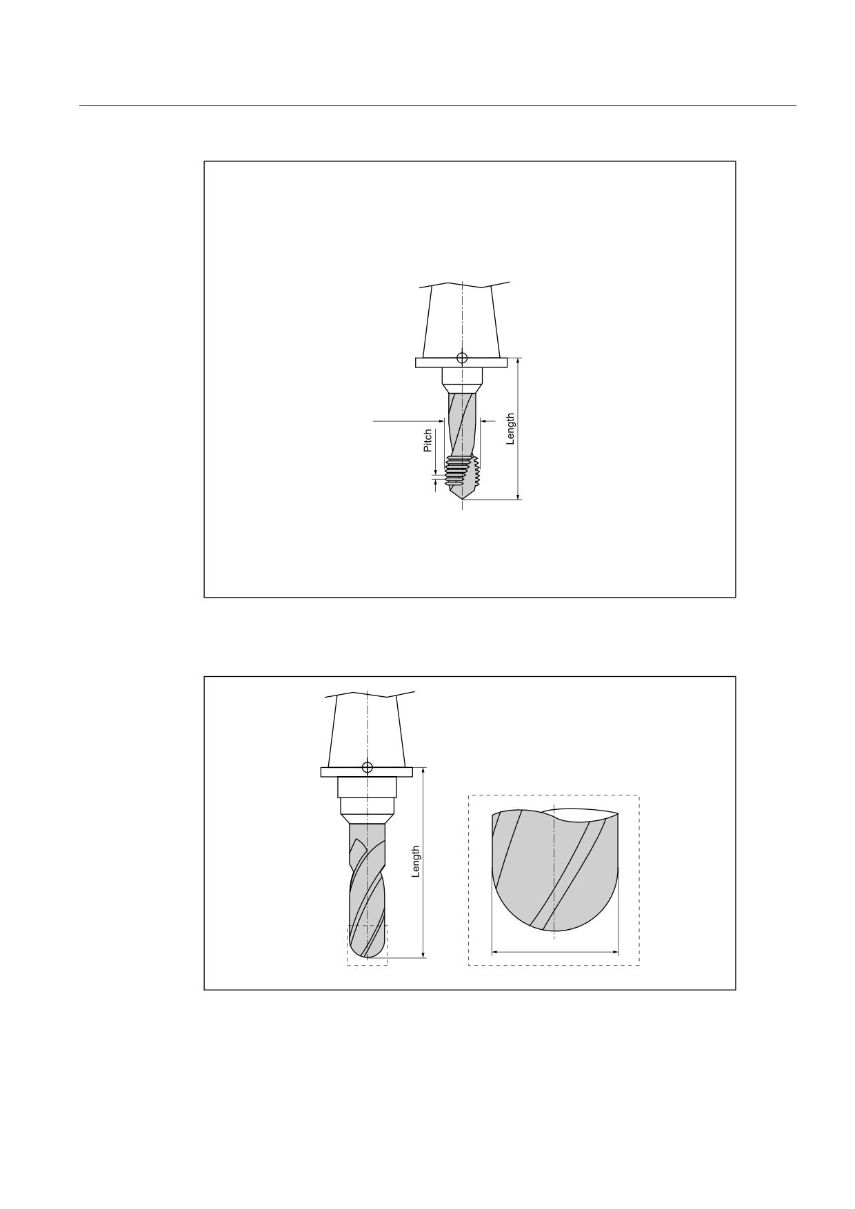
Tool management
8.4 Tool dimensioning
'LDPHWHU
Figure 8-10 Tap (Type 240)
'LDPHWHU
Figure 8-11 3D tool with an example of a cylindrical die-sinking cutter (Type 110)
Universal
Operating Manual, 03/2013, 6FC5398-6AP40-3BA1
187
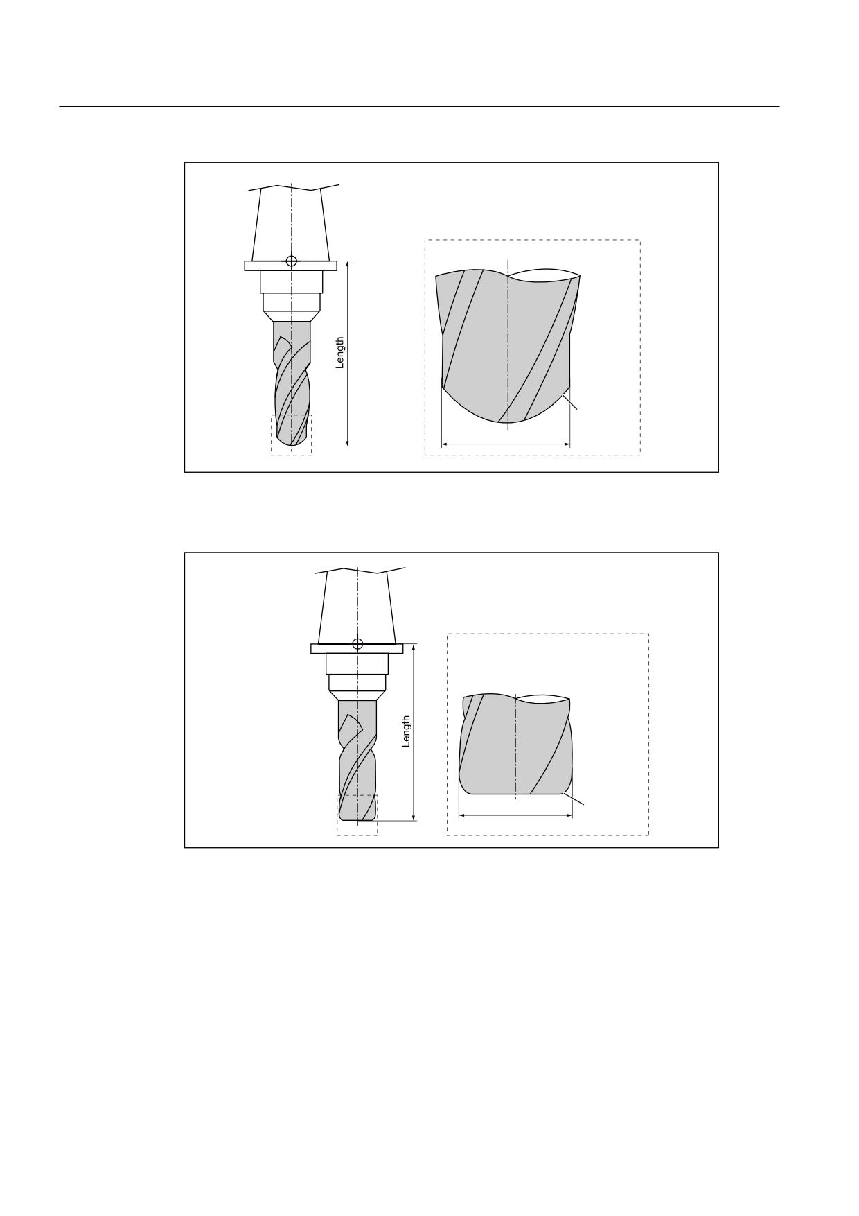
Tool management
8.4 Tool dimensioning
&RUQHU UDGLXV
'LDPHWHU
Figure 8-12 3D tool type with an example of a ballhead cutter (Type 111)
'LDPHWHU
&RUQHU UDGLXV
Figure 8-13 3D tool with an example of an end mill with corner rounding (Type 121)
Universal
188
Operating Manual, 03/2013, 6FC5398-6AP40-3BA1
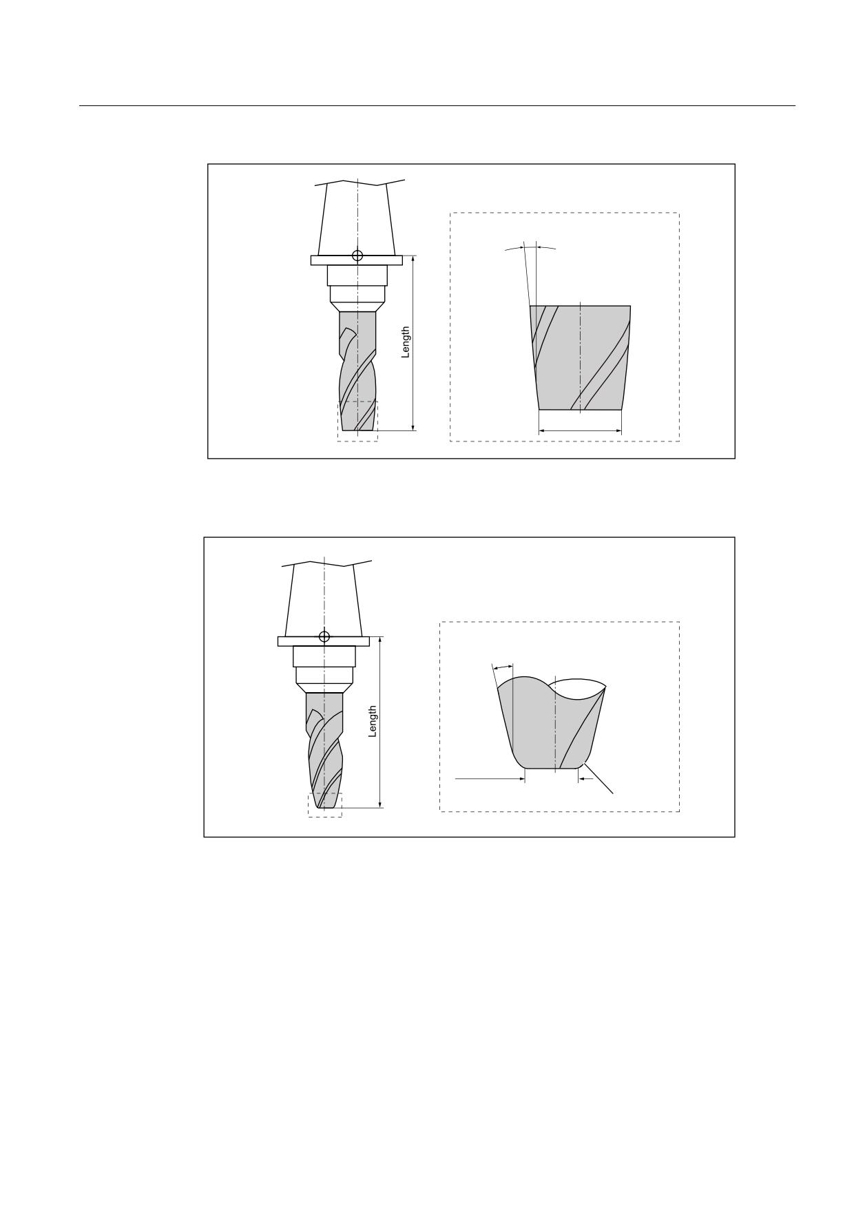
Tool management
8.4 Tool dimensioning
$QJOH IRU FRQLFDO
WRROV
'LDPHWHU
Figure 8-14 3D tool type with an example of a bevel cutter (Type 155)
$QJOH IRU FRQLFDO WRROV
'LDPHWHU
&RUQHU UDGLXV
Figure 8-15 3D tool with an example of a bevel cutter with corner rounding (Type 156)
Universal
Operating Manual, 03/2013, 6FC5398-6AP40-3BA1
189
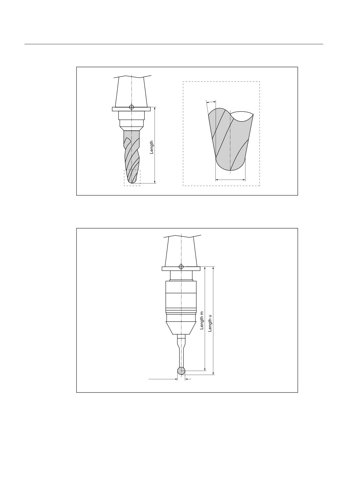
Tool management
8.4 Tool dimensioning
$QJOH IRU FRQLFDO WRROV
'LDPHWHU
Figure 8-16 3D tool with an example of a tapered die-sinking cutter (Type 157)
'LDPHWHU
Figure 8-17 Electronic workpiece probe
Universal
190
Operating Manual, 03/2013, 6FC5398-6AP40-3BA1
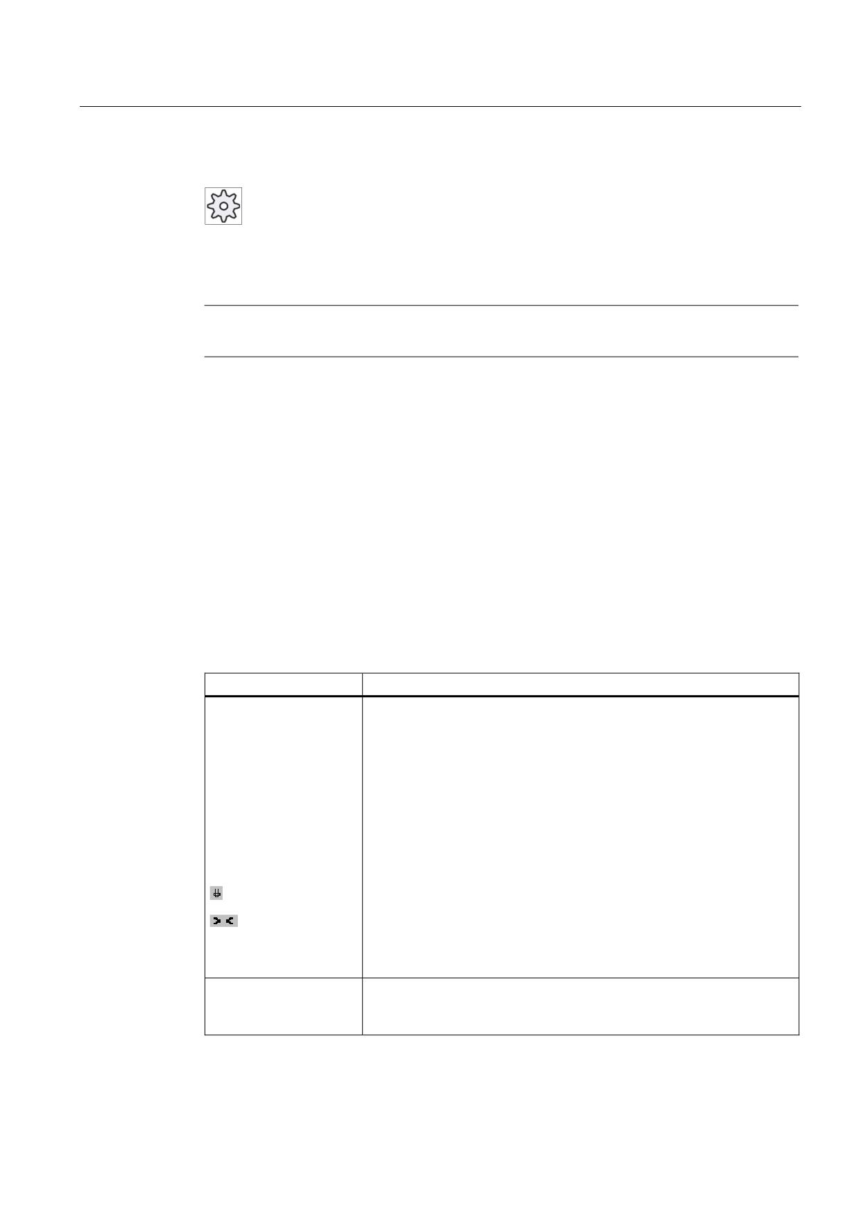
Tool management
8.5 Tool list
Machine manufacturer
The tool length of the workpiece probe is measured to the center of the ball
(length m) or to the ball circumference (length u).
Please refer to the machine manufacturer's specifications.
Note
An electronic workpiece probe must be calibrated before use.
8.5
Tool list
8.5.1
Tool list
All parameters and functions that are required to create and set up the tools are displayed in
the tool list.
Each tool is uniquely identified by the tool identifier and the replacement tool number.
Tool parameters
Column heading
Meaning
Location
Magazine/location number
• The magazine location numbers
The magazine number is specified first, followed by the location
number in the magazine.
If there is only one magazine, only the location number is displayed.
BS
• Load position in the load magazine
The following icons can also be displayed for other magazine types (e.g.
for a chain):
• Spindle location as an icon
* If activated in magazine
• Locations for gripper 1 and gripper 2 (applies only when a spindle with
selection
dual gripper is used) as icons.
Type
Tool type
Specific tool offset data is displayed depending on the tool type
(represented as an icon).
Universal
Operating Manual, 03/2013, 6FC5398-6AP40-3BA1
191
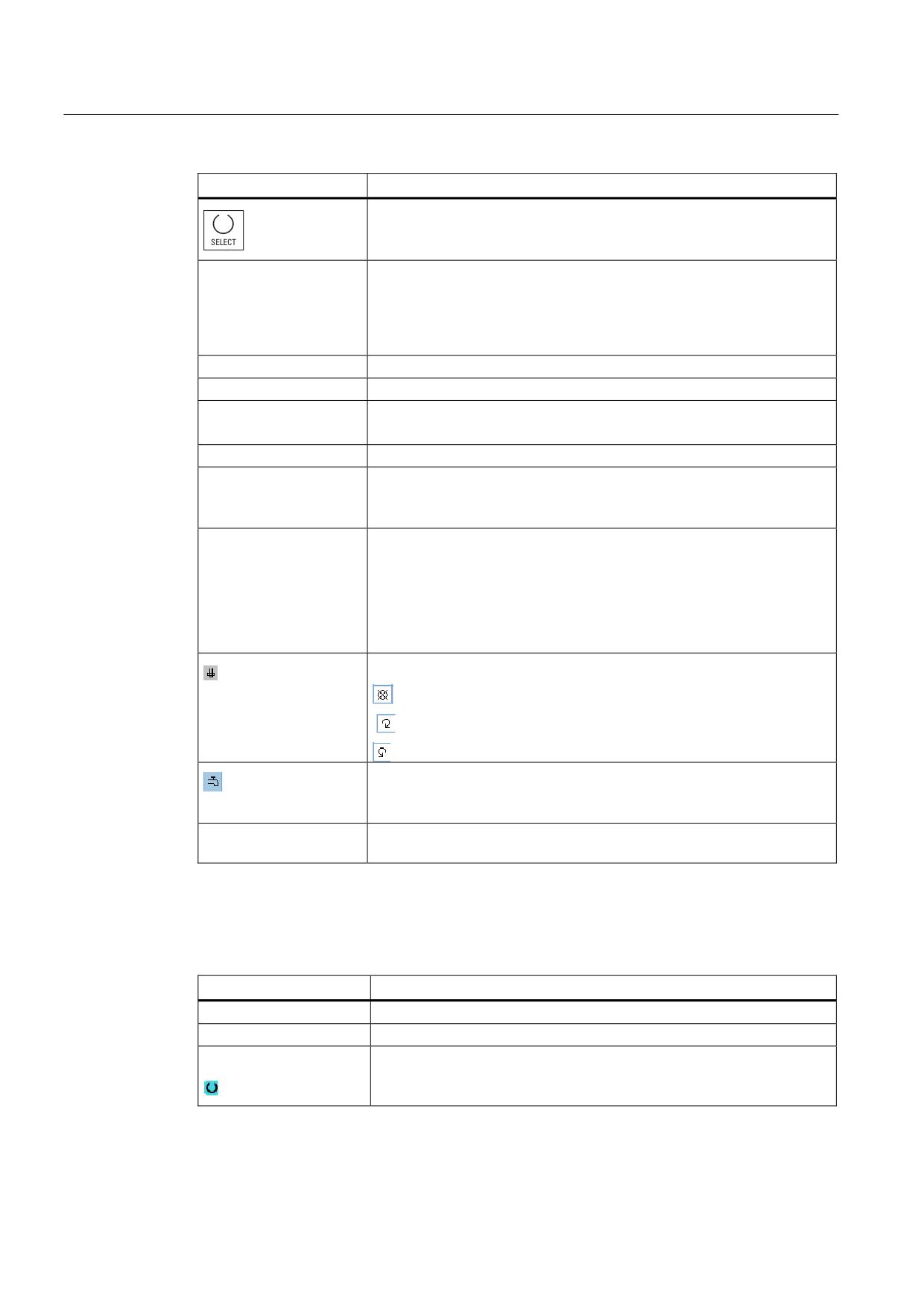
Tool management
8.5 Tool list
Column heading
Meaning
You have the option of changing the tool type using the <SELECT> key.
Tool name
The tool is identified by the name and the replacement tool number. You
may enter the names as text or numbers.
Note: The maximum length of tool names is 31 ASCII characters. The
number of characters is reduced for Asian characters or Unicode
characters. The following special characters are not permitted: | # ".
ST
Replacement tool number (for replacement tool strategy)
D
Cutting edge number
Length
Tool length
Geometry data, length
Radius
Tool radius
Tip angle or
Tip angle for Type 200 - twist drill and Type 220 - centering tool and Type
230 countersink
Pitch
Pitch for Type 240 - tap
N
Number of teeth for Type 100 - milling tool, Type 110 - ball end mill for
cylindrical die-sinking cutter, Type 111 - ball end mill or tapered die-
sinking cutter, Type 120 - end mill, Type 121 - end mill with corner
rounding, Type 130 - angle head cutter, Type 131 - angle head cutter with
corner rounding, Type 140 - facing tool, Type 150 - side mill, Type 155 -
bevel cutter, Type 156 - bevel cutter with corner rounding and Type 157 -
tapered die-sinking cutter.
Direction of spindle rotation
Spindle is not switched on
CW spindle rotation
CCW spindle rotation
Coolant 1 and 2 (e.g. internal and external cooling) can be switched on
and switched off.
The coolant infeed at the machine does not necessarily have to be set-up.
M1 - M4
Other tool-specific functions such as additional coolant infeed, monitoring
functions for speed, tool breakage, etc.
Further parameters
If you have created unique cutting edge numbers, they will be displayed in the first column.
Column heading
Meaning
D no.
Unique cutting edge number
SN
Cutting edge number
EC
Setting-up offsets
Display of the available setup offsets
Universal
192
Operating Manual, 03/2013, 6FC5398-6AP40-3BA1
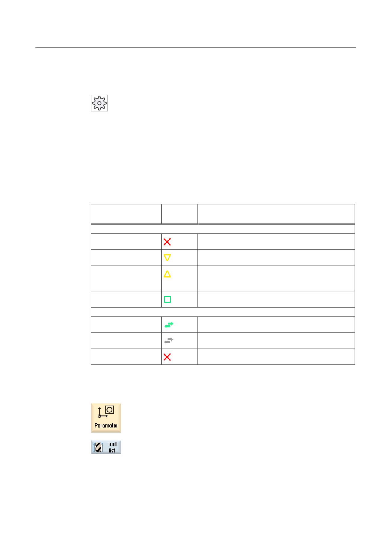
Tool management
8.5 Tool list
You use the configuration file to specify the selection of parameters in the list.
Machine manufacturer
Please refer to the machine manufacturer's specifications.
References
Information about the configuration and setup of the tool list can be found in the following
references:
SINUMERIK Operate (IM9) / SINUMERIK 840D sl Commissioning Manual
Icons in the tool list
Icon/
Meaning
Marking
Tool type
Red "X"
The tool is disabled.
Yellow triangle pointing
The prewarning limit has been reached.
downward
Yellow triangle pointing
The tool is in a special state.
upward
Place the cursor on the marked tool. A tooltip provides a
short description.
Green border
The tool is preselected.
Magazine/location number
Green double arrow
The magazine location is positioned at the change position.
Gray double arrow
The magazine location is positioned at the loading position.
(configurable)
Red "X"
The magazine location is disabled.
Procedure
1.
Select the "Parameter" operating area.
2.
Press the "Tool list" softkey.
The "Tool List" window opens.
Universal
Operating Manual, 03/2013, 6FC5398-6AP40-3BA1
193
Tool management
8.5 Tool list
8.5.2
Creating a new tool
When creating a new tool, the "New tool - favorites" window offers you a number of selected
tool types, known as "favorites".
If you do not find the desired tool type in the favorites list, then select the milling, drilling,
grinding or special tool via the corresponding softkeys.
Note
Grinding tools
Only grinding tools are available depending on the particular machine configuration.
Procedure
1..
The tool list is opened.
2.
Place the cursor in the tool list at the position where the new tool
should be stored.
For this, you can select an empty magazine location or the NC tool
memory outside of the magazine.
You may also position the cursor on an existing tool in the area of the
NC tool memory. Data from the displayed tool will not be overwritten.
3.
Press the "New tool" softkey.
The "New tool - favorites" window opens.
- OR -
If you want to create a tool that is not in the "Favorites" list, press the
softkey "Cutters 100-199", "Drill 200-299", Grinders 400-499" or "
Spec.tool 700-900".
The "New tool - milling cutter", "New tool - drill", "New tool - grinding
tool" or "New tool - special tools" window opens.
4.
Select the tool by placing the cursor on the corresponding icon.
5.
Press the "OK" softkey.
The tool is added to the tool list with a predefined name. If the cursor
is located on an empty magazine location in the tool list, then the tool
is loaded to this magazine location.
The tool creation sequence can be defined differently.
Universal
194
Operating Manual, 03/2013, 6FC5398-6AP40-3BA1
Tool management
8.5 Tool list
Multiple load points
If you have configured several loading points for a magazine, then the "Select loading point"
window appears when a tool is created directly in an empty magazine location or when the
"Load" softkey is pressed.
Select the required load point and confirm with the "OK" softkey.
Additional data
If configured accordingly, the "New tool" window opens after the required tool has been
selected and confirmed with "OK".
You can define the following data in this window:
● Names
● Tool location type
● Size of tool
References:
For a description of configuration options, refer to the
Commissioning Manual SINUMERIK Operate / SINUMERIK 840D sl
8.5.3
Additional data
The following tool types require geometry data that is not included in the tool list display.
Tools with additional geometry data
Tool type
Additional parameters
111 Conical ballhead cutter
Corner radius
121 End mill with corner
Corner radius
rounding
130 Angle head cutter
Geometry length (length X, length Y, length Z)
Wear length (Δ length X, Δ length Y, Δ length Z)
Adapter length (length X, length Y, length Z)
V (direction vector 1 - 6)
Vector X, vector Y, vector Z
131 Angle head cutter with
Geometry length (length X, length Y, length Z)
corner rounding
Corner radius
Wear length (Δ length X, Δ length Y, Δ length Z)
Adapter length (length X, length Y, length Z)
V (direction vector 1 - 6)
Vector X, vector Y, vector Z
Universal
Operating Manual, 03/2013, 6FC5398-6AP40-3BA1
195
Tool management
8.5 Tool list
Tool type
Additional parameters
140 Face milling
External radius
Tool angle
155 Bevel cutter
Taper angle
156 Bevel cutter with corner
Corner radius
rounding
Taper angle
157 Conical die-milling cutter
Taper angle
585 Calibration tool
Geometry length (length X, length Y, length Z)
Wear length (Δ length X, Δ length Y, Δ length Z)
710 3D-probe milling
Geometry length (length X, length Y, length Z)
Wear length (Δ length X, Δ length Y, Δ length Z)
712 Mono-probe
Geometry length (length X, length Y, length Z)
Wear length (Δ length X, Δ length Y, Δ length Z)
713 L-probe
Geometry length (length X, length Y, length Z)
Wear length (Δ length X, Δ length Y, Δ length Z)
Boom length (length)
714 Star-type probe
Geometry length (length X, length Y, length Z)
Wear length (Δ length X, Δ length Y, Δ length Z)
Outer diameter (∅)
You can use the configuration file to specify the data to be displayed for specific tool types in
the "Additional Data" window.
Machine manufacturer
Please refer to the machine manufacturer's specifications.
Procedure
1.
The tool list is opened.
2.
In the list, select an appropriate tool, e.g. an angle head cutter.
3.
Press the "Additional data" softkey.
The "Additional Data - ..." window opens.
The "Additional data" softkey is only active if a tool for which the
"Additional Data" window is configured is selected.
Universal
196
Operating Manual, 03/2013, 6FC5398-6AP40-3BA1
Tool management
8.5 Tool list
8.5.4
Managing several cutting edges
In the case of tools with more than one cutting edge, a separate set of offset data is
assigned to each cutting edge. The number of possible cutting edges depends on the
controller configuration.
Tool cutting edges that are not required can be deleted.
Procedure
1.
The tool list is opened.
2.
Position the cursor on the tool for which you would like to store more
cutting edges.
3.
Press the "Edges" softkey in the "Tool list".
4.
Press the "New cutting edge" softkey.
A new data set is stored in the list.
The cutting edge number is incremented by one and the offset data is
assigned the values of the cutting edge on which the cursor is
positioned.
5.
Enter the offset data for the 2nd cutting edge.
6.
Repeat this process if you wish to create more tool edge offset data.
7.
Position the cursor on the cutting edge that you want to delete and
press the "Delete cutting edge" softkey.
The data set is deleted from the list. The first tool cutting edge cannot
be deleted.
Universal
Operating Manual, 03/2013, 6FC5398-6AP40-3BA1
197
Tool management
8.5 Tool list
8.5.5
Deleting a tool
Tools that are no longer in use can be deleted from the tool list for a clearer overview.
Procedure
1.
The tool list is opened.
2.
Place the cursor on the tool that you would like to delete.
3.
Press the "Delete tool" softkey.
A safety prompt is displayed.
4.
Press the "OK" softkey if you really want to delete the tool.
Use this softkey to delete the tool.
If the tool is in a magazine location, it is unloaded and then deleted.
Multiple load points - tool in magazine location
If you have configured several loading points for a magazine, then the "Loading Point
Selection" window appears after pressing the "Delete tool" softkey.
Select the required load point and press the "OK" softkey to unload and delete the tool.
8.5.6
Loading and unloading tools
You can load and unload tools to and from a magazine via the tool list. When a tool is
loaded, it is taken to a magazine location. When it is unloaded, it is removed from the
magazine and stored in the NC memory.
When you are loading a tool, the application automatically suggests an empty location. You
may also directly specify an empty magazine location.
You can unload tools from the magazine that you are not using at present. HMI then
automatically saves the tool data in the NC memory.
Should you want to use the tool again later, simply load the tool with the tool data into the
corresponding magazine location again. Then the same tool data does not have to be
entered more than once.
Universal
198
Operating Manual, 03/2013, 6FC5398-6AP40-3BA1
Tool management
8.5 Tool list
Procedure
1.
The tool list is opened.
2.
Place the cursor on the tool that you want to load into the magazine (if
the tools are sorted according to magazine location number you will find
it at the end of the tool list).
3.
Press the "Load" softkey.
The "Load to… " window opens.
The "... location" field is initialized with the number of the first empty
magazine location.
4.
Press the "OK" softkey to load the tool into the suggested location.
- OR -
Enter the location number you require and press the "OK" softkey.
- OR -
Press the "Spindle" softkey.
The tool is loaded into the specified magazine location or spindle.
Loading empty magazine location directly with tool
1.
Position the cursor at an empty magazine location where you want to
load a tool and press the "Load" softkey.
The "Load with ..." window opens.
Select the desired tool in the " ... Tool" field and press the "OK" softkey.
Several magazines
If you have configured several magazines, the "Load to ..." window appears after pressing
the "Load" softkey.
If you do not want to use the suggested empty location, then enter your desired magazine
and magazine location. Confirm your selection with "OK".
Multiple load points
If you have configured several loading points for a magazine, then the "Loading Point
Selection" window appears after pressing the "Load" softkey.
Select the required loading point and confirm with "OK".
Universal
Operating Manual, 03/2013, 6FC5398-6AP40-3BA1
199