SINUMERIK 840D sl/828D Universal. Operating Manual (2013) - page 4
Ctrl-Energy
12.6 Using the energy-saving profile
References
Information on the configuration of the energy-saving profiles is provided in the following
reference:
System Manual "Ctrl-Energy", SINUMERIK 840D sl / 828D
Procedure
1.
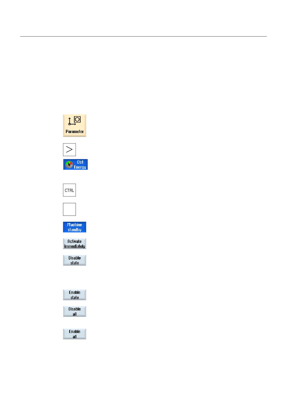
Select the "Parameter" operating area.
2.
Press the menu forward key and then the "Ctrl-Energy" softkey.
- OR -
Press the <CTRL> + <E> keys.
+
(
The "SINUMERIK Ctrl-Energy Energy-Saving Profiles" window opens.
3.
Position the cursor on the required energy-saving profile and press the
"Activate immediately" softkey if you wish to directly activate this state.
4.
Position the cursor on the required energy-saving profile and press the
"Disable profile" softkey if you wish to disable this state.
The profile is disabled. The energy-saving profile cannot be active, i.e. it
is grayed out and displayed without time details.
The labeling of the "Disable profile" softkey changes to "Enable profile".
Press the "Enable profile" softkey in order to withdraw the energy-
saving profile disable.
5.
Press the "Disable all" softkey in order to disable all states.
All the profiles are disabled and can be non-active.
The labeling of the "Disable all" softkey changes to "Enable all".
6.
Press the "Enable all" softkey to withdraw the disable for all profiles.
Universal
300
Operating Manual, 03/2013, 6FC5398-6AP40-3BA1
Easy Message (828D only)
13
13.1
Overview
Easy Message enables you to be informed about certain machine states by means of SMS
messages via a connected modem:
● For example, you would like to be informed about emergency stop states
● You would like to know when a batch has been completed
Control commands
● HMI commands are used to activate or deactivate a user.
Syntax: [User ID] deactivate¸ [User ID] activate
● A special area is reserved in the PLC to which you can send commands in the form of
PLC bytes using SMS commands.
Syntax: [User ID] PLC DataByte
The user ID is optional and required only if a corresponding ID has been specified in the
user profile. The string PLC indicates that a PLC byte is to be written. It is followed by the
data byte to be written in the following format: Base#Value. Base can take the values 2,
10 and 16 and defines the number base. Then follows the separator # and the value of
the byte. Only positive values are allowed to be sent.
Examples:
2#11101101
10#34
16#AF
Machine manufacturer
Please refer to the machine manufacturer's specifications.
Active users
In order to receive an SMS message for certain events, you must be activated as user.
User logon
As registered user, you can log on via SMS to inquire about messages.
Action log
You can obtain precise information about incoming and outgoing messages via SMS logs.
Universal
Operating Manual, 03/2013, 6FC5398-6AP40-3BA1
301
Easy Message (828D only)
13.1 Overview
References
Information on the GSM modem can be found in the
PPU SINUMERIK 828D Manual
Calling the SMS Messenger
1.
Select the "Diagnostics" operating area.
2.
Press the "Easy Msg." softkey.
Universal
302
Operating Manual, 03/2013, 6FC5398-6AP40-3BA1
Easy Message (828D only)
13.2 Activating Easy Message
13.2
Activating Easy Message
To commission the connection to the modem for the SMS Messenger, activate the SIM card
at the initial start-up.
Requirement
The modem is connected and activated.
Machine manufacturer
The modem is activated via the machine data 51233
$MSN_ENABLE_GSM_MODEM.
Please refer to the machine manufacturer's specifications.
Procedure
Activating the SIM card
1.
Press the "Easy Msg." softkey.
The "SMS Messenger" window appears.
"Status" shows that the SIM card has not been activated with a PIN.
2.
Enter the PIN, repeat the PIN and press the "OK" softkey.
3.
If you made an incorrect entry several times, enter the PUK code in the
"PUK Input" window and press the "OK" softkey to activate the PUK
code.
The "PIN input" window is opened and you can enter the PIN number as
usual.
Activating a new SIM card
1.
Press the "Easy Msg." softkey.
The "SMS Messenger" window appears.
"Status" shows that the connection to the modem has been activated.
2.
Press the "Settings" softkey.
3.
Press the "Delete PIN" softkey to delete the stored PIN.
Enter the new PIN in the "PIN Input" window at the next power up.
Universal
Operating Manual, 03/2013, 6FC5398-6AP40-3BA1
303
Easy Message (828D only)
13.3 Creating/editing a user profile
13.3
Creating/editing a user profile
User identification
Display
Meaning
User name
Name of the user to be created or logged on.
Telephone number
Telephone number of the user to which the messages are to be sent.
The telephone number must include the country code in order that
control commands can identify the sender (e.g. +491729999999)
User ID
The user ID has 5 digits (e.g. 12345)
• It is used to activate and deactivate the user via SMS. (e.g.
"12345 activate")
• The ID is used to additionally verify the incoming and outgoing
messages and to activate the control commands.
Events that can be selected
You must set-up the events for which you receive notification.
Requirement
The modem is connected.
Procedure
Creating a new user
1.
Press the "User profiles” softkey.
The "User Profiles" window appears.
2.
Press the "New" softkey.
3.
Enter the name and telephone number of the user.
4.
If required, enter the ID number of the user.
5.
In the area "send SMS for the following events" area, activate the
appropriate checkbox and when required, enter the desired value (e.g.
the unit quantity, which when it is reached, a notification should be
sent).
- OR -
Press the "Default" softkey.
The appropriate window is opened and displays the default values.
Universal
304
Operating Manual, 03/2013, 6FC5398-6AP40-3BA1
Easy Message (828D only)
13.4 Setting-up events
6.
Press the "Send test message" softkey.
An SMS message with predefined text is sent to the specified telephone
number.
Editing user data and events
1.
Select the user whose data you want to edit and press the "Edit"
softkey.
The input fields can be edited.
2.
Enter new data and activate the desired settings.
- OR -
Press the "Default" softkey to accept the default values.
13.4
Setting-up events
In the "Send SMS for the following events" area, select the events using the check box,
which when they occur, an SMS is sent to the user.
● Programmed messages from the part program (MSG)
In the part program, program an MSG command via which you receive an SMS.
Example: MSG ("SMS: An SMS from a part program")
● Select the following events using the <SELECT> key
- The workpiece counter reaches the following value
An SMS is sent if the workpiece counter reaches the set value.
- The following program progress is reached (percent)
An SMS is sent if, when executing a part program, the set progress is reached.
- Actual NC program reaches runtime (minutes)
An SMS is sent after the set runtime has been reached when executing an NC
program.
- Tool usage time reaches the following value (minutes)
An SMS is sent if the usage time of the tool reaches the set time when executing a
part program (derived from $AC_CUTTING_TIME).
● Messages/alarms from the Tool Manager
An SMS is sent if messages or alarms are output to the Tool Manager.
● Measuring cycle messages for tools
An SMS is sent if measuring cycle messages are output that involve tools.
● Measuring cycle messages for workpieces
An SMS is sent if measuring cycle messages are output that involve workpieces.
Universal
Operating Manual, 03/2013, 6FC5398-6AP40-3BA1
305
Easy Message (828D only)
13.4 Setting-up events
●
Sinumerik messages/alarms (error when executing)
An SMS is sent if NCK alarms or messages are output that cause the machine to come to
a standstill.
●
Machine faults
An SMS is sent if PLC alarms or messages are output that cause the machine to come to
a standstill (i.e. PLC alarms with Emergency Off response).
●
Maintenance intervals
An SMS is sent if the service planner registers pending maintenance work.
●
Additional alarm numbers:
Here, specify additional alarms where you should be notified if they occur.
You can enter individual alarms, several alarms or alarm number ranges.
Examples:
1234,400
1000-2000
100,200-300
Requirement
●
The user profile window is opened.
●
You selected the event "Measuring cycle messages for tools", "Measuring cycle
messages for workpieces", "Sinumerik messages/alarms (errors when executing)",
"Machine faults" or "Maintenance intervals".
Editing events
1.
Activate the required check box and press the "Details" softkey.
The appropriate window opens (e.g. "Measuring cycle messages for
workpieces") and shows a list of the defined alarm numbers.
2.
Select the corresponding entry and press the "Delete" softkey to
remove the alarm number from the list.
- OR -
Then press the "New" softkey if you wish to create a new entry.
The "Create new entry" window opens.
Enter the data and press the "OK" softkey to add the entry to the list.
Press the "Save" softkey to save the settings for the result.
3.
Press the "Standard" softkey to return to the standard settings for the
events.
Universal
306
Operating Manual, 03/2013, 6FC5398-6AP40-3BA1
Easy Message (828D only)
13.5 Logging an active user on and off
13.5
Logging an active user on and off
Only active users receive an SMS message for the specified events.
You can activate users, already created for Easy Message, with certain control commands
via the user interface or via SMS.
The connection has been established to the modem.
Procedure
1.
Press the "User profiles” softkey.
2.
Select the desired user in the User name field and press the "User
active” softkey
Note
Repeat step 2 to activate further users.
- OR -
Send an SMS with the User ID and the "activate" text to the control (e.g.
"12345 activate")
If the telephone number and the user ID match the stored data, the user
profile is activated.
You receive a message of success or failure per SMS.
3.
Press the "User active” softkey to log off an activated user.
- OR -
Send an SMS with the "deactivate" text (e.g. "12345 deactivate") to log
off from the Messenger.
An SMS message is not sent to the deactivated user for the events
specified in the user profile.
Universal
Operating Manual, 03/2013, 6FC5398-6AP40-3BA1
307
Easy Message (828D only)
13.6 Displaying SMS logs
13.6
Displaying SMS logs
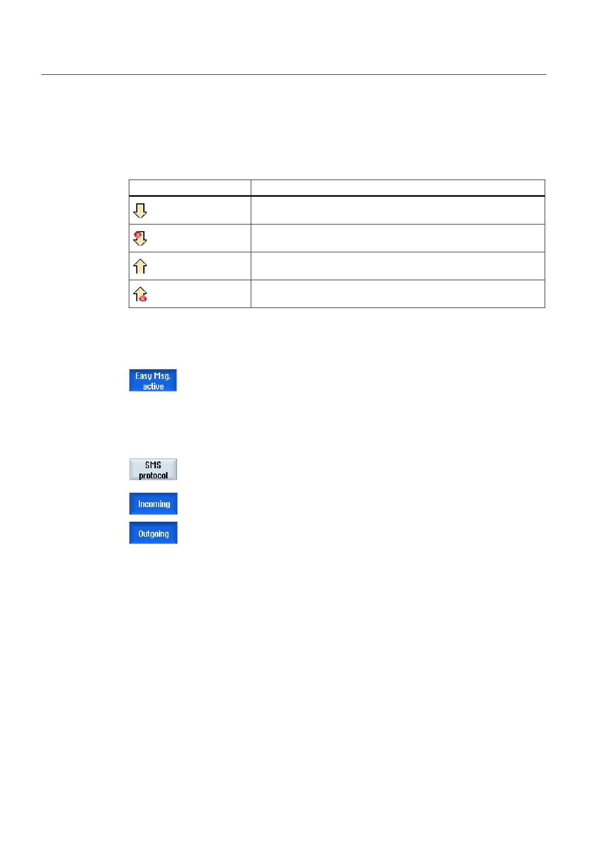
The SMS data traffic is recorded in the "SMS Log" window. In this way, it is possible to see
the chronological sequence of activates when a fault occurs.
Symbols
Description
Incoming SMS message for the Messenger.
Message that has reached the Messenger, but which has not been
processed (e.g. incorrect user ID or unknown account).
SMS message sent to a user.
Message that has not reached the user because of an error.
Requirement
The connection has been established to the modem.
Procedure
1.
Press the "SMS log" softkey.
The "SMS Log" window appears.
All the messages that have been sent or received by the Messenger are
listed.
Note
Press the "Incoming" or "Outgoing" softkey to restrict the list.
Universal
308
Operating Manual, 03/2013, 6FC5398-6AP40-3BA1
Easy Message (828D only)
13.7 Making settings for Easy Message
13.7
Making settings for Easy Message
You can change the following Messenger configuration in the "Settings" window:
● Name of the controller that is part of an SMS message
● Number of sent messages
- The SMS counter provides information on all sent messages.
- Limit the number of sent messages in order to receive an overview of the costs
through SMS messages, for example.
Setting the SMS counter to zero
When a set limit is reached, no further SMS messages are sent.
Press the "Reset SMS counter" softkey to reset the counter to zero.
Requirement
The connection has been established to the modem.
Procedure
1.
Press the "Settings" softkey.
2.
Enter an arbitrary name for the controller in the "Machine name" field.
3.
If you want to limit the number of sent SMS messages then select the
"Specify limit for SMS counter" entry and enter the desired number.
When the maximum number of messages is reached, you obtain a
corresponding error message.
Note
Check the SMS log to see the exact time when the limit was reached.
- OR -
3.
Press the "Default" softkey.
If you have freely selected a machine name, this is replaced by a
default name (e.g. 828D).
Universal
Operating Manual, 03/2013, 6FC5398-6AP40-3BA1
309
Easy Message (828D only)
13.7 Making settings for Easy Message
Universal
310
Operating Manual, 03/2013, 6FC5398-6AP40-3BA1
Easy Extend (828D only)
14
14.1
Overview
Easy Extend enables machines to be retrofitted with additional units, which are controlled by
the PLC or that require additional NC axes (such as bar loaders, swiveling tables or milling
heads), at a later point in time. These additional devices are easily commissioned, activated,
deactivated or tested with Easy Extend.
The communication between the operator component and the PLC is performed via a PLC
user program. The sequences to be executed for the installation, activation, deactivation and
testing of a device are stored in a statement script.
Available devices and device states are displayed in a list. The view of the available devices
can be controlled for users according to their access rights.
The subsequent chapters are selected for example only and are not available in every
statement list.
Machine manufacturer
Please refer to the machine manufacturer's specifications.
Up to 64 devices can be managed.
References
SINUMERIK 828D Turning and Milling Commissioning Manual
Universal
Operating Manual, 03/2013, 6FC5398-6AP40-3BA1
311
Easy Extend (828D only)
14.2 Enabling a device
14.2
Enabling a device
The available device options are protected by a password.
Machine manufacturer
Please refer to the machine manufacturer's specifications.
Procedure
1.
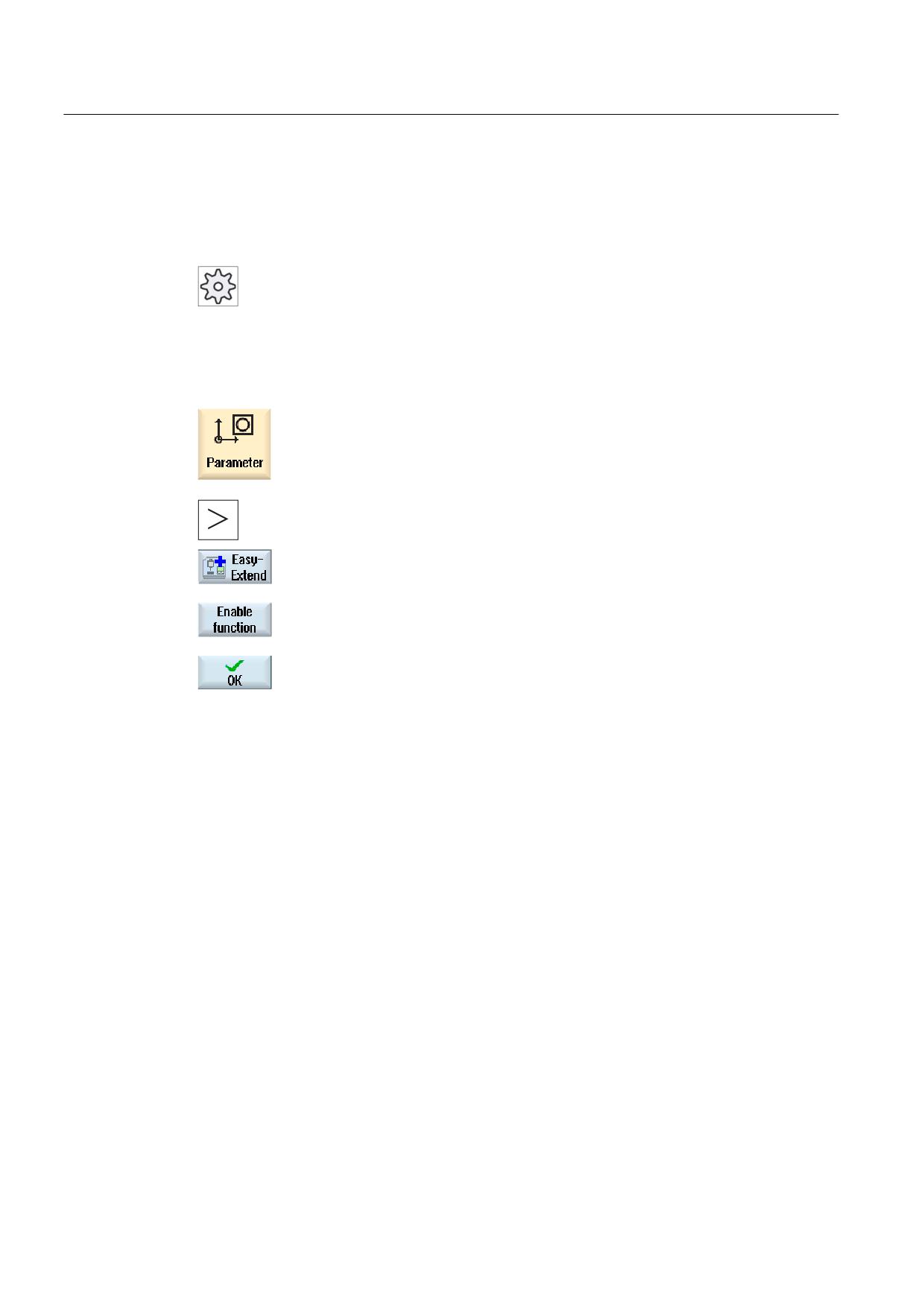
Select the "Parameter" operating area.
2.
Press the menu forward key and then the "Easy Extend" softkey.
A list of the connected devices is displayed.
3.
Press the "Enable function" softkey.
The "Enabling of the Devices Option" window is opened.
4.
Enter the option code and press the "OK" softkey.
A tick appears in the appropriate checkbox in the "Function" column
and the function is enabled.
Universal
312
Operating Manual, 03/2013, 6FC5398-6AP40-3BA1
Easy Extend (828D only)
14.3 Activating and deactivating a device
14.3
Activating and deactivating a device
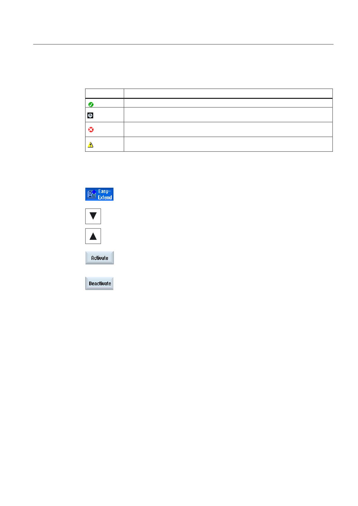
Status
Meaning
Device activated
System waiting for PLC checkback signal
Device faulty
Interface error in the communication module
Procedure
1.
Easy Extend is opened.
2
You can select the desired device in the list with the <Cursor up> and
<Cursor down> keys.
3.
Position the cursor on the device option for which the function has been
unlocked and press the "Activate" softkey.
The device is marked as activated and can now be used.
4.
Select the desired activated device and press the "Deactivate" softkey
to switch the device off again.
Universal
Operating Manual, 03/2013, 6FC5398-6AP40-3BA1
313
Easy Extend (828D only)
14.4 Commissioning Easy Extend
14.4
Commissioning Easy Extend
As a rule, the "Easy Extend" function has already been commissioned by the machine
manufacturer. If a first commissioning has not been performed or if, for example, function
tests are to be performed again (e.g. when retrofitting additional devices), this is possible at
any time.
The "Start-up" softkey has been declared as Manufacturer data class (M).
Procedure
1.
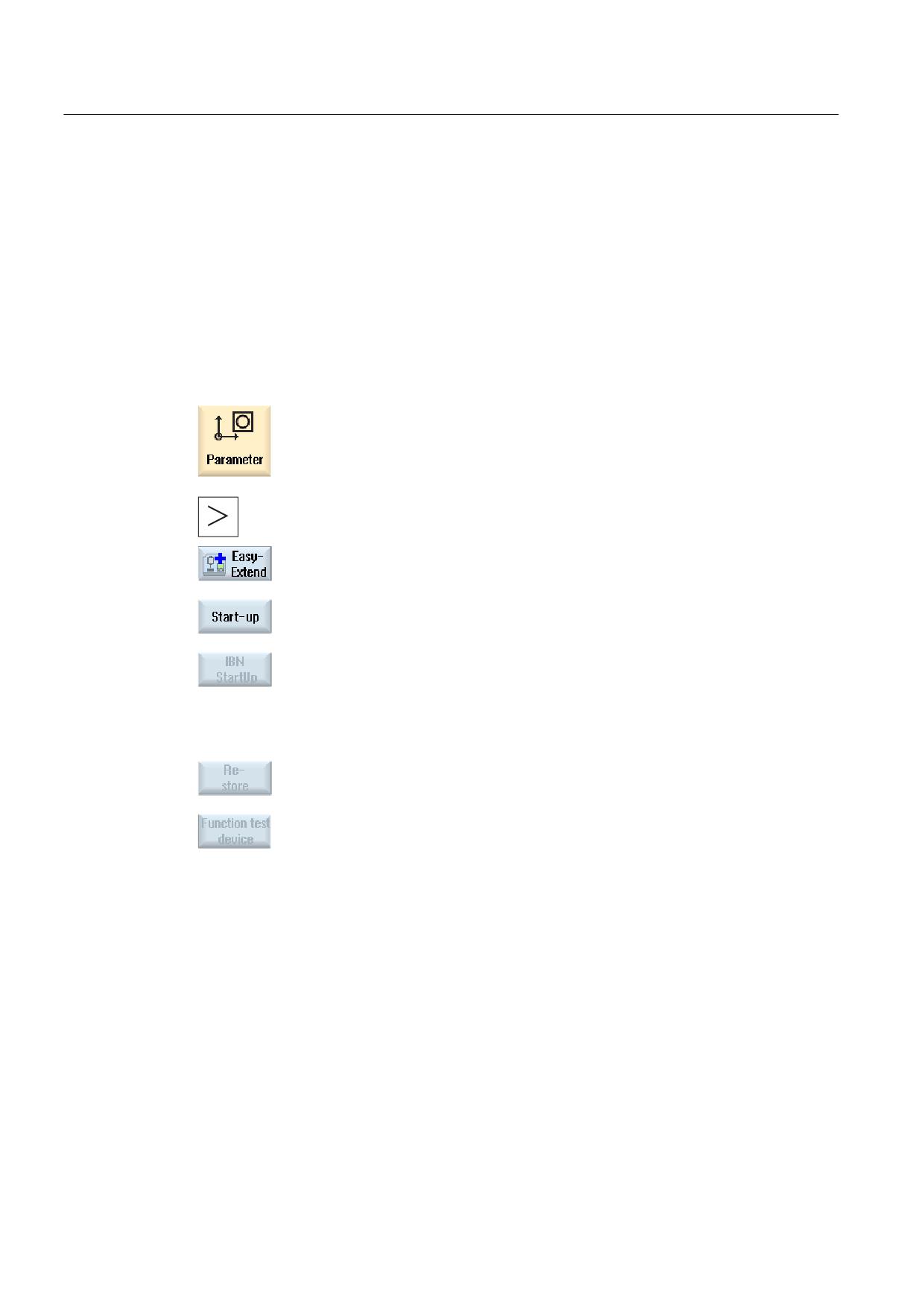
Select the "Parameter" operating area.
2.
Press the menu forward key and then the "Easy Extend" softkey.
3.
Press the "Start-up" softkey.
A new vertical softkey bar appears.
4.
Press the "Comm. start-up" softkey to start the commissioning.
Before starting, a complete data backup is generated which you can
then use in an emergency.
5.
Press the "Cancel" softkey if you want to abort the commissioning
prematurely.
6.
Press the "Restore" softkey to load the original data.
7.
Press the "Device function test" softkey to test the machine
manufacturer's intended function.
Universal
314
Operating Manual, 03/2013, 6FC5398-6AP40-3BA1
Service Planner (828D only)
15
15.1
Performing and monitoring maintenance tasks
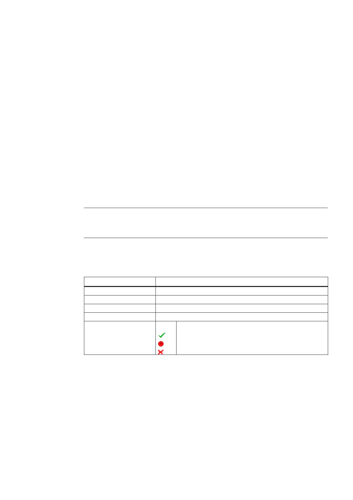
With the "Service Planner", maintenance tasks have been set up that have to be performed
at certain intervals (e.g. top up oil, change coolant).
A list is displayed of all the maintenance tasks that have been set up together with the time
remaining until the end of the specified maintenance interval.
The current status can be seen in the status display.
Messages and alarms indicate when a task has to be performed.
Acknowledging a maintenance task
Acknowledge the message when a maintenance task has been completed.
Note
Protection level
You require protection level 2 (service) to acknowledge completed maintenance tasks.
Service Planner
Display
Meaning
Pos
Position of the maintenance task in the PLC interface.
Maintenance task
Name of the maintenance task.
Interval [h]
Maximum time until next servicing in hours.
Remaining time [h]
Time until the interval expires in hours.
Status
Display of the current status of a maintenance task.
The maintenance task has been started.
The maintenance task is completed.
The maintenance task is deactivated.
Universal
Operating Manual, 03/2013, 6FC5398-6AP40-3BA1
315
Service Planner (828D only)
15.1 Performing and monitoring maintenance tasks
Procedure
1.
Select the "Diagnostics" operating area.
2.
Press the menu forward key and then the "Service planner" softkey.
The window with the list of all the maintenance tasks that have been set
up appears.
3.
Perform the maintenance task when the maintenance interval has
nearly expired or when prompted to do so by alarms or a warning.
4.
After you have performed a pending maintenance task and the task is
signaled as "Completed", position the cursor at the appropriate task and
press the "Servicing performed" softkey.
A message is displayed confirming the acknowledgment, and the
maintenance interval is restarted.
Note
You can perform the maintenance tasks before the interval expires. The maintenance
interval is restarted.
Universal
316
Operating Manual, 03/2013, 6FC5398-6AP40-3BA1
Service Planner (828D only)
15.2 Set maintenance tasks
15.2
Set maintenance tasks
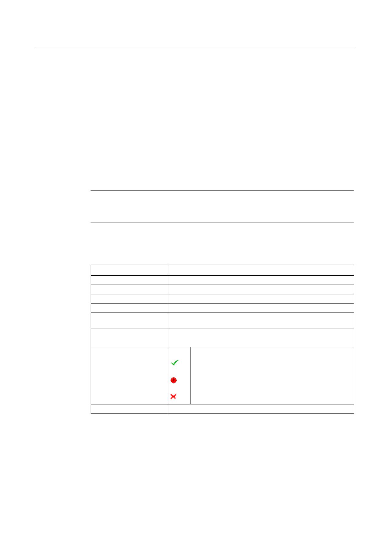
You can make the following changes in the list of maintenance tasks in the configuration
mode:
● Set up a maximum of 32 maintenance tasks with interval, initial warning and number of
warnings to be acknowledged
● Change the interval, time of the initial warning and the number of warnings to be output
● Delete a maintenance task
● Reset the times of the maintenance tasks
Acknowledging a maintenance task
You can acknowledge the maintenance tasks with the "Servicing performed" softkey.
Note
Protection level
You require protection level 1 (manufacturer) to set up and edit maintenance tasks.
Service Planner
Display
Meaning
Pos
Position of the maintenance task in the PLC interface.
Maintenance task
Name of the maintenance task.
Interval [h]
Maximum time until next servicing in hours.
1. warning [h]
Time in hours at which an initial warning is displayed.
Number of warnings
Number of warnings that can be acknowledged by the operator before
an alarm message is output for the last time.
Remaining time [h]
Time until the interval expires in hours.
The remaining time cannot be edited.
Status
Display of the current status of a maintenance task.
The maintenance task has been started.
The maintenance task is completed.
The maintenance task is deactivated, i.e. the time has been
stopped.
The status cannot be edited.
Universal
Operating Manual, 03/2013, 6FC5398-6AP40-3BA1
317
Service Planner (828D only)
15.2 Set maintenance tasks
Procedure
1.
Select the "Diagnostics" operating area.
2.
Press the menu forward key and then the "Service planner" softkey.
The window opens and displays a list of all the tasks that have been set
up.
The values cannot be edited.
3.
Press the "New maintenance task" softkey to set up a new maintenance
task.
A message informs you that a new maintenance task will be set up at
the next free position. Enter the required data in the columns and press
the "OK" softkey.
- OR -
Position the cursor on the desired maintenance task and press the
"Change task" softkey to change the associated times.
All columns except Remaining time and Status can be edited.
- OR -
Press the "Reset all" softkey to reset all the times.
- OR -
Position the cursor on the desired maintenance task and press the
"Delete task" softkey to remove the maintenance task from the list.
Universal
318
Operating Manual, 03/2013, 6FC5398-6AP40-3BA1
Ladder Viewer and Ladder add-on (828D only)
16
16.1
PLC diagnostics
A PLC user program consists to a large degree of logical operations to implement safety
functions and to support process sequences. These logical operations include the linking of
various contacts and relays. These logic operations are displayed in a ladder diagram.
Ladder add-on tool
As a rule, the failure of a single contact or relay results in a failure of the whole system.
Using the Ladder add-on tool, you can perform a PLC diagnosis in order to find fault causes
or program errors.
Editing of interrupt routines
You can edit the following interrupt programs:
● INT_100 - interrupt program, (is executed before the main program)
● INT_101 - interrupt program, (is executed after the main program)
Marshalling data
Using the Ladder add-on tool, you can "re-wire" inputs (via INT_100) or outputs (via
INT_101) for service purposes.
Generating INT_100 / INT_101 block
If one or several INT_100 or INT_101 blocks are missing, they can be added via the vertical
softkey bar. If these INT blocks exist in a project, they can be deleted via the vertical softkey
bar. You also have the opportunity to change the networks of a program on the control as
well as to save and load these changes.
Note
Saving the PLC project when changing the operating area
If you have created INT_100/INT_101 blocks or inserted, removed or edited networks in an
INT block, you must save the project before you change from the PLC area into another
operating area. Transfer the project into the PLC using the "Download to CPU" softkey. If
this is not done, all of the changes will be lost and must be re-entered.
Universal
Operating Manual, 03/2013, 6FC5398-6AP40-3BA1
319
Ladder Viewer and Ladder add-on (828D only)
16.2 Structure of the user interface
16.2
Structure of the user interface
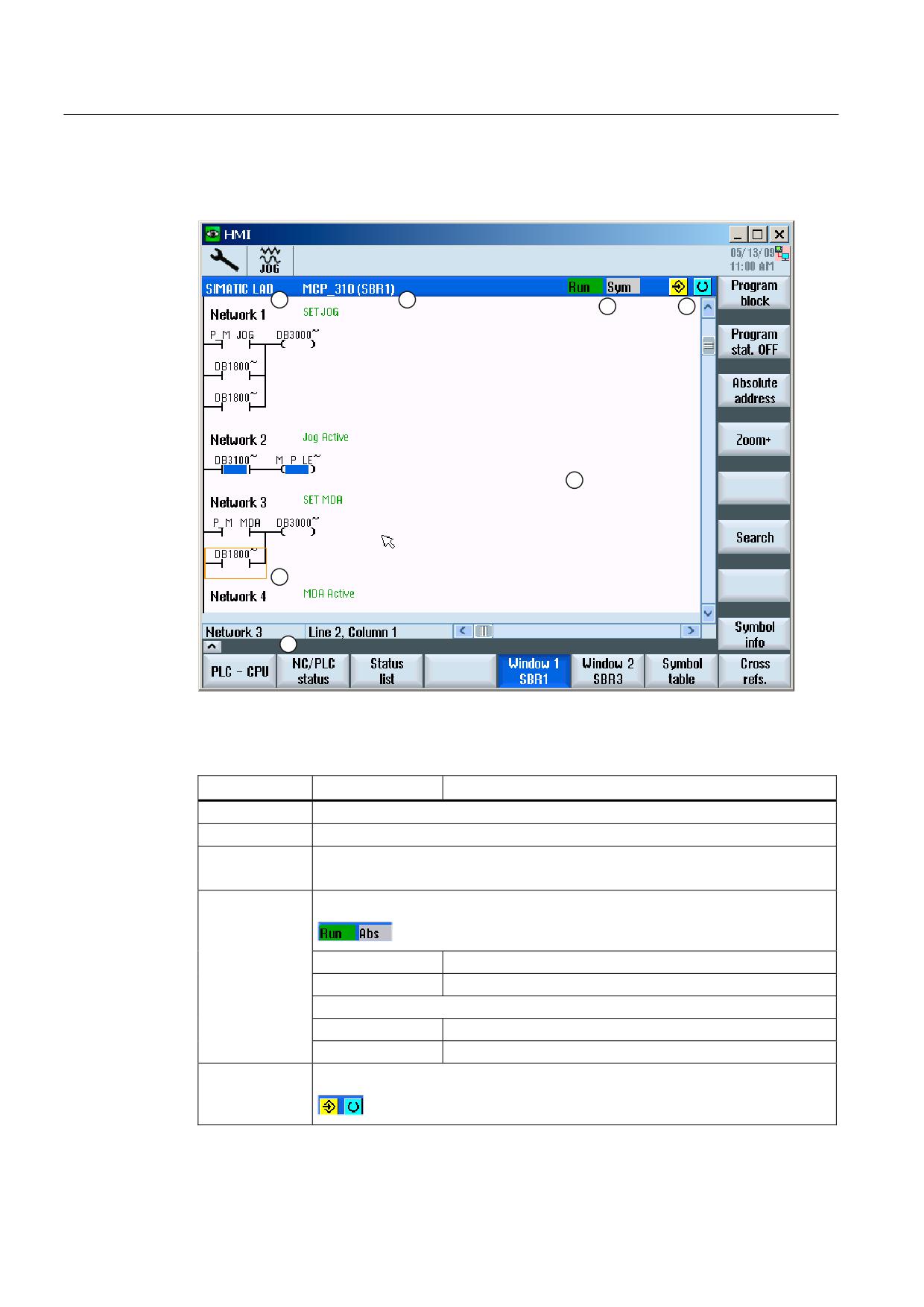
Figure 16-1 Screen structure
Table 16- 1 Key to screen layout
Screen element
Display
Meaning
1
Application area
2
Supported PLC program language
3
Name of the active program block
Representation: Symbolic name (absolute name)
4
Program status
Run
Program is running
Stop
Program is stopped
Status of the application area
Sym
Symbolic representation
Abs
Absolute representation
5
Display of the active keys (<INPUT>, <SELECT>)
Universal
320
Operating Manual, 03/2013, 6FC5398-6AP40-3BA1
Ladder Viewer and Ladder add-on (828D only)
16.3 Control options
Screen element
Display
Meaning
6
Focus
Performs the tasks of the cursor
7
Information line
Displays information, e.g. for searching
16.3
Control options
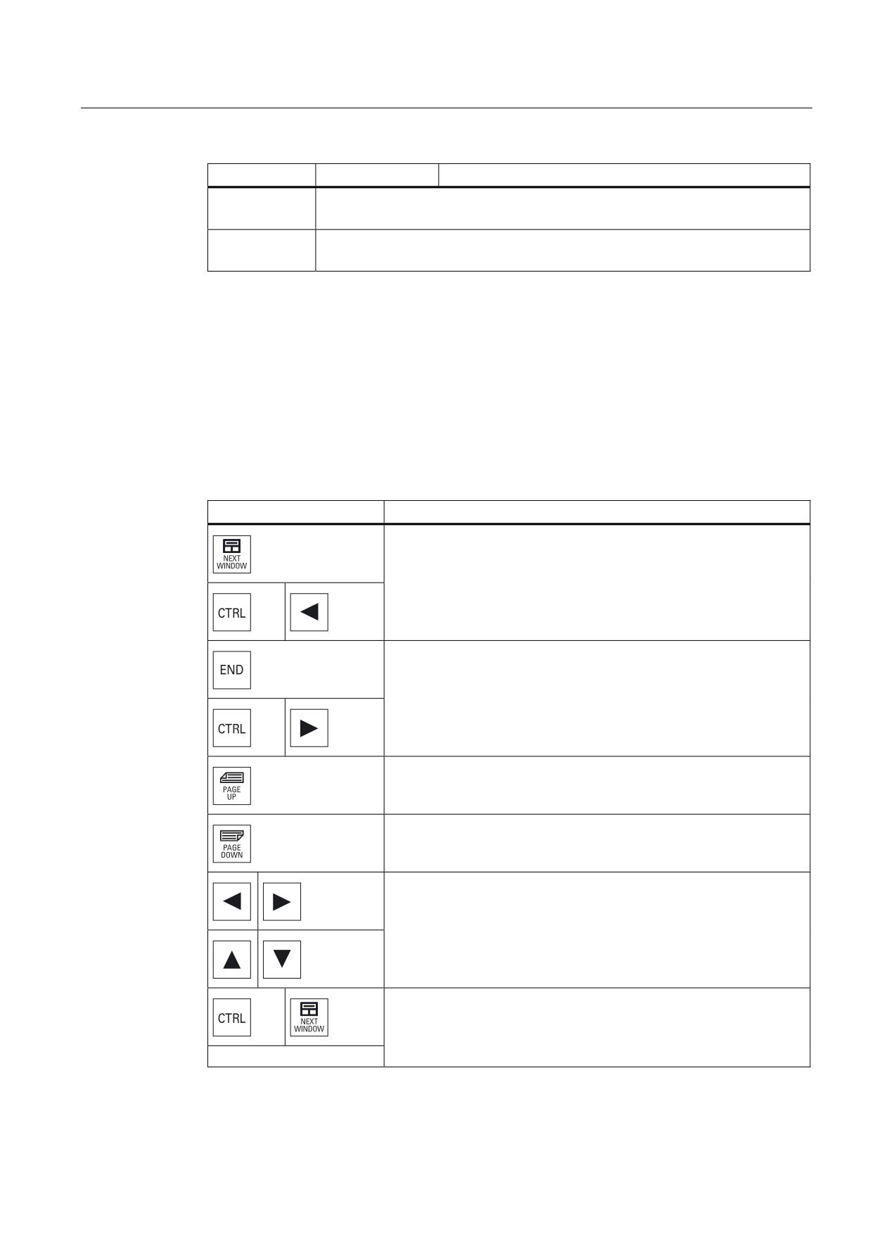
In addition to the softkeys and the navigation keys, there are further shortcuts in this area.
Shortcuts
The cursor keys move the focus over the PLC user program. When the window borders are
reached, scrolling is performed automatically.
Shortcuts
Action
To the first column of the row
To the last column of the row
Up a screen
Down a screen
One field to the left, right, up or down
To the first field of the first network
-or-
Universal
Operating Manual, 03/2013, 6FC5398-6AP40-3BA1
321
Ladder Viewer and Ladder add-on (828D only)
16.3 Control options
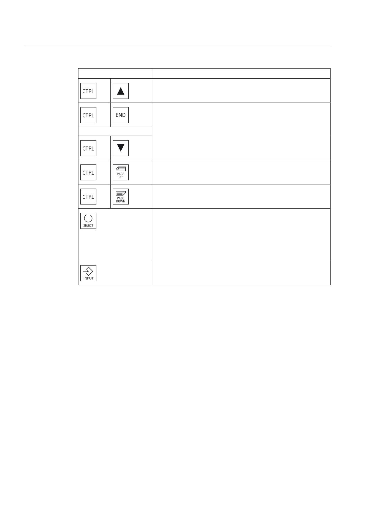
Shortcuts
Action
To the last field of the last network
-or-
Open the next program block in the same window
Open the previous program block in the same window
The function of the Select key depends on the position of the input
focus.
• Table line: Displays the complete text line
• Network title: Displays the network comment
• Command: Displays all operands
If the input focus is positioned on a command, all operands including
the comments are displayed.
Universal
322
Operating Manual, 03/2013, 6FC5398-6AP40-3BA1
Ladder Viewer and Ladder add-on (828D only)
16.4 Displaying PLC properties
16.4
Displaying PLC properties
The following PLC properties can be displayed in the "SIMATIC LAD" window:
● Operating state
● Name of the PLC project
● PLC system version
● Cycle time
● Machining time of the PLC user program
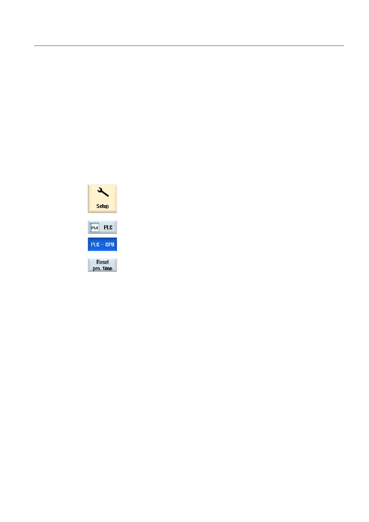
Procedure
1.
Select the "Start-up" operating area.
2.
Press the "PLC" softkey.
The ladder diagram display opens and displays the PLC information.
3.
Press the "Reset mach.time" softkey.
The data of the machining time is reset.
16.5
Displaying and editing NC/PLC variables
The "NC/PLC Variables" window enables the monitoring and modification of NC system
variables and PLC variables.
You receive the following list in which you enter the desired NC and PLC variables in order
to display the actual values.
● Variable
Address for NC/PLC variable.
Faulty variables have a red backg0round and # is displayed in the Value column.
● Comment
Arbitrary comment on the variables.
The column can be shown or hidden.
Universal
Operating Manual, 03/2013, 6FC5398-6AP40-3BA1
323
Ladder Viewer and Ladder add-on (828D only)
16.6 Displaying and editing PLC signals
● Format
Specification of the format in which the variable is to be displayed.
The format can be permanently defined (e.g. floating-point).
● Value
Display of the current value of the NC/PLC variable.
Procedure
1.
Ladder add-on tool is opened.
2.
Press the "NC/PLC variables" softkey.
The "NC/PLC Variables" window appears.
16.6
Displaying and editing PLC signals
PLC signals are displayed and can be changed here in the "PLC status list" window.
The following lists are shown
Inputs (IB)
Bit memories (MB)
Outputs (QB)
Variables (VB)
Data (DB)
Setting the address
You can go directly to the desired PLC address to monitor the signals.
Editing
You can edit the data.
Universal
324
Operating Manual, 03/2013, 6FC5398-6AP40-3BA1
Ladder Viewer and Ladder add-on (828D only)
16.7 Displaying information on the program blocks
Procedure
1.
Ladder add-on tool is opened.
2.
Press the "Status list” softkey.
The "Status List" window appears.
3.
Press the "Set address" softkey.
The "Set Address" window appears.
4.
Activate the desired address type (e.g. DB), enter the value and press
the "OK" softkey.
The cursor jumps to the specified address.
5.
Press the "Change" softkey.
The "RW" input field can be edited.
6.
Enter the desired value and press the "OK" softkey.
16.7
Displaying information on the program blocks
You can display all the logic and graphic information of a program block.
Display program block
In the "Program block" list, select the program block that you want to display.
Logic information
The following logic information is displayed in a ladder diagram (LAD):
● Networks with program parts and current paths
● Electrical current flow through a number of logical operations
Further information
● Properties
Name of the block, author, number of the subprogram, data class, date it was generated,
date of the last change and comment.
● Local variable
Name of the variable, variable type, data type and comment.
Universal
Operating Manual, 03/2013, 6FC5398-6AP40-3BA1
325
Ladder Viewer and Ladder add-on (828D only)
16.7 Displaying information on the program blocks
Access protection
If a program block is password-protected. The ladder diagram display
can be enabled using the "Protection" softkey.
Displaying the program status
1.
Press the "Program stat. OFF" softkey to hide the program status in the
status display.
2.
Press the "Program stat. ON" softkey to unhide the program status in
the status display.
Display progress status
If your PLC has the function "Progress status" available, the status values are displayed at
the time of execution of the operations. The status of the local data memory and the
accumulators is also displayed.
1.
Press the "Program stat. OFF" softkey to hide the program status in the
status display.
2.
Press the "Program stat. ON" softkey to unhide the program status in
the status display.
Change colors for displaying of progress or program status
In progress status, different colors are used to display information.
Display
Color
Signal flow of power rail, when status active
Blue
Signal flow in the networks
Blue
All operations that are active and that are executed without
Blue
error (corresponds to signal flow)
Status of the Boolean operations (corresponds to signal
Blue
flow)
Times and counters active
Green
Error during execution
Red
No signal flow
Gray
No network executed
Gray
STOP mode
Gray
Universal
326
Operating Manual, 03/2013, 6FC5398-6AP40-3BA1
Ladder Viewer and Ladder add-on (828D only)
16.7 Displaying information on the program blocks
Note
Colored display in program status
In the display of the program status only the color of the signal flow is relevant.
Enlarging/reducing the display of the ladder diagram
1.
Press the "Zoom +" softkey to enlarge the section of the ladder
diagram.
After enlarging, the "Zoom -" softkey is available.
2.
Press the "Zoom -" softkey to reduce the section of the ladder diagram
again.
Procedure
1.
Ladder add-on tool is opened.
2.
Press the "Window 1" or "Window 2" softkey.
3.
Press the "Program block" softkey.
The "Program block" list is displayed.
4.
Press the "Properties" softkey if you wish to display additional
information.
- OR -
Press the "Local variables" softkey if you wish to display data of a
variable.
Universal
Operating Manual, 03/2013, 6FC5398-6AP40-3BA1
327
Ladder Viewer and Ladder add-on (828D only)
16.8 Downloading a PLC user program
16.8
Downloading a PLC user program
Download the project data into the PLC if some changes have been made to the project data
and a new PLC user program is available.
When the project data is loaded, the data classes are saved and loaded to the PLC.
Requirement
Check whether the PLC is in Stop mode.
Note
PLC in RUN mode
If the PLC is in RUN mode, a corresponding message is displayed and the "Load in Stop"
and "Load in Run" softkeys appear.
With "Load in Stop", the PLC is set to Stop mode and the project is stored and loaded to the
CPU.
With "Load in Run", the loading operation is continued and the PLC project loaded to the
PLC. Only those data classes that have really been changed are loaded, i.e. generally
INDIVIDUAL data classes.
Procedure
1.
Ladder add-on tool is opened.
You have changed project data.
2.
Press the "PLC Stop" softkey if the PLC is in the run mode.
3.
Press the "Load to CPU" softkey to start the loading operation.
All data classes are loaded.
4.
When the PLC project has been loaded, press the "PLC Start" softkey
to switch the PLC to Run mode.
Universal
328
Operating Manual, 03/2013, 6FC5398-6AP40-3BA1
Ladder Viewer and Ladder add-on (828D only)
16.9 Editing the local variable table
16.9
Editing the local variable table
You have the option of editing the local variable table of an INT block.
Insert local variable
If you have inserted new networks or operands, it may be necessary to insert new variables
in the local variable table of an INT block.
Name
Freely assign.
Variable type
Selection:
• IN
• IN_OUT
• OUT
• TEMP
Data type
Selection:
• BOOL
• BYTE
• WORD
• INT
• DWORD
• DINT
• REAL
Comment
Freely assign.
Procedure
1.
The ladder diagram display (LAD) is opened.
2.
Press the "Program block" softkey.
3.
Press the "Local variables" softkey.
The "Local Variables" window appears and lists the created variables.
4.
Press the "Edit" softkey.
The fields can be edited.
Universal
Operating Manual, 03/2013, 6FC5398-6AP40-3BA1
329
Ladder Viewer and Ladder add-on (828D only)
16.10 Creating a new block
5.
Enter a name, select the variable and data type and, if required, enter a
comment.
6.
Press the "Attach line" softkey if you want to add a further variable and
enter the data.
- OR -
Select the relevant variable and press the "Delete line" softkey to
remove the variable from the list.
16.10
Creating a new block
Create INT blocks i you wish to make changes with the PLC user program.
Name
INT _100, INT_101
The number from the selection field "Number, interrupt program" is
taken for the name of the INT block.
Author
A maximum of 48 characters is permitted.
Number of the
100
interrupt program
101
Data class
Individual
Comment
A maximum of 100 lines and 4096 characters are permitted.
Note
Access protection
You have the option of protecting blocks that have been newly created against being
accessed.
Procedure
1.
The ladder diagram display (LAD) is opened.
2.
Press the "Program block" softkey to open the list of program blocks.
Universal
330
Operating Manual, 03/2013, 6FC5398-6AP40-3BA1
Ladder Viewer and Ladder add-on (828D only)
16.11 Editing block properties
3.
Press the "Add" softkey.
The "Properties" window appears.
4.
Enter the name of the author, number of the INT block and, if required,
a comment.
The data class of the block is specified.
5.
Press the "OK" softkey to transfer the block to the list.
16.11
Editing block properties
You can edit the title, author and comments of an INT block.
Note
You cannot edit the block name, interrupt number and data class assignment.
Procedure
1.
The ladder diagram display is opened.
2.
Select the relevant block and press the "Program block" softkey.
3.
Press the "Properties" softkey.
The "Properties" window appears.
Universal
Operating Manual, 03/2013, 6FC5398-6AP40-3BA1
331

Ladder Viewer and Ladder add-on (828D only)
16.12 Inserting and editing networks
16.12
Inserting and editing networks
You can create a new network and then insert operations (bit operation, assignment, etc.) at
the selected cursor position.
Only empty networks can be edited. Networks, that already include statements, can only be
deleted.
A simple, single line can be edited for each network. You can create a maximum of 3
columns per network.
Column
Operation
Column 1
• NO contact
-| |-
-|/|-
• NC contact
Column 2
NOT
-|NOT|-
(optional)
Rising edge
-|P|-
Falling edge
-|N|-
Assign
-( )
Set
-(S)
Reset
-(R)
Column 3
Assign
-( )
(only possible if no assign, set or reset
Set
-(S)
operations were specified in the second
Reset
-(R)
column)
Note
Logical AND (serial contact) and logical OR (parallel contact) are not possible.
The bit combinations comprise one or several logical operations and the assignment to an
output / bit memory.
If the cursor is moved further to the left with the arrow key, the type of assignment or a logic
operation can be selected. A further logic operation cannot be placed to the right of an
assignment. A network must always be terminated with an assignment.
References
For further information about PLC programming, please refer to:
Function Manual Basic Functions, PLC for SINUMERIK 828D (P4)
Universal
332
Operating Manual, 03/2013, 6FC5398-6AP40-3BA1
Ladder Viewer and Ladder add-on (828D only)
16.12 Inserting and editing networks
Procedure
1.
An interrupt routine has been selected.
2.
Press the "Edit" softkey.
3.
Position the cursor on a network.
4.
Press the "Insert network" softkey.
- OR -
Press the <INSERT> key.
If the cursor is positioned on "Network x", a new, empty network is
inserted behind this network.
5.
Position the cursor on the desired element below the network title and
press the "Insert operation" softkey.
The "Insert Operation" window appears.
6.
Select the desired bit operation (NC contact or NO contact) or
assignment and press the "OK" softkey.
7.
Press the "Insert operand" softkey.
8.
Enter the logic operation or the command and press the <INPUT> key
to complete the entry.
9.
Position the cursor on the operation that you want to delete and press
the "Delete operation" softkey.
- OR -
Position the cursor on the title of the network that you want to delete
and press the "Delete network" softkey.
- OR -
Press the <DEL> key.
The network, including all the logic operations and operands, or the
selected operation is deleted.
Universal
Operating Manual, 03/2013, 6FC5398-6AP40-3BA1
333
Ladder Viewer and Ladder add-on (828D only)
16.13 Editing network properties
16.13
Editing network properties
You can edit the network properties of an INT block.
Network title and network comment
The title can have a maximum of three lines and 128 characters. The comment can have a
maximum of 100 lines and 4096 characters.
Procedure
1.
The ladder diagram display (LAD) is opened.
2.
Use the cursor keys to select the network that you want to edit.
3.
Press the <SELECT> key.
The "Network title / comment" window opens and shows the title and a
possibly assigned comment for the selected network.
5.
Press the "Change" softkey.
The fields can be edited.
6.
Enter the changes and press the "OK" softkey to transfer the data to the
user program.
Universal
334
Operating Manual, 03/2013, 6FC5398-6AP40-3BA1
Ladder Viewer and Ladder add-on (828D only)
16.14 Displaying and editing symbol tables
16.14
Displaying and editing symbol tables
You can display the symbol tables that are used to obtain an overview of the global
operands available in the project - which you can then edit.
The name, address and possibly also a comment is displayed for each entry.
Procedure
1.
Ladder add-on tool is opened.
2.
Press the "Symbol table" softkey.
The list with the symbol table entries is displayed.
3.
Press the "Edit" softkey if you want to change entries.
The display fields can be edited.
4.
Use the cursor keys to select the desired entry and the field to be
changed.
5.
Enter the value to be changed.
- OR -
Press the "Attach line" softkey to insert an empty line after the selected
entry.
- OR -
Press the "Delete line" softkey to remove the selected entry from the
list.
- OR -
Enter a new value in the selected field.
7.
Press the "OK" softkey to confirm your action.
Universal
Operating Manual, 03/2013, 6FC5398-6AP40-3BA1
335
Ladder Viewer and Ladder add-on (828D only)
16.15 Inserting/deleting a symbol table
16.15
Inserting/deleting a symbol table
New user symbol tables can be generated and changed. Tables that are no longer used can
be deleted.
Note
Delete symbol table
The "Delete" softkey is only available if a user symbol table has been selected.
Procedure
1.
The symbol table is opened.
2.
Press the "Select sym. table" softkey.
The "Symbol Table - Selection" window appears.
3.
Position the cursor at the desired position and press the "Insert sym.
table" softkey.
The "Create Symbol Table" window appears.
4
Enter a symbolic name and press the "OK" softkey.
The new user symbol table is inserted in the line after the cursor
position.
- OR -
Select a symbol table and press the "Change symbol table" softkey if
you wish to change the properties of the symbol table.
5.
Position the cursor on the symbol table that you want to delete and
press the "Delete" softkey.
Universal
336
Operating Manual, 03/2013, 6FC5398-6AP40-3BA1
Ladder Viewer and Ladder add-on (828D only)
16.16 Searching for operands
16.16
Searching for operands
You can use the search function to quickly reach points in very large programs where you
would like, for example, to make changes.
Restricting the search
● "Window 1" / "Window 2","Symbol table"
With "Go to", you can jump directly to the desired network.
● "Cross references"
With "Go to", you can jump directly to the desired line.
Requirement
Window 1 / window 2, the symbol tables or the list of cross references is opened.
Procedure
1.
Press the "Find" softkey.
A new vertical softkey bar appears. The "Find / Go To" window opens at
the same time.
2.
Select the "Find operand" entry in the first input field if you are
searching for a specific operand and enter the search term in the "Find"
input field.
3.
Select the search range (e.g. Find all).
4.
Select the "In this program unit" or "In all program units" entry if you are
in "Window 1" or "Window 2" or in the symbol table in order to restrict
the search.
5.
Press the "OK" softkey to start the search.
If the operand you are searching for is found, the corresponding line is
highlighted.
Press the "Continue search" softkey if the operand found during the
search does not correspond to the element you are looking for.
- OR -
Press the "Cancel" softkey if you want to cancel the search.
Universal
Operating Manual, 03/2013, 6FC5398-6AP40-3BA1
337
Ladder Viewer and Ladder add-on (828D only)
16.17 Displaying the network symbol information table
Further search options
1.
Press the "Go to start" softkey to jump to the start of the ladder diagram
in window 1 or window 2, or the list (cross references, symbol table).
2.
Press the "Go to end" softkey to jump to the end of the ladder diagram
in window 1 or window 2, or the list (cross references, symbol table).
16.17
Displaying the network symbol information table
All of the symbolic identifiers used in the selected network are displayed in the "Network
symbol information table" window.
The following information is listed:
● Names
● Absolute addresses
● Comments
The symbol information table remains empty for networks that do not contain any global
symbols.
Procedure
1.
The ladder diagram display (LAD) is opened.
2.
Select the desired network and press the "Symbol info" softkey.
The "Network Symbol Information Table" window appears.
3.
Use the cursor keys to move within the table.
Universal
338
Operating Manual, 03/2013, 6FC5398-6AP40-3BA1
Ladder Viewer and Ladder add-on (828D only)
16.18 Displaying/canceling the access protection
16.18
Displaying/canceling the access protection
You can password protect your program organizational units (POUs) in the PLC 828
programming tool. This prevents other users from accessing this part of the program. This
means that it is invisible to other users and is encrypted when it is downloaded.
A lock symbol is used to show a password-protected POU in the block overview and in the
ladder diagram.
Procedure
1.
The ladder diagram display (LAD) is opened.
2
Select the relevant program organizational unit (POU) in the overview
and press the "Program block" softkey.
3.
Press the "Protection" softkey.
The "Protection" window appears.
4.
Enter your password and press the "Accept" softkey.
16.19
Displaying cross references
You can display all the operands used in the PLC user project and their use in the list of
cross references.
This list indicates in which networks an input, output, bit memory etc. is used.
The list of cross references contains the following information:
● Block
● Address in the network
● Context (command ID)
Symbolic and absolute address
You can choose between specification in absolute or symbolic address.
Elements for which there are no symbolic identifiers are automatically displayed with
absolute identifiers.
Universal
Operating Manual, 03/2013, 6FC5398-6AP40-3BA1
339
Ladder Viewer and Ladder add-on (828D only)
16.19 Displaying cross references
Opening program blocks in the ladder diagram
From the cross references, you have the option of going directly to the location in the
program where the operand is used. The corresponding block is opened in window 1 or 2
and the cursor is set to the corresponding element.
Searching
Using a specific search, you can go directly to the location that you wish to view in more
detail:
● Search for operand
● Jump to sought line
Procedure
1.
Ladder add-on tool is opened.
2.
Press the "Cross refs." softkey.
The list of cross references appears and the operands are displayed
sorted according to absolute address.
3.
Press the "Symbol. address" softkey.
The list of operands is displayed sorted according to symbolic address.
4.
Press the "Absolute address" softkey to return to the display showing
the absolute addresses.
5.
Select the desired cross reference and press the "Open in window 1" or
"Open in window 2" softkey.
The ladder diagram is opened, and the selected operand is marked.
6.
Press the "Find" softkey.
The "Find / Go To" window appears.
7.
Select "Find operand" or "Go to" and enter the sought element or the
desired line and select the search order (e.g. search up).
8.
Press the "OK" softkey to start the search.
9.
If an an element is found that corresponds to the sought element, but is
not at the appropriate position, press the "Continue search" softkey to
find where the search term occurs next.
Universal
340
Operating Manual, 03/2013, 6FC5398-6AP40-3BA1
Alarm, error, and system messages
17
17.1
Displaying alarms
If faulty conditions are recognized in the operation of the machine, then an alarm will be
generated and, if necessary, the machining will be interrupted.
The error text that is displayed together with the alarm number gives you more detailed
information on the error cause.
CAUTION
Dangers for persons and machines
Please check the situation in the plant on the basis of the description of the active alarm(s).
Eliminate the cause/s of the alarm/s and acknowledge it/them as instructed.
Failure to observe this warning will place your machine, workpiece, stored settings and
possibly even your own safety at risk.
Alarm overview
You can display all upcoming alarms and acknowledge them.
The alarm overview contains the following information:
● Date and time
● Cancel criterion
specifies the key or softkey used to acknowledge the alarm
● Alarm number
● Alarm text
Procedure
1.
Select the "Diagnostics" operating area.
2.
Press the "Alarm list” softkey.
The "Alarms" window appears.
All pending alarms are displayed.
The "Hide SI alarms" softkey is displayed if safety alarms are pending.
Universal
Operating Manual, 03/2013, 6FC5398-6AP40-3BA1
341
Alarm, error, and system messages
17.1 Displaying alarms
3.
Press the "Hide SI alarms" softkey if you do not wish to display SI
alarms.
4.
Position the cursor on an alarm.
5.
Press the key that is specified as acknowledgement symbol to delete
the alarm.
- OR -
Press the "Delete HMI alarm" softkey to cancel an HMI alarm.
- OR -
Press the "Acknowledge alarm" softkey to delete a PLC alarm of the SQ
type (alarm number as of 800000).
The softkeys are activated when the cursor is on the corresponding
alarm.
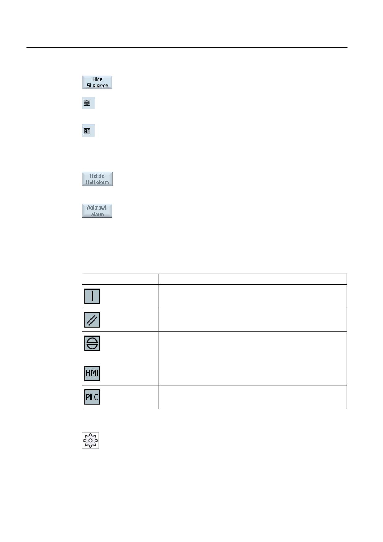
Acknowledgement symbols
Symbol
Meaning
Turn the unit off and back on (main switch), or press NCK POWER ON.
Press the <RESET> key.
Press the <ALARM CANCEL> key.
- OR -
Press the "Acknowl. HMI alarm" softkey.
Press the key provided by the manufacturer.
Machine manufacturer
Please refer to the machine manufacturer's specifications.
Universal
342
Operating Manual, 03/2013, 6FC5398-6AP40-3BA1
Alarm, error, and system messages
17.2 Displaying an alarm log
17.2
Displaying an alarm log
A list of all the alarms and messages that have occurred so far are listed in the "Alarm Log"
window.
Up to 500 administered, incoming and outgoing events are displayed in chronological order.
Machine manufacturer
Please refer to the machine manufacturer's specifications.
Procedure
1.
Select the "Diagnostics" operating area.
2.
Press the "Alarm log" softkey.
The "Alarm Log" window opens.
All of the coming and going events - that have occurred since the HMI
was started - are listed.
3.
Press the "Display new" softkey to update the list of displayed
alarms/messages.
4.
Press the "Save Log" softkey.
The log that is currently displayed is stored as text file alarmlog.txt in the
system data in directory card/user/sinumerik/hmi/log/alarm_log.
Universal
Operating Manual, 03/2013, 6FC5398-6AP40-3BA1
343
Alarm, error, and system messages
17.3 Displaying messages
17.3
Displaying messages
PLC and part program messages may be issued during machining.
These message will not interrupt the program execution. Messages provide information with
regard to a certain behavior of the cycles and with regard to the progress of machining and
are usually kept beyond a machining step or until the end of the cycle.
Overview of messages
You can display all issued messages.
The message overview contains the following information:
● Date
● Message number
is only displayed for PLC messages
● Message text
Procedure
1.
Select the "Diagnostics" operating area.
2.
Press the "Messages" softkey.
The "Messages" window appears.
Universal
344
Operating Manual, 03/2013, 6FC5398-6AP40-3BA1
Alarm, error, and system messages
17.4 Sorting, alarms, faults and messages
17.4
Sorting, alarms, faults and messages
If a large number of alarms, messages or alarm logs are displayed, you have the option of
sorting these in an ascending or descending order according to the following criteria:
● Date (alarm list, messages, alarm log)
● Number (alarm list, messages)
As a consequence, for every extensive lists, you can obtain the required information faster.
Procedure
1.
Select the "Diagnostics" operating area.
2.
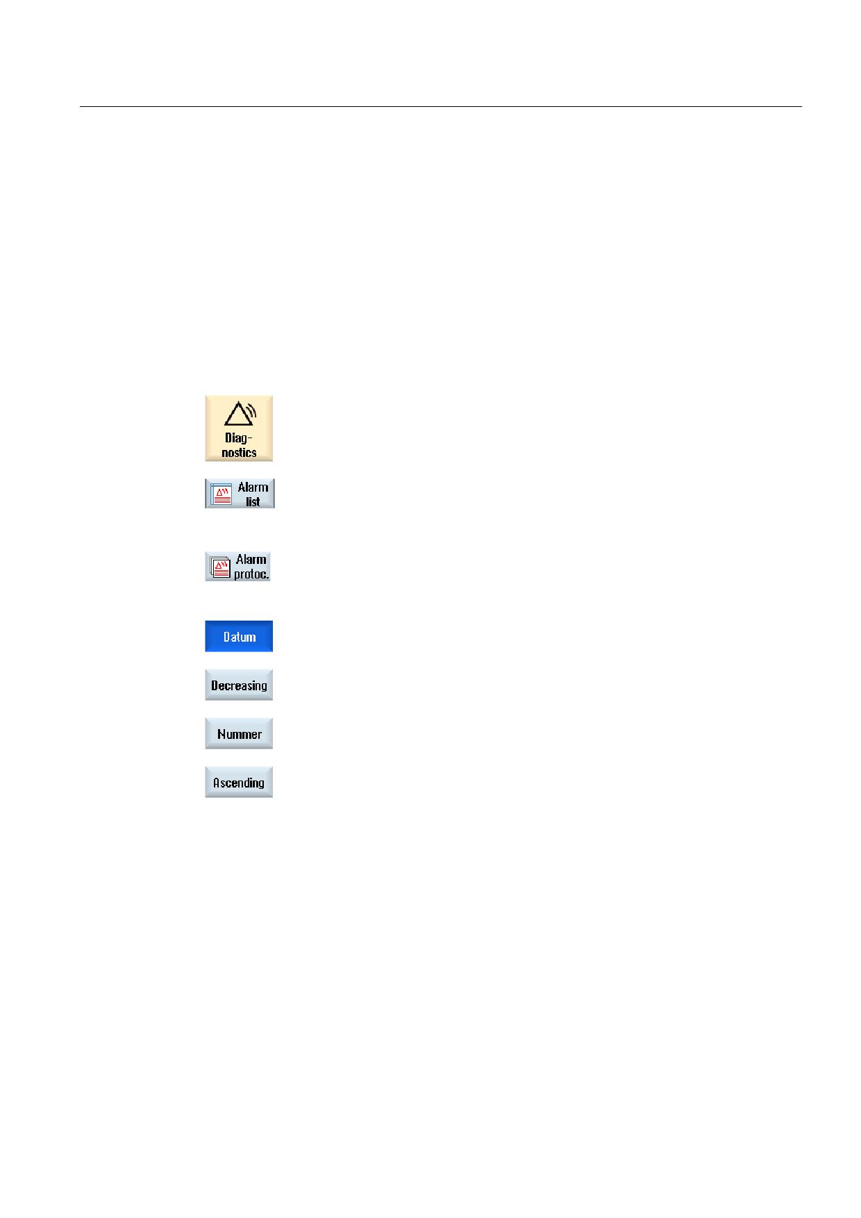
Press the softkey "Alarm list", "Messages" or "Alarm log" to display the
requested messages and alarms.
3.
Press the "Sort" softkey.
The list of entries is sorted in ascending order according to date, i.e. the
most recent information is at the end of the list.
4.
Press the softkey "Descending" to sort the list in a descending order.
The most recent event is shown at the beginning of the list.
5.
Press the "Number" softkey if you wish to sort the alarm list or the list
with messages according to numbers.
6.
Press the "Ascending" softkey if you wish to display the list in an
ascending order.
Universal
Operating Manual, 03/2013, 6FC5398-6AP40-3BA1
345
Alarm, error, and system messages
17.5 PLC and NC variables
17.5
PLC and NC variables
17.5.1
Displaying and editing PLC and NC variables
The "NC/PLC Variables" window allows NC system variables and PLC variables to be
monitored and changed.
You receive the following list in which you can enter the desired NC/PLC variables in order to
display the actual values.
● Variable
Address for NC/PLC variable.
Incorrect variables have a red backg0round and are displayed with a # character in the
value column.
● Comment
Any comment on the variable.
The columns can be displayed and hidden.
● Format
Specify the format in which the variable is to be displayed.
The format can be specified (e.g. floating point).
● Value
Displays the actual value of the NC/PLC variables.
PLC variables
Inputs
Input bit (Ex), input byte (EBx), input word (EWx), input double word (EDx)
Outputs
Output bit (Ax), output byte (ABx), output word (AWx), output double word
(ADx)
Bit memory
Memory bit (Mx), memory byte (MBx), memory word (MWx), memory
double word (MDx)
Times
Time (Tx)
Counters
Counter (Cx)
Data
Data block (DBx): Data bit (DBXx), data byte (DBBx), data word (DBWx),
data double word (DBDx)
Formats
B
Binary
H
Hexadecimal
D
Decimal without sign
+/-D
Decimal with sign
F
Floating point (for double words)
A
ASCII character
Universal
346
Operating Manual, 03/2013, 6FC5398-6AP40-3BA1
Alarm, error, and system messages
17.5 PLC and NC variables
Notation for variables
● PLC variables
EB2
A1.2
DB2.DBW2
● NC variables
- NC system variables - notation
$AA_IM[1]
- User variables/GUDs - notation
GUD/MyVariable[1,3]
- OPI - notation
/CHANNEL/PARAMETER/R[u1,2]
Note
NC system variables and PLC variables
• System variables can be dependent on the channel. When the channel is switched over,
the values from the corresponding channel are displayed.
• For user variables (GUDs) it is not necessary to make a specification according to global
or channel-specific GUDs. The indices of GUD arrays are, just like NC variables in the
system variable syntax, 0-based; this means that the first element starts with the index 0.
• Using the tooltip, for NC system variables, you can display the OPI notation (with the
exception of GUDs).
Changing PLC variables
Changes can only be made to the PLC variables with the appropriate password.
WARNING
Incorrect parameterization
Changes in the states of NC/PLC variables have a major impact on the machine. Incorrect
configuration of the parameters can endanger human life and cause damage to the
machine.
Universal
Operating Manual, 03/2013, 6FC5398-6AP40-3BA1
347
Alarm, error, and system messages
17.5 PLC and NC variables
Changing and deleting values
1.
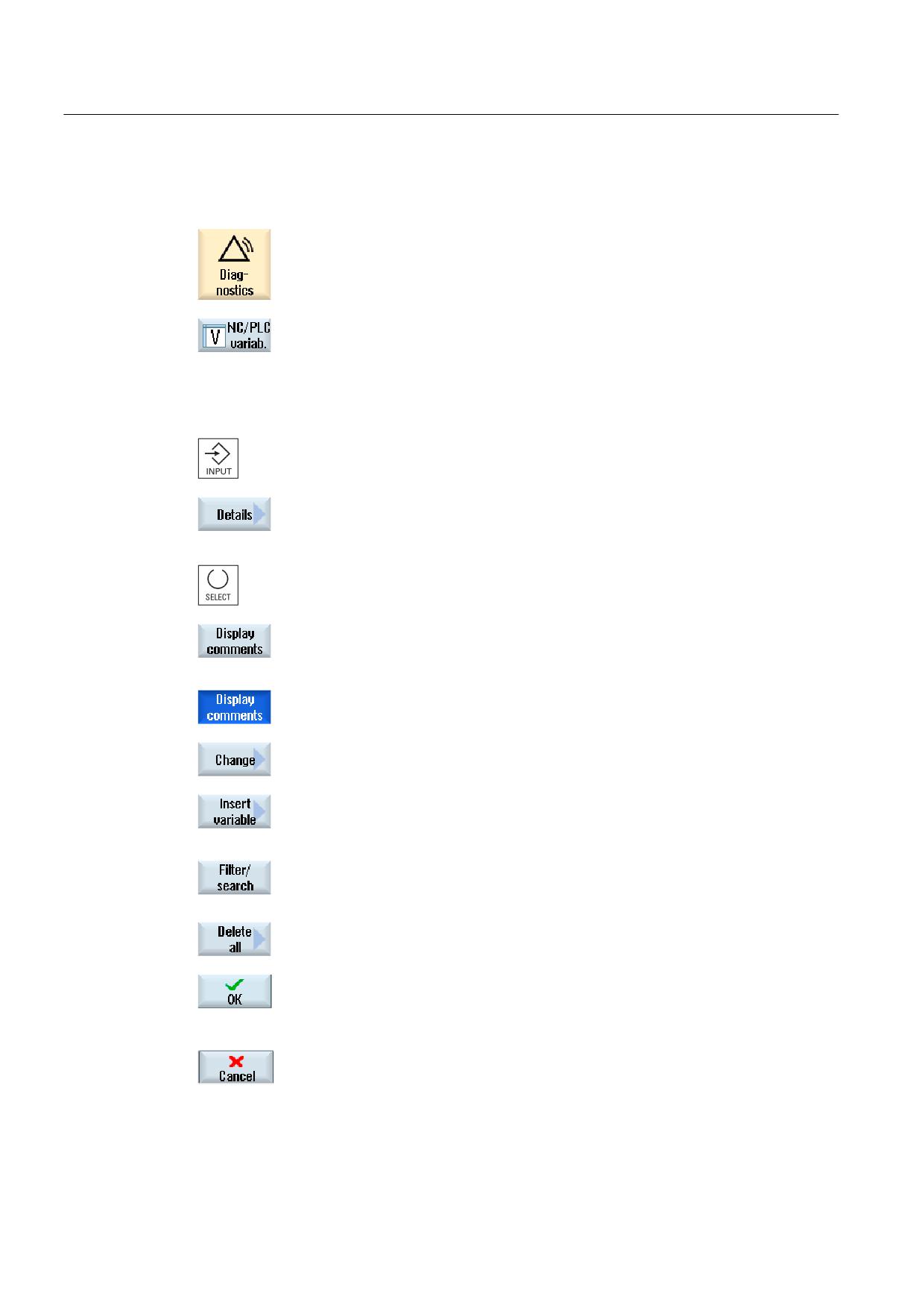
Select the "Diagnostics" operating area.
2.
Press the "NC/PLC variables" softkey.
The "NC/PLC Variables" window opens.
3.
Position the cursor in the "Variable" column and enter the required
variable.
4.
Press the <INPUT> key.
The operand is displayed with the value.
5.
Press the "Details" softkey.
The "NC/PLC Variables: Details" window opens. The information for
"Variable", "Comment" and "Value" is displayed in full length.
6.
Position the cursor in the "Format" field and choose the required format
with <SELECT>.
7.
Press the "Display comments" softkey.
The "Comments" column is displayed. You have the option of creating
comments or editing existing comments.
Press the "Display comments" softkey once again to hide the column.
8.
Press the "Change" softkey if you would like to edit the value.
The "Value" column can be edited.
9.
Press the "Insert variable" softkey if you wish to select a variable from a
list of all existing variables and insert this.
The "Select Variable" window opens.
10.
Press the "Filter/search" softkey to restrict the display of variables (e.g.
to mode group variables) using the "Filter" selection box and/or select
the desired variable using the "Search" input box.
Press the "Delete all" softkey if you would like to delete the entries for
the operands.
11.
Press the "OK" softkey to confirm the changes or the deletion.
- OR -
Press the "Cancel" softkey to cancel the changes.
Universal
348
Operating Manual, 03/2013, 6FC5398-6AP40-3BA1
Alarm, error, and system messages
17.5 PLC and NC variables
Note
"Filter/Search" when inserting variables
The start value for "Filter/Search" of variables differs.
For example, to insert the variable $R[0], set "Filter/Search":
• The start value is 0, if you filter according to "System variables".
• The start value is 1, if you filter according to "All (no filter)". In this case, all signals are
displayed and shown in the OPI notation.
Changing operands
Depending on the type of operand, you can increment or decrement the address by 1 place
at a time using the "Operand +" and "Operand -" softkeys.
Note
Axis names as index
For axis names, the softkeys "Operand +" and "Operand -" do not act as index, e.g. for
$AA_IM[X1].
Examples
DB97.DBX2.5
Result: DB97.DBX2.6
$AA_IM[1]
Result: $AA_IM[2]
MB201
Result: MB200
/Channel/Parameter/R[u1,3]
Result: /Channel/Parameter/R[u1,2]
Universal
Operating Manual, 03/2013, 6FC5398-6AP40-3BA1
349
Alarm, error, and system messages
17.5 PLC and NC variables
17.5.2
Saving and loading screen forms
You have the option of saving the configurations of the variables made in the "NC/PLC
variables" window in a screen form that you reload again when required.
Editing screen forms
If you change a screen form that has been loaded, then this is marked using with * after the
screen form name.
The name of a screen form is kept in the display after switching-off.
Procedure
1.
You have entered values for the desired variables in the "NC/PLC
variables" window.
2.
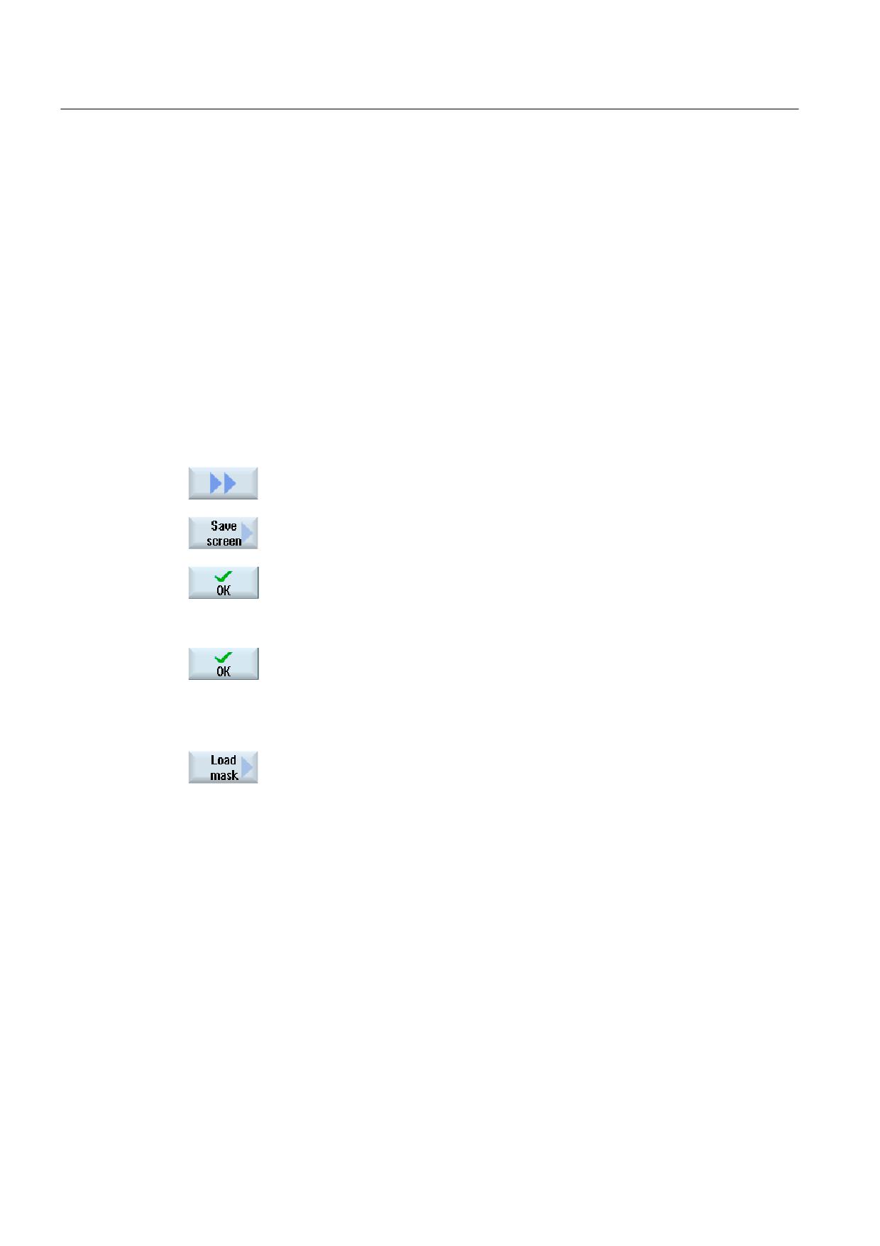
Press the ">>" softkey.
3.
Press the "Save screen" softkey.
The "Save screen: Select archiving" window opens.
4.
Position the cursor on the template folder for variable screen forms in
which your actual screen form should be saved and press the "OK"
softkey.
The "Save screen: Name" window opens.
5.
Enter the name for the file and press the "OK" softkey.
A message in the status line informs you that the screen form was
saved in the specified folder.
If a file with the same name already exists, they you will receive a
prompt.
6.
Press the "Load screen" softkey.
The "Load screen" window opens and displays the sample folder for the
variable screen forms.
7.
Select the desired file and press the "OK" softkey.
You return to the variable view. The list of all of the predefined NC and
PLC variables is displayed.
Universal
350
Operating Manual, 03/2013, 6FC5398-6AP40-3BA1
Alarm, error, and system messages
17.5 PLC and NC variables
17.5.3
Load symbols
PLC data can also be edited via symbols.
To do this, the symbol tables and texts for the symbols in the PLC project must have been
suitably prepared (STEP7) and made available in SINUMERIK Operate.
Preparing PLC data
Save the generated files in the /oem/sinumerik/plc/symbols directory.
Procedure
1.
The variable view is opened.
2.
Press the ">>" and "Load icons" softkeys.
The "Import PLC symbols: *.snh" window opens.
3.
In the folder "/oem/sinumerik/plc/symbols", select the "PlcSym.snh" file
to import the symbols and then click on "OK".
4.
In the folder "/oem/sinumerik/plc/symbols", select the "PlcSym.snt" file
to import the symbols and then press the "OK" softkey.
You will obtain an appropriate note if the tables were successfully
imported.
5.
Press the "OK" softkey.
You return to the "NC/PLC variables" window.
6.
Restart the SINUMERIK Operate in order to activate the files.
Universal
Operating Manual, 03/2013, 6FC5398-6AP40-3BA1
351

Alarm, error, and system messages
17.6 Creating screenshots
17.6
Creating screenshots
You can create screenshots of the current user interface.
Each screenshot is saved as a file and stored in the following folder:
/user/sinumerik/hmi/log/screenshot
Procedure
Ctrl + P Press the <Ctrl+P> key combination.
A screenshot of the current user interface is created in .png format.
The file names assigned by the system run in ascending order from
"SCR_SAVE_0001.png" to "SCR_SAVE_9999". You can create up to 9,999
screenshots.
Copy file
1.
Select the "Start-up" operating area.
2.
Press the "System data" softkey and open the specified folder.
As you cannot open screenshots in SINUMERIK Operate, you must
copy the files to a Windows PC either via "WinSCP" or via a USB-
FlashDrive.
You can open the files using a graphics program, e.g. "Office Picture
Manager".
Universal
352
Operating Manual, 03/2013, 6FC5398-6AP40-3BA1
Alarm, error, and system messages
17.7 Version
17.7
Version
17.7.1
Displaying version data
The following components with the associated version data are specified in the "Version
data" window:
● System software
● Basic PLC program
● PLC user program
● System extensions
● OEM applications
● Hardware
Information is provided in the "Nominal version" column as to whether the versions of the
components deviate from the version supplied on the CompactFlash Card.
The version displayed in the "Actual version" column matches the version of
the CF card.
The version displayed in the "Actual version" column does not match the
version of the CF card.
You may save the version data. Version displays saved as text files can be further
processed as required or sent to the hotline in the event of an error.
Procedure
1.
Select the "Diagnosis" operating area.
2.
Press the "Version" softkey.
The "Version Data" window appears.
Data from the available components are displayed.
3.
Select the component for which you would like more information.
Universal
Operating Manual, 03/2013, 6FC5398-6AP40-3BA1
353
Alarm, error, and system messages
17.7 Version
4.
Press the "Details" softkey, in order to receive more exact information
on the components displayed.
17.7.2
Save information
All the machine-specific information of the control is combined in a configuration via the user
interface. You can save machine-specific information on the drives that have been set-up.
Procedure
1.
Select the "Diagnostics" operating area.
2.
Press the "Version" softkey.
It takes some time to call the version display. While the version data is
being determined a progress message box and the appropriate text are
displayed in the dialog line.
3.
Press the "Save" softkey.
The "Save Version Information: Select Archive" window opens. The
following storage locations are offered depending on the configuration:
• Local drive
• Network drives
• USB
• Version data (archive: Data tree in the "HMI data" directory)
4.
Then press the "New directory" softkey if you wish to create your own
directory.
5.
Press the "OK" softkey. The directory is created.
6.
Press the "OK" softkey again to confirm the storage location.
Universal
354
Operating Manual, 03/2013, 6FC5398-6AP40-3BA1
Alarm, error, and system messages
17.7 Version
The "Save Version Information: Name" window opens. The following
options are available:
• In the "Name:" text field, the file name is pre-assigned with <Machine
name/no.>+<CF-card number>. "_config.xml" or "_version.txt" is
automatically attached to the file names.
• In text field "Comment", you can add a comment that is stored with
the configuration data.
Select the following data via a checkbox:
• Version data (.TXT): Output of pure version data in text format.
• Configuration data (.XML): Output of configuration data in XML
format. The configuration file contains the data you entered under
Machine identity, the license requirements, the version information
and the logbook entries.
7.
Press the "OK" softkey to start the data transfer.
See also
Logbook (Page 356)
Universal
Operating Manual, 03/2013, 6FC5398-6AP40-3BA1
355
Alarm, error, and system messages
17.8 Logbook
17.8
Logbook
The logbook provides you with the machine history in an electronic form.
If service is carried out on the machine, this can be electronically saved. This means that it is
possible to obtain a picture about the "History" of the control and to optimize service.
Editing the logbook
You can edit the following information:
● Editing information on the machine identity
- Machine name/No.
- Machine type
- Address data
● Make logbook entries (e.g. "filter replaced")
● Deleting logbook entries
Note
Deleting logbook entries
Up to the 2nd commissioning, you have the option to delete all of the entered data up to
the time of the first commissioning.
Output of the logbook
You have the possibility of exporting the logbook by generating a file using the "Save
version" function in which the logbook is contained as section.
See also
Save information (Page 354)
Universal
356
Operating Manual, 03/2013, 6FC5398-6AP40-3BA1
Alarm, error, and system messages
17.8 Logbook
17.8.1
Displaying and editing the logbook
Procedure
1.
Select the "Diagnostics" operating area.
2.
Press the "Version" softkey.
3.
Press the "Logbook" softkey.
The "Machine logbook" window opens.
Editing end customer data
You have the option of changing the address data of the end customer
using the "Change" softkey.
- OR -
Using the "Clean up" softkey, you can delete all logbook entries.
All entries, except the date of the first commissioning, are deleted and
the softkey "Clean up" is deactivated.
Note
Deleting logbook entries
As soon as the 2nd commissioning has been completed, the "Clean up" softkey to delete the
logbook data is no longer available.
Universal
Operating Manual, 03/2013, 6FC5398-6AP40-3BA1
357
Alarm, error, and system messages
17.8 Logbook
17.8.2
Making a logbook entry
Using the "New logbook entry" window to make a new entry into the logbook.
Enter your name, company and department and a brief description of the measure taken or a
description of the fault.
Note
If you wish to make line breaks in the "fault diagnostics/measure" field, use the key
combination <ALT> + <INPUT>.
The date and entry number are automatically added.
Sorting the entries
The logbook entries are displayed numbered in the "machine logbook" window.
More recent entries are always added at the top in the display.
Procedure
1.
The logbook is opened.
2.
Press the "New entry" softkey.
The "New logbook entry" window opens.
3.
Enter the required data and press the "OK" softkey.
You return to the "Machine logbook" window and the entry is displayed
below the machine identity data.
Note
Deleting logbook entries
Up to the end of the 2nd commissioning, you have the option to delete the logbook entries
up to the time of the first commissioning using the "Clean up" softkey.
Universal
358
Operating Manual, 03/2013, 6FC5398-6AP40-3BA1
Alarm, error, and system messages
17.8 Logbook
Searching for a logbook entry
You have the option for searching for specific entries using the search function.
1.
The "Machine logbook" window is opened.
2.
Press the "Search..." softkey and enter the desired term in the search
form. You can make a search according to date/time, company
name/department or according to fault diagnostics/measure.
The cursor is positioned on the first entry that corresponds to the search
term.
3.
Press the "Continue search" softkey if the entry found is not the one that
you are looking for.
Additional search option
Press the "Go to Beginning" softkey to start the search at the latest
entry.
Press the "Go to End" softkey to start the search at the oldest entry.
Universal
Operating Manual, 03/2013, 6FC5398-6AP40-3BA1
359
Alarm, error, and system messages
17.9 Remote diagnostics
17.9
Remote diagnostics
17.9.1
Setting remote access
You can influence the remote access to your control in the "Remote diagnostics (RCS)"
window.
Here, rights for all types of remote control are set. The selected rights are defined from the
PLC and using the setting at the HMI.
The HMI can restrict the rights specified from the PLC, but however, cannot extend the rights
beyond the PLC rights.
If the settings made permit access from outside, then this is still dependent on a manual or
automatic confirmation.
Rights for remote access
The "Specified from PLC" field shows the access rights for remote access or remote
monitoring specified from the PLC.
Machine manufacturer
Please refer to the machine manufacturer's specifications.
In the "Selected in the HMI" selection box, you have the possibility of setting rights for
remote control:
● Do not permit remote access
● Permit remote monitoring
● Permit remote control
The combination of the settings in the HMI and in the PLC show the valid status as to
whether access is permitted or not. This is displayed in the "Resulting from" line.
Settings for the confirmation dialog box
If the settings made for "Specified from the PLC" and "Selected in the HMI" permit access
from outside, then this is however, still dependent on either a manual or automatic
confirmation.
As soon as a remote access is permitted, at all of the active operating stations, a query
dialog box is displayed for the operator at the active operating station to either confirm or
reject an access.
For the case that there is no local operation, then the control behavior can be set for this
particular scenario. You define how long this window is displayed and whether, after the
confirmation has expired, the remote access is automatically rejected or accepted.
Universal
360
Operating Manual, 03/2013, 6FC5398-6AP40-3BA1
Alarm, error, and system messages
17.9 Remote diagnostics
Display of the state
Remote monitoring active
Remote control active
If remote access is active, using these icons you will be informed in the status line as to
whether a remote access is presently active or whether only monitoring is permitted.
Procedure
1.
Select the "Diagnostics" operating area.
2.
Press the "Remote diag." softkey.
The "Remote diagnostics (RCS)" window is opened.
3.
Press the "Change" softkey.
The "Selected in the HMI" is activated.
4.
If you desire remote control, select the entry "Permit remote control".
In order that remote control is possible, the entry "Permit remote
control" must be specified in the fields "Specified from the PLC" and
"Selected in the HMI".
5.
Enter new values in the group "Behavior for confirming remote access"
if you wish to change the behavior for confirming remote access.
6.
Press the "OK" softkey.
The settings are accepted and saved.
References
For a description of configuration options, refer to the
Commissioning Manual SINUMERIK Operate (IM9) / SINUMERIK 840D sl
Universal
Operating Manual, 03/2013, 6FC5398-6AP40-3BA1
361
Alarm, error, and system messages
17.9 Remote diagnostics
17.9.2
Permit modem
You can permit remote access to your control via a teleservice adapter IE connected at
X127.
Machine manufacturer
Please refer to the machine manufacturer's specifications.
Software option
You need the "MC Information System RCS Host" option to display the
"Permit modem" softkey.
Procedure
1.
The "Remote diagnostics (RCS)" window is opened.
2.
Press the "Permit modem" softkey.
Access to the control via modem is enabled so that a connection can be
established.
3.
To block access again, press the "Permit modem" softkey again.
Universal
362
Operating Manual, 03/2013, 6FC5398-6AP40-3BA1
Alarm, error, and system messages
17.9 Remote diagnostics
17.9.3
Request remote diagnostics
Using the "Request remote diagnostics" softkey, from your control you have the option of
actively requesting remote diagnostics with your machinery construction OEM.
The access via modem must be enabled if the access is to be made via modem.
Machine manufacturer
Please refer to the machine manufacturer's specifications.
When requesting remote diagnostics, you obtain a window with the corresponding pre-
assigned data and values of the ping service. If required, you can ask your machine
manufacturer for this data.
Data
Meaning
IP address
IP address of the remote PC
Port
Standard port that is intended for remote diagnostics
Send duration
Duration of the request in minutes
Send interval
Cycle in which the message is sent to the remote PC in seconds
Ping send
Message for the remote PC
data
Procedure
1.
The "Remote diagnostics (RCS)" window is opened.
2.
Press the "Request remote diagnostics" softkey.
The "Request remote diagnostics" window is displayed.
3.
Press the "Change" softkey if you would like to edit the values.
4.
Press the "OK" softkey.
The request is sent to the remote PC.
References
Commissioning Manual SINUMERIK Operate (IM9) / SINUMERIK 840D sl
See also
Permit modem (Page 362)
Universal
Operating Manual, 03/2013, 6FC5398-6AP40-3BA1
363
Alarm, error, and system messages
17.9 Remote diagnostics
17.9.4
Exit remote diagnostics
Procedure
1.
The "Remote diagnostics (RCS)" is opened and it is possible that
remote monitoring or remote access is active.
2.
Block the modem access if access via modem is to be blocked.
- OR -
In the "Remote Diagnostics (RCS)" window, reset the access rights to
"Permit no remote access".
See also
Permit modem (Page 362)
Setting remote access (Page 360)
Universal
364
Operating Manual, 03/2013, 6FC5398-6AP40-3BA1
Appendix
A
A.1
840D sl documentation overview
6,180(5,.
' VO GRFXPHQWDWLRQ RYHUYLHZ
*HQHUDO GRFXPHQWDWLRQ
6,180(5,.
' VO
6DOHV EURFKXUH
&DWDORJ 1&
&DWDORJ 30
6,027,21
6,1$0,&6 6
DQG PRWRUV
IRU SURGXFWLRQ PDFKLQHV
8VHU GRFXPHQWDWLRQ
6,180(5,.
6,180(5,.
6,180(5,.
6,180(5,.
' VO
' VO
' VO
' VO
'
'
'
6,1$0,&6
6
2SHUDWLQJ 0DQXDO
3URJUDPPLQJ PDQXDO
3URJUDPPLQJ PDQXDO
'LDJQRVWLFV PDQXDO
ದ 8QLYHUVDO
ದ )XQGDPHQWDOV
ದ ,62 WXUQLQJ
ದ 7XUQLQJ
ದ -RE SODQQLQJ
ದ ,62 PLOOLQJ
ದ 0LOOLQJ
ದ 0HDVXULQJ F\FOHV
0DQXIDFWXUHU VHUYLFH GRFXPHQWDWLRQ
6,180(5,.
6,180(5,.
6,180(5,.
6,180(5,.
6,180(5,.
' VO
' VO
' VO
' VO
' VO
'
6,1$0,&6
6,1$0,&6
6
6
'HYLFH PDQXDO
6\VWHP PDQXDO
6\VWHP PDQXDO
&RPPLVVLRQLQJ PDQXDO
/LVW PDQXDO
ದ 1&8
*XLGHOLQHV IRU WKH PDFKLQH
&WUO (QHUJ\
ದ &1& 1&. 3/&
ದ 0DFKLQH GDWD
ದ RSHUDWRU FRPSRQHQWV
FRQILJXUDWLRQ
'ULYH
ದ ,QWHUIDFH VLJQDOV
DQG QHWZRUNLQJ
ದ %DVH VRIWZDUH DQG
ದ 9DULDEOHV
RSHUDWLQJ VRIWZDUH
0DQXIDFWXUHU VHUYLFH GRFXPHQWDWLRQ
6,180(5,.
6,180(5,.
6,1$0,&6
6,180(5,.
6,180(5,.
' VO
' VO
6
' VO
'
)XQFWLRQ PDQXDO
)XQFWLRQ PDQXDO
)XQFWLRQ PDQXDO
)XQFWLRQ PDQXDO
&RQILJXUDWLRQ PDQXDO
ದ %DVLF IXQFWLRQV
7RRO PDQDJHPHQW
'ULYH IXQFWLRQV
6DIHW\ ,QWHJUDWHG
(0& 'HVLJQ *XLGHOLQHV
ದ ([WHQGHG IXQFWLRQV
ದ 6SHFLDO IXQFWLRQV
ದ 6\QFKURQRXV DFWLRQV
ದ ,62 GLDOHFWV
,QIR WUDLQLQJ
(OHFWURQLF GRFXPHQWDWLRQ
6,180(5,.
6,180(5,.
'2&RQ&'
0\ 'RFXPHQWDWLRQ
,QGXVWU\ 0DOO
0DQDJHU
7UDLQLQJ GRFXPHQWV
0DQXDOV
ದ 6LPSOH PLOOLQJ
7RRO DQG
ZLWK 6KRS0LOO
PROG PDNLQJ
ದ 6LPSOH WXUQLQJ
ZLWK 6KRS7XUQ
Universal
Operating Manual, 03/2013, 6FC5398-6AP40-3BA1
365