содержание .. 1 2 3 4 ..
DoorHan Электромеханические приводы для ворот и дверей. Руководства по монтажу и эксплуатации - часть 3

ЭЛЕКТРИЧЕСКИЕ ПОДКЛЮЧЕНИЯ
2.
Схема подключения электромеханического замка мощностью до 3А
J1
5 А
M1
M2
J7
FOTO
J4
J3
COM OP CL
COM OP CL
LAMP S-B-S PED OP CL COM STOP
+24V S
Lock
PE N L
1
2
3
4 5
6 7 8
9 10 11 12 13 14 15 16 17 18 19
20 21
3.
Схема подключения электромеханического замка мощностью свыше 3А
Для подключения электромеханического замка необходимо использовать промежуточное реле с техническими харак-
теристиками:
напряжение питания — 24 VDC;
коммутируемый ток — 10 А.
J1
5 А
M1
M2
J7
FOTO
J4
J3
COM OP CL
COM OP CL
LAMP S-B-S PED OP CL COM STOP
+24V S
Lock
PE N L
1
2
3
4 5
6 7 8
9 10 11 12 13 14 15 16 17 18 19
20 21
24 V 10 A
Трансформатор
220 × 12 V 40 W
~ 220 V
50 Hz
4.
Схема подключения индикаторного света освещения
J1
5 А
M1
M2
J7
J4
J3
FOTO
COM OP CL
LAMP S-B-S PED OP CL COM STOP
+24V S
COM OP CL
Lock
PE N L
1
2
3
4 5
6 7 8
9 10 11 12 13 14 15 16 17 18 19
20 21
24 VDC 5 W
4

ЭЛЕКТРИЧЕСКИЕ ПОДКЛЮЧЕНИЯ
5.
Схема подключения дополнительного освещения
Для подключения дополнительного освещения необходимо использовать промежуточное реле с техническими харак-
теристиками:
напряжение питания — 24 VDC;
коммутируемый ток — 10 А.
J1
5 А
M1
M2
J7
J4
FOTO
J3
COM OP CL
COM OP CL
LAMP S-B-S PED OP CL COM STOP
+24V S
Lock
PE N L
1
2
3
4 5
6 7 8
9 10 11 12 13 14 15 16 17 18 19
20 21
24 VDC 10 A
~ 220 V
50 Hz
6.
Схема подключения дополнительного светофора
Для подключения дополнительного освещения необходимо использовать промежуточное реле с техническими харак-
теристиками:
напряжение питания — 24 VDC;
коммутируемый ток — 10 А.
ПРИМЕЧАНИЕ:
Включение сигнальной клеммы (S) в режиме светофора см. таблицу базового программирования.
J1
5 А
M1
M2
J7
J4
J3
FOTO
COM OP CL
LAMP S-B-S PED OP CL COM STOP
+24V S
COM OP CL
Lock
PE N L
1
2
3
4 5
6 7 8
9 10 11 12 13 14 15 16 17 18 19
20 21
24 VDC 10 A
красный
~ 220 V
зеленый
50 Hz
5
ПРОГРАММИРОВАНИЕ ПРИВОДА
2. ПРОГРАММИРОВАНИЕ ПРИВОДА
2.1. БАЗОВОЕ ПРОГРАММИРОВАНИЕ
Для базового программирования выполните следующие действия:
1. Войдите в меню базового программирования, нажав кнопку «P». В левой части дисплея отобразится «P», в правой
части — номер пункта меню согласно таблице программирования (см. таблицу базового программирования).
2. Нажимая кнопку «+» или «-», выберите требуемый пункт меню.
3. Для входа в пункт меню нажмите «P», после чего на дисплее начнет мигать значение настраиваемого параметра.
4. Нажатием кнопок «+» и «-» измените значение настраиваемого параметра.
5. Для сохранения нового значения и выхода в основное меню нажмите «P».
6. После настройки всех интересующих параметров нажмите кнопку «R» для выхода из меню программирования.
ПРИМЕЧАНИЕ:
При необходимости выйти в основное меню без сохранения параметров нажмите «R».
Пункт меню
Описание функции
По умолчанию
Выбор режима работы с приводами:
P0
n
Y — по времени; n — по концевым выключателям
Задержка на закрывание 1-ой створки:
P1
1 — 1 сек.; 2 — 5 сек.; 3 — 10 сек.; 4 — 15 сек.; 5 — 20 сек.; 6 — 25 сек.; 7 — 30 сек.; 8 — 35 сек.;
2
9 — 40 сек.
Задержка на открывание 2-ой створки:
P2
2
1 — 1 сек.; 2 — 2 сек.; 3 — 3 сек.; 4 — 4 сек.; 5 — 5 сек.
P3
Настройка работы платы управления (усилия, замедления и времени работы)
Ln
Функция автоматического закрытия ворот:
P4
0 — выключено; 1 — через 10 сек.; 2 — через 20 сек.; 3 — через 30 сек.; 4 — через 60 сек.; 5 — через 90 сек.;
0
6 — через 120 сек.; 7 — через 180 сек.; 8 — через 360 сек.; 9 — через 420 сек.
Дополнительное освещение (клеммы 19-20):
0 — мигание во время закрытия, вкл. во время открытия.
Включение во время любого движения и выключение после остановки: 1 — через 10 сек.; 2 — через 20 сек.;
P5
3 — через 30 сек.; 4 — через 60 сек.; 5 — через 90 сек.; 6 — через 120 сек.; 7 — через 180 сек.; 8 — через
0
360 сек.
9 — режим светофора включается только в открытом положении на концевых выключателях (не работает в
режиме без концевых выключателей)
P6
Счетчик количества циклов (одно деление — 1 000 циклов)
00
2.2. НАСТРОЙКА РАБОТЫ ПРИВОДА
Процесс обучения зависит от выбранного режима работы (пункт меню «P0»).
Режим работы с концевыми выключателями:
1. Установить створки в закрытое положение и привести привода в заблокированное состояние (при наличии при-
твора настроить задержку створок).
2. Зайти в меню базового программирования (см. раздел «Базовое программирование») и выбрать пункт «P3».
3. Нажать кнопку «P». Створка 1 начнет движение на открытие и на дисплее замигает надпись «Ln».
4. Если требуется настроить замедление, нажмите кнопку «+» во время движения створки.
5. После цикла открытия и закрытия створок, прозвучит два коротких сигнала и программа автоматически выйдет
из режима программирования.
Режим работы по времени (по умолчанию):
1. Установить створки в закрытое положение и привести привода в заблокированное состояние (при наличии при-
твора настроить задержку створок).
2. Зайти в меню базового программирования (см. раздел «Базовое программирование») и выбрать пункт «P3».
3. Нажать кнопку «P». Створка 1 начнет движение на открытие и на дисплее замигает надпись «Ln».
4. По нажатию кнопки «+» створка начнет замедляться.
5. Второе нажатие кнопки «+» остановит створку 1. Если настроен режим автоматизации одностворчатых ворот
(см. раздел «Расширенное программирование»), начнется выполнение пункта 12.
6. Створка 2 начнет движение на открытие.
7. По нажатию кнопки «+» створка начнет замедляться.
6

ПРОГРАММИРОВАНИЕ ПРИВОДА
8. Второе нажатие кнопки «+» остановит створку 2.
9. Створка 2 начнет движение на закрытие.
10. По нажатию кнопки «+» створка начнет замедляться.
11. Второе нажатие кнопки «+» остановит створку 2.
12. Створка 1 начнет движение на закрытие.
13. По нажатию кнопки «+» створка начнет замедляться.
14. Второе нажатие кнопки «+» остановит створку 1.
15. Прозвучит два коротких сигнала и программа автоматически выйдет из режима программирования.
ПРИМЕЧАНИЕ:
При срабатывании устройств безопасности на дисплее начнет мигать надпись «Er» (Error — «ошибка»). Устра-
ните причину ошибки и произведите повторное обучение.
ПРИМЕЧАНИЕ:
Для настройки движения створки без замедления по достижении нужного времени работы нажмите кнопку «+»
два раза.
2.3. ИНДИКАЦИЯ ДИСПЛЕЯ
Дисплей состоит из двух семисегментных индикаторов.
С их помощью отображается состояние коммутации контактов на плате управления и ворот, которыми она управляет.
Индикатор
Сегмент
Описание
0
Светится когда контакт «FOTO OP» замкнут
1
Не используется
2
Не используется
3
Светится когда контакт «FOTO CL» замкнут
0
4
Светится когда контакт «PED» замкнут
5
Светится когда контакт «SBS» замкнут
6
Светится когда контакт «STOP» замкнут
7
Не используется
0
1
2
3
Индикация работы процессора
1
4
(переключение сегментов по часовой стрелке)
5
6
7
7

ПРОГРАММИРОВАНИЕ ПРИВОДА
2.4. РАСШИРЕННОЕ ПРОГРАММИРОВАНИЕ
Для выполнения расширенного программирования выполните следующие действия:
1. Для входа в расширенное программирование нажмите и удерживайте кнопку «P» в течение 10 сек. В левой части
дисплея появится «0», в правой части — номер пункта меню (см. таблицу расширенного программирования).
2. Нажимая кнопки «+» или «-» выберите требуемый пункт меню.
3. Для входа в пункт меню нажмите «P», после чего на дисплее начнет мигать значение настраиваемого параметра.
4. Нажатием кнопок «+» или «-» измените значение настраиваемого параметра.
5. Для сохранения нового значения и выхода в основное меню нажмите «P».
6. После настройки всех интересующих параметров для выхода из меню программирования нажмите кнопку «R».
ПРИМЕЧАНИЕ:
При необходимости выйти в основное меню без сохранения параметров нажмите «R».
Пункт
Описание функции
По умолчанию
меню
Режим автоматизации калитки или одностворчатых ворот:
0.0
n
Y — функция включена; n — функция выключена
Усилие на 1-й створке:
0.1
3
1 — минимальное усилие; 6 — максимальное усилие
Усилие на 2-й створке:
0.2
3
1 — минимальное усилие; 6 — максимальное усилие
Максимальное усилие в начальный момент времени:
0.3
n
Y — функция включена; n — функция выключена
Предварительное включение сигнальной лампы (5 сек.):
0.4
n
Y — функция включена; n — функция выключена
Выбор логики работы клеммы (19-21) для электрозамка:
0.5
n
Y — элетромагнитный; n — электромеханический
Режим срабатывания фотоэлементов на закрытие:
0.6
n
Y — реверс после освобождения проема; n — мгновенный реверс
Функция автоматического закрытия ворот после срабатывания фотоэлементов:
0.7
n
Y — функция включена; n — функция выключена
Логика открытия/закрытия ворот по удержанию кнопок (пульт не работает):
0.8
n
Y — функция включена; n — функция выключена
Функция запрета приема управляющих команд при движении ворот на открытие:
0.9
n
Y — функция включена; n — функция выключена
Логика раздельного управления:
кнопка S-B-S — открытие ворот и останов;
1.0
n
кнопка PED — закрытие ворот и останов;
Y — функция включена; n — функция выключена
Время открытия первой створки по кнопке PED:
1.1
0
0 - функция неактивна; 1 - 3 сек; 2 - 4 сек; 3 - 5 сек; 4 - 8 сек; 5 - 15 сек; 6 - 20 сек; 7 - 25 сек; 8 - 30 сек; 9 - 40 сек.
Удаленое программирование:
1.2
Y
Y - удаленное программирование разрешено; n - запрещено.
9.8
Сброс параметров на заводские настройки
rE
9.9
Версия программного обеспечения
2.5. СБРОС ПАРАМЕТРОВ НА ЗАВОДСКИЕ НАСТРОЙКИ
Для сброса параметров платы управления на заводские настройки войдите в расширенное программирование, выбе-
рите пункт «9.8», нажмите кнопку «P». На дисплее отобразится «rE», нажмите и удерживайте кнопку «P» в течение пяти
секунд. На дисплее перестанет мигать «rE» и плата перезагрузится, раздастся короткий звуковой сигнал. После проде-
ланной операции все настройки будут по умолчанию.
ПРИМЕЧАНИЕ:
При сбросе на заводские настройки память приемника не очищается.
8

ПРОГРАММИРОВАНИЕ ПУЛЬТОВ ДУ
3. ПРОГРАММИРОВАНИЕ ПУЛЬТОВ ДУ
3.1. ОЧИСТКА ПАМЯТИ ПРИЕМНИКА
После включения питания нажмите и удерживайте кнопку «R» в течение 20 секунд, после чего раздастся длинный
звуковой сигнал и программа выйдет в рабочий режим.
3.2. ЗАПИСЬ ПУЛЬТОВ DOORHAN В ПРИЕМНИК
Для записи пульта дистанционного управления необходимо нажать и удерживать кнопку «R», отпустить после того,
как на дисплее появятся два ноля «00». Затем выберите на пульте управления кнопку, которой впоследствии будете
управлять работой блока, и нажмите ее два раза. Раздастся короткий звуковой сигнал, что означает успешную запись
пульта в память приемника, на дисплее отобразится количество записанных в приемник пультов. Дождитесь автомати-
ческого выхода в рабочий режим. Для записи нескольких пультов повторите процедуру записи кода для каждого пульта.
Таким образом в память приемника можно записать до 60 пультов.
ПРИМЕЧАНИЕ:
Появилась возможность записи многоканальных пультов, позволяющая раздельно управлять открытием и
закрытием.
В отсутствие команд управления выход из режима записи пультов происходит автоматически через 20 сек
простоя.
При отключении блока управления от сети запрограммированные данные сохраняются в памяти.
При переполнении памяти приемника раздастся 3 длинных звуковых сигнала.
3.3. УДАЛЕННОЕ ПРОГРАММИРОВАНИЕ ПУЛЬТОВ DOORHAN
Пункты 1-4 необходимо выполнить в пятисекундном интервале:
1. Нажать и удерживать кнопку 2 (см. рисунок ниже) запрограммированного пульта.
2. Не отпуская нажатую кнопку 2, нажать и удерживать кнопку 1.
3. Отпустить зажатые кнопки.
4. Нажать запрограммированную кнопку пульта, приемник войдет в режим программирование пультов.
5. На новом пульте управления дважды нажать на кнопку, которой впоследствии будете управлять приводом.
Раздастся короткий звуковой сигнал, что означает успешную запись пульта в память приемника, на дисплее отобра-
зится количество записанных в приемник пультов, например, «01».
1
1
1
3
4
3
4
2
1
2
2
2
ПРИМЕЧАНИЕ:
Программирование пультов необходимо выполнять в радиусе действия приемника электропривода.
Номер кнопки можно определить по точкам на корпусе пульта.
9

ELECTRICAL CONNECTIONS
1. ELECTRICAL CONNECTIONS
WARNING!
The cable wires shall be protected from contact with any rough and sharp details. Before attempting any work on the
control board (connections, maintenance), always turn off power.
1.1. CONTROL UNIT WIRING DIAGRAM
0,8 А
Transformer
R
+
P
-
5 А
M1
M2
FOTO
COM OP CL
COM OP CL
LAMP S-B-S PED
OP CL COM STOP
+24V
S Lock
PE N L
1
2
3
4 5
6 7 8
9 10 11 12
13 14 15 16 17 18 19
20 21
NC
Photocells
(Normally
closed)
R
2
COM
GND
3
1
COM
NO
NC
GND
М1
М2
4
VCC
2
VCC
+24
4
5
Key-button
+2
220-240 V
50 Hz
1.2. CONTROL UNIT TERMINALS
1.
Power input connectors (J1 terminal block)
~220-240 V. PE, N, L — power supply connectors.
PE — ground terminal
N — power (neutral)
L — power (line)
2.
Electric motors and signal lamp connectors (J7 terminal block):
1-2-3. M1 (COM/OP/CL terminals) — connector for the first electric motor. It can be used for opening of one leaf (if a pass
door or one-leaf gate is automated).
4-5-6. M2 (COM/OP/CL terminals) — connector for the second electric motor. It cannot be used for opening of one leaf.
7-8. LAMP — output for signal lamp connection (230V~ 40 W max).
3.
Connectors for accessories (J4 terminal block (9—19 terminals) and J3 terminal block (20—21 terminals))
9-10. S-B-S — «Full opening» command: closing the contacts of the device connected to these terminals results in total open-
ing and/or closing of two gate leaves.
To install several devices connect their NO contacts in parallel.
11-12. PED — «Pedestrian passage» or «Close» command: closing the contacts of the device connected to these terminals
results in step-by-step opening or closing of one gate leaf.
10

ELECTRICAL CONNECTIONS
To install several devices connect their N.O. contacts in parallel.
13-15. OP FOTO — opening safety devices contact (NC): the purpose of this contact is to prevent people, animals and foreign
items from jamming during gate opening. If the opening safety devices are engaged when the drive is operating then they stop
the gate movement.
If the opening safety devices are engaged when the gate is closed then they prevent any gate movement.
WARNING!
If no devices are connected to these terminals install a jumper between the contacts 13-15.
14-15. CL FOTO — closing safety devices contact (NC): the purpose of this contact is to prevent people, animals and foreign
items from jamming during gate closing. If the closing safety devices are engaged when the drive is operating then the safety
devices reverse the movement of the gate, or stop and reverse the movement when it is released (see the diagram). They never
operate during the opening cycle.
If the closing safety devices are engaged when the gate is open then they prevent any gate movement.
WARNING!
If no devices are connected to these terminals install a jumper between the contacts 14-15.
16-17. STОP — if a built-in pass door is available the contacts are used to connect a safety device with normally closed con-
tacts. Opening the contacts of the device connected to these terminals stops the gate movement.
To install several devices connect their NC contacts in series.
WARNING!
If no devices are connected to these terminals install the jumper between STОP contacts.
18-19. +24 V — 24 V power supply to accessories.
WARNING!
Accessories max. load is 500 mA. To calculate absorption values, refer to the instructions for individual accessories.
20. S — terminal for auxiliary lighting connection.
21. LOCK — terminal for electromagnetic/electromechanical lock connection.
1.3. ACCESSORIES CONNECTION DIAGRAMS
1.
Connection diagram for electromagnetic lock
To connect an electromagnetic lock, use an intermediate relay with the following technical characteristics:
power supply voltage — 24 VDC;
switching current — 10 А.
J1
5 А
M1
M2
J7
J4
J3
FOTO
COM OP CL
COM OP CL
LAMP S-B-S PED OP CL COM STOP
+24V S
Lock
PE N L
1
2
3
4 5
6 7 8
9 10 11 12 13 14 15 16 17 18 19
20 21
24 V 10 A
Transformer
220 × 12 V 40 W
~ 220 V
50 Hz
11

ELECTRICAL CONNECTIONS
2.
Connection diagram for electromechanical lock with power up to
3A
J1
5 А
M1
M2
J7
FOTO
J4
J3
COM OP CL
COM OP CL
LAMP S-B-S PED OP CL COM STOP
+24V S
Lock
PE N L
1
2
3
4 5
6 7 8
9 10 11 12 13 14 15 16 17 18 19
20 21
3.
Connection diagram for electromechanical lock with power over 3A
To connect an electromechanical lock, use an intermediate relay with the following technical characteristics:
power supply voltage — 24 VDC;
switching current — 10 А.
J1
5 А
M1
M2
J7
FOTO
J4
J3
COM OP CL
COM OP CL
LAMP S-B-S PED OP CL COM STOP
+24V S
Lock
PE N L
1
2
3
4 5
6 7 8
9 10 11 12 13 14 15 16 17 18 19
20 21
24 V 10 A
Transformer
220 × 12 V 40 W
~ 220 V
50 Hz
4.
Connection diagram for indicator light
J1
5 А
M1
M2
J7
J4
J3
FOTO
COM OP CL
COM OP CL
LAMP S-B-S PED OP CL COM STOP
+24V S
Lock
PE N L
1
2
3
4 5
6 7 8
9 10 11 12 13 14 15 16 17 18 19
20 21
24 VDC 5 W
12

ELECTRICAL CONNECTIONS
5.
Connection diagram for auxiliary lighting
To connect an auxiliary lighting, use an intermediate relay with the following technical characteristics:
power supply voltage — 24 VDC;
switching current — 10 А.
J1
5 А
M1
M2
J7
J4
J3
FOTO
COM OP CL
COM OP CL
LAMP S-B-S PED OP CL COM STOP
+24V S
Lock
PE N L
1
2
3
4 5
6 7 8
9 10 11 12 13 14 15 16 17 18 19
20 21
24 VDC 10 A
~ 220 V
50 Hz
6.
Connection diagram for traffic llights
To connect traffic lights, use an intermediate relay with the following technical characteristics:
power supply voltage — 24 VDC;
switching current — 10 А.
NOTE:
To switch on a signal terminal (S) in the traffic lights mode see the basic programming table.
J1
5 А
M1
M2
J7
FOTO
J4
J3
COM OP CL
COM OP CL
LAMP S-B-S PED OP CL COM STOP
+24V S
Lock
PE N L
1
2
3
4 5
6 7 8
9 10 11 12 13 14 15 16 17 18 19
20 21
24 VDC 10 A
red
~ 220 V
green
50 Hz
13
OPERATOR PROGRAMMING
2. OPERATOR PROGRAMMING
2.1. BASIC PROGRAMMING
To perform basic programming do the following:
1. Enter the basic programming menu by pressing the «P» button. The left part of display will show «P», and the right part
will show the menu item according to the programming table (see Basic Programming table).
2. Pressing the buttons «+» or «-» select the required menu item.
3. To enter the menu press «P», the value of adjusted parameter will start flashing on the display.
4. Pressing the buttons «+» or «-» change the value of the adjusted parameter.
5. Press «P» to save new value and exit to main menu.
6. Having performed the adjustment of all the required parameters press «R» to exit the programming menu.
NOTE:
Press «R» if you need to exit to main menu without saving the parameters.
Display
Function
Defaul
Operation mode:
P0
n
Y — operation on time; n — operation on limit switches
Delay of 1st leaf closing:
P1
1 — 1 sec; 2 — 5 sec; 3 — 10 sec; 4 — 15 sec; 5 — 20 sec; 6 — 25 sec; 7 — 30 sec; 8 — 35 sec;
2
9 — 40 sec
Delay of 2nd leaf opening:
P2
2
1 — 1 sec; 2 — 2 sec; 3 — 3 sec; 4 — 4 sec; 5 — 5 sec
P3
Control board setting (force, deceleration and operation time)
Ln
Automatic gate closing:
P4
0 — off; 1 — in 10 sec; 2 — in 20 sec; 3 — in 30 sec; 4 — in 60 sec; 5 — in 90 sec; 6 — in 120 sec; 7 — in 180
0
sec; 8 — in 360 sec; 9 — in 420 sec
Auxiliary lighting (19-20 terminals):
0 — flashing during closing, solid during opening.
Switching on during any gate movement and switching off after stopping: 1 — in 10 sec; 2 — in 20 sec; 3 — in 30
P5
0
sec; 4 — in 60 sec; 5 — in 90 sec; 6 — in 120 sec; 7 — in 180 sec; 8 — in 360 sec
9 — traffic light mode is activated only in the open position on the limit switches (does not work without limit
switches)
P6
Cycles counter (one division means 1000 cycles)
00
2.2. OPERATOR SETTING
Learning process depends on the selected operation mode («P0» menu item).
Operation on limit switches:
1. Close the gate and lock the drives (if the ledge is available, adjust the leaves deceleration).
2. Enter the Basic Programming menu (see Basic Programming section) and select «P3» item.
3. Press the «P» button. The leaf 1 will start to open and the display will show blinking «Ln».
4. If you want to adjust deceleration, press the «+» button while the leaf moves.
5. After closing/opening cycle two short beeps will sound and the program will automatically exit the programming mode.
Operation on time (default):
1. Close the gate and lock the drives (if the ledge is available, adjust the leaves deceleration).
2. Enter the Basic Programming menu (see Basic Programming section) and select «P3» item.
3. Press the «P» button. The leaf 1 will start to open and the display will show blinking «Ln».
4. Press the «+» button and leaf 1 will start to slow down.
5. Press the «+» button once more and leaf 1 will stop. If single-leaf gate operation mode is set (see Advanced Programming
section), performing of item 12 will start.
6. Leaf 2 will start to open.
7. Press the «+» button and leaf 2 will start to slow down.
8. Press the «+» button once more and leaf 2 will stop.
14

OPERATOR PROGRAMMING
9. Leaf 2 will start to close.
10. Press the «+» button and leaf 2 will start to slow down.
11. Press the «+» button once more and leaf 2 will stop.
12. Leaf 1 will start to close.
13. Press the «+» button and leaf 1 will start to slow down.
14. Press the «+» button once more and leaf 1 will stop.
15. Two short beeps will sound, and the program will automatically exit the programming mode.
NOTE:
If safety devices are engaged then the display will show flashing «Er» (Error). Remove the cause of the error and repeat
learning.
NOTE:
To set the leaves movement without deceleration, press the «+» button twice when the desired operating time is
reached.
2.3. DISPLAY INDICATION
The display consists of two seven-segment indicators. They indicate the status of the control board switching contacts and of
the gate.
Indicator
Segment
Description
0
Lights when the «FOTO OP» contact is closed
1
Not used
2
Not used
3
Lights when the «FOTO CL» contact is closed
0
4
Lights when the «PED» contact is closed
5
Lights when the «SBS» contact is closed
6
Lights when the «STOP» contact is closed
7
Not used
0
1
2
3
Indication of the processor operation
1
4
(segments are switched clockwise)
5
6
7
15

OPERATOR PROGRAMMING
2.4. ADVANCED PROGRAMMING
To perform advanced programming do the following:
1. Press and hold the «P» button for 10 seconds to enter the advanced programming. The left part of the display will show
«0», and the right part will show the menu item (see the Advanced Programming table).
2. Pressing the «+» or «-» buttons select the required menu item.
3. Press «P» to enter the menu item, the value of the adjusted parameter will start flashing on the display.
4. Pressing the «+» or «-» buttons change the value of the selected item.
5. Press «P» to save new value and exit to the main menu.
6. Having adjusted all the required parameters press «R» to exit the programming menu.
NOTE:
If you need to exit to the main menu without saving the parameters press «R».
Menu item
Function
Default
Pass door or single-leaf gate automation mode:
0.0
n
Y — enabled; n — disabled
Force on the 1st leaf:
0.1
3
1 — minimum force; 6 — maximum force
Force on the 2nd leaf:
0.2
3
1 — minimum force; 6 — maximum force
Maximum force at the start:
0.3
n
Y — enabled; n — disabled
Pre-activation of signal lamp(5 sec):
0.4
n
Y — enabled; n — disabled
Operation logics of the electric lock terminals (19-21):
0.5
n
Y — элетромагнитный; n — электромеханический
Closing safety devices activation:
0.6
n
Y — reverse movement after the gate opening is freed of obstruction; n — immediate reverse movement
Automatic gate closing after activation of photocells:
0.7
n
Y — enabled; n — disabled
Gate opening/closing with buttons held pressed (faulty remote control):
0.8
n
Y — enabled; n — disabled
Prohibition of the control commands acceptance during gate opening:
0.9
n
Y — enabled; n — disabled
Separate control logics:
S-B-S button — gate opening and stopping;
1.0
n
PED button — gate closing and stopping;
Y — enabled; n — disabled
1st leaf opening time with PED button:
1.1
0
0 — disabled; 1 — 3 sec; 2 — 4 sec; 3 — 5 sec; 4 — 8 sec; 5 — 15 sec; 6 — 20 sec; 7 — 25 sec; 8 — 30 sec; 9 — 40 sec
Remote programming:
1.2
Y
Y — enabled; n — disabled
9.8
Reset to factory settings
rE
9.9
Software version
2.5. RESET TO FACTORY SETTINGS
To reset the control board parameters to factory settings enter the advanced programming menu and select «9.8» item, press
the «P» button. The display will show «rE», press and hold the «P» button for five seconds. «rE» will stop flashing and the board
will be reloaded; short audio signal will be given. After this operation, all settings will be default.
NOTE:
When resetting to factory settings, the receiver memory is not cleared.
16

TRANSMITTER PROGRAMMING
3. TRANSMITTER PROGRAMMING
3.1. RECEIVER MEMORY CLEARING
After power is on press and hold the «R» button for 20 seconds. A long audio signal will be heard and the program will be
activated.
3.2. RECORDING OF TRANSMITTERS IN THE RECEIVER
To record the transmitter press and hold the «R» button till the display will show double zero «00». Then press twice the button
on the transmitter that you wish to control the control unit. A short click will be heard meaning the code has been successfully
programmed. The display will show the number of recorded transmitters. Wait for automatic switching to operation mode. To
record several transmitters repeat the code recording procedure for every transmitter. Thus, up to 60 transmitters can be recorded
in the receiver memory.
NOTE:
Multichannel transmitters can be recorded too making it possible to separately control gate opening and closing.
If no control commands are given during 20 sec the unit exits the transmitter recording mode automatically.
If the control unit is disconnected from the power supply the data programmed are saved in the memory.
In case of receiver memory overflow 3 long audio signals will be given.
3.3. REMOTE PROGRAMMING OF DOORHAN TRANSMITTERS
Perform items 1-4 within 5 seconds interval:
1. Press and hold the button 2 of programmed transmitter (see the figure below).
2. Holding the button 2 pressed, press and hold the button 1.
3. Release all the buttons.
4. Press the programmed transmitter button, the receiver will switch to the transmitter programming mode.
5. Press twice the button on new transmitter that you wish to control the operator.
A short click will be heard meaning the code has been successfully programmed. The display will show the number of recorded
transmitters (for example, «01»).
1
1
1
3
4
3
4
2
1
2
2
2
NOTE:
Perform the programming of transmitters within the electric drive receiver operation range.
Number of each button can be determined by the dots on the transmitter body.
17
Привод
ARM-320PRO
Operator
ARM-320PRO
Инструкция
Instructions Manual

ARM-320PRO
ОБЩИЕ СВЕДЕНИЯ / GENERAL INFORMATION
Параметры / Specifications
Arm-320
Масса, кг / Weight, kg
14
Угол открытия внутрь/ Inward opening angle
120
Угол открытия наружу/ Outward opening angle
90
Напряжение питания, В / Supply voltage, V
220-240
Номинальный ток, А / Rated current, А
1,3
Мощность, Вт / Power, W
300
Интенсивность, % / Intensity, %
30
Крутящий момент, Нм / Torque, Nm
320
Диапазон рабочих температур, °C / Operating
-20…+55
temperature, °C
Конденсатор, мкф / Capacitor, mf
10
Привод / Operator
Arm-320
Ширина створки*, мм / Leaf width, mm
1 000
1 250
1 500
1 750
2 000
Масса створки, кг / Leaf weight, kg
400
300
250
225
200
* При ширине створки более 1200 мм рекомендуется использовать электрозамок.
* If the door leaf width is more than 1200 mm, it is recommended to use electric lock.
КОМПЛЕКТАЦИЯ / EQUIPMENT
ГАБАРИТНЫЕ РАЗМЕРЫ / DIMENSIONS
2
ARM-320PRO
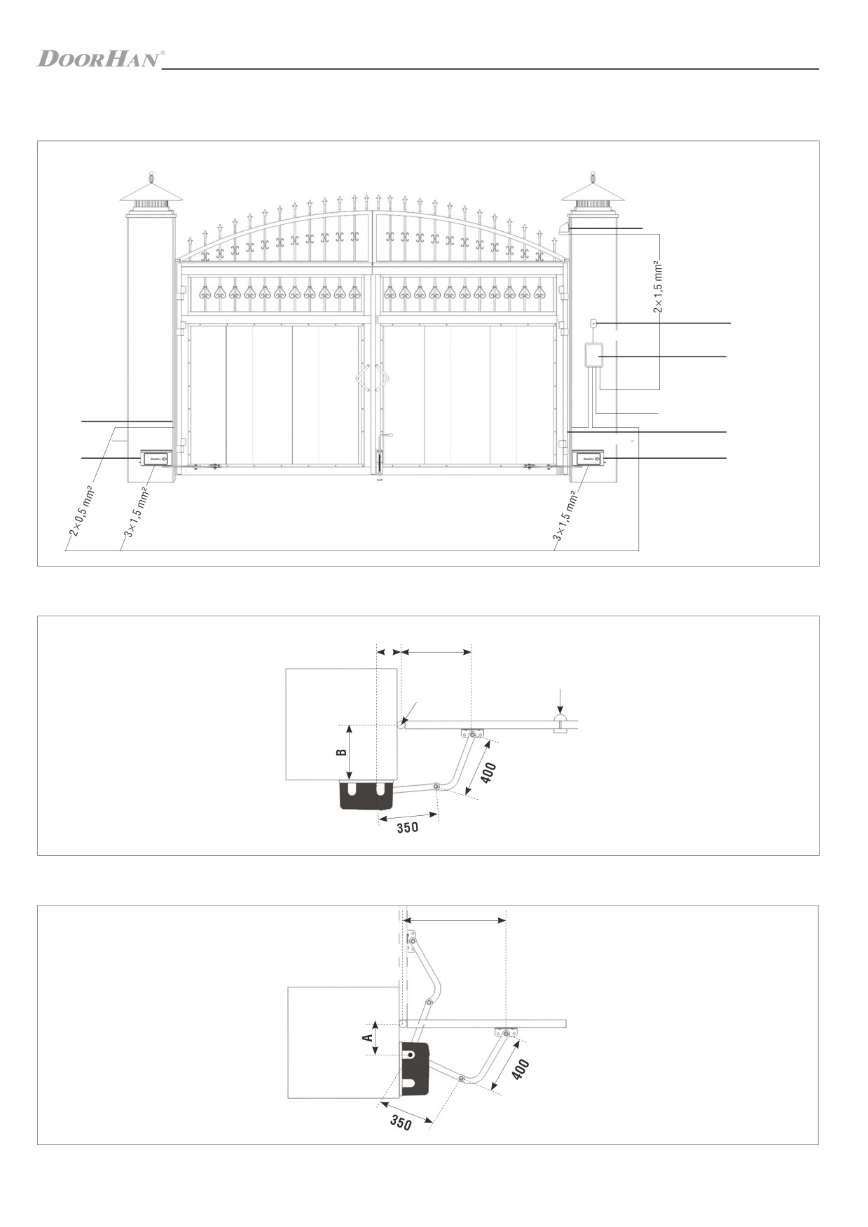
СХЕМА ПРОКЛАДКИ КАБЕЛЯ / CABLE LAYING SCHEME
1.
Привод / Operator
2.
Фотоэлементы /
Photocells
3.
Блок управления /
Control block
5
4.
Ключ-кнопка / Key
Button
5.
Сигнальная лампа /
Signal lamp
4
2 × 0,5 mm2
3
3 × 1,5 mm2
2
(220-240 V)
2
4 × 0,5 mm2
1
1
ОТКРЫТИЕ ВНУТРЬ / OPENING INSIDE
A
450
механический
упор / stopper
колонна / column
петля / hinge
Если 0 < В ≤ 300 (мм), то А ≥ 110 (мм)/
If 0 < B ≤ 300 (mm), then A ≥ 110 (mm).
Если 300 < В ≤ 380 (мм), то А ≥ 150 (мм)/
If 300 <B ≤ 380 (mm), then A ≥ 150 (mm).
ОТКРЫТИЕ НАРУЖУ / OPENING OUTSIDE
450
100 ≤ А ≥ 300 (мм) / 100 ≤ A ≥ 300 (mm).
3

ARM-320PRO
ВАРИАНТЫ УСТАНОВКИ ПРИВОДА / INSTALLATION OPTIONS
МОНТАЖ НА КОЛОНУ ОТКРЫТИЕ ВНУТРЬ / INSTALLATION ON COLUMN, OPENING INSIDE
МОНТАЖ НА СТВОРКУ ОТКРЫТИЕ ВНУТРЬ / INSTALLATION ON GATE PANEL, OPENING INSIDE
МОНТАЖ НА КОЛОНУ ОТКРЫТИЕ НАРУЖУ / INSTALLATION ON COLUMN, OPENING OUTSIDE
4

ARM-320PRO
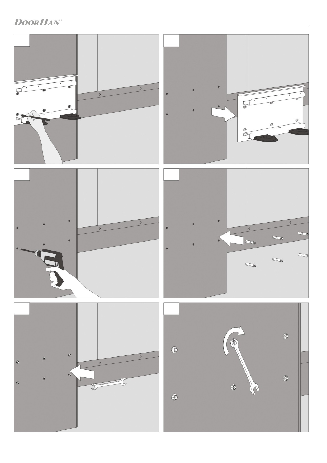
МОНТАЖ / INSTALLATION
1
2
3
4
5
6
5

ARM-320PRO
7
8
9
10
11
12
6
ARM-320PRO
13
14
15
16
17
18
7

ARM-320PRO
19
20
21
22
23
24
8

ARM-320PRO
25
26
27
28
29
30
9

ARM-320PRO
31
32
33
34
35
36
10

ARM-320PRO
НАСТРОЙКА КОНЦЕВЫХ ПОЛОЖЕНИЙ / SETTING UP END POSITIONS
1
2
3
4
5
6
11

ARM-320PRO
7
8
9
10
11
12
12

ARM-320PRO
ПОДКЛЮЧЕНИЕ ПИТАНИЯ МОТОРА / MOTOR POWER CONNECTION
1
2
3
4
5
6
13

ARM-320PRO
7
УСТАНОВКА ПРАВОСТОРОННЕГО ПРИВОДА/ INSTALLATION OF RIGHT-HAND OPERATOR
1
2
3
4
14

ARM-320PRO
5
6
7
8
9
10
15

ARM-320PRO
11
12
13
14
15
16
16
содержание .. 1 2 3 4 ..