Hyundai Excavator R210LC-7. Service and repair manual - page 34


  Index      Manuals     Hyundai Excavator R210LC-7. Service and repair manual


Search            copyright infringement  


Content      ..     32      33      34      35     ..


Hyundai Excavator R210LC-7. Service and repair manual - page 34


8-101

B : ADJUSTING BALL BEARINGS

Ball bearings(22) must be given a correct
pressure to serve its full life.   If a part that
affects the bearing pressure is replaced,
therefore, readjust the bearing pressure
according to the following procedure.
Take notice when motor is reassembled
ensure that all adjustments are absolutely
correct.   Failure to have correct
adjustments will result in damage to the
motor early in use.
Parts that affect the bearing pressure
include: Hub(1), spindle assembly and ball
bearings(21).
Confirm and readjust the ball bearings
pressure as follows:

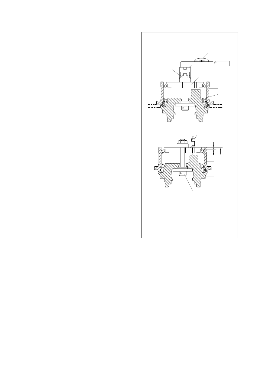
Attach the ball bearings pressure
adjustment jig to spindle(2).   Press fit ball
bearings(21) into the hub(1) by tightening
the special nut with a torque of 12 2kgf m
(86.8 11.5lbf ft)

Insert a depth micrometer through the
measuring hole in ball bearings pressure
adjustment jig and determine the depth as

A

.

Because the 

B

dimension of ball bearing

pressure adjustment jig is known,
clearance 

C

can be determined as follows:

C  =  A  -  B

(1)

(2)

(3)

B

Depth micro meter

A

Hub

Spindle

C

Adjust jig

Adjust jig

Hub
Spindle

Special nut

Torque lench

A

Measured value

B

Jig dimension

C

Required clearance

25038TM18(1)

8-102

Measure dimension 

D

of hold flange(3).

Based on the results obtained from step
(2) through(4), adjust hold flange(3) as
follows.(Dimension 

C

is the required

clearance of hold flange):

If measured dimension 

D

of hold flange

(3) is smaller than the required value:
Grind down surface 

E

of hold flange(3)

with a lathe or other machine so that
dimension 

D

equals the required value.

If measured dimension 

D

of hold flange

(3) is within the tolerance of the required
value: 
Use hold flange(3) as it is.
If measured dimension 

D

of hold flange

(3) is greater than the required value:
Use a new spindle assembly.
Dimension 

D

of a new hold flange(3)

allows for adjustment.

Remove the ball bearings pressure
adjustment jig from spindle(2).

(4)

(5)

(6)

The surface(E)

Hold flange

D

25038TM18(2)

8-103

If any of the following parts has been
replaced, readjust the axial clearance of
the taper roller bearings(22) selecting
distance pieces(13) having a suitable
thickness:
Hub(1), spindle assembly, RV gear
assembly and snap rings(20).
Take notice when motor is reassembled
ensure that all adjustments are absolutely
correct.
Failure to have correct adjustments will
result in damage to the motor early in use.
If none of the above parts has been
replaced, on axial clearance adjustment is
required.
Adjust the axial clearance of the taper
roller bearings as follows:

RV gear assembly

Taper roller bearing

Retainer

C : ADJUSTING AXIAL CLEARANCE OF TAPER ROLLER BEARINGS

Apply the retainer to the outer races of
taper roller bearings(22) on the
crankshafts(9) and lightly hammer it.
Hammering makes insertion of the RV
gear assembly into the spindle(2) easier.

Install the least thick distance pieces(13)
in the hold flange(3).

Move the retainer to another point on
distance pieces(13) each after lightly
hammering it.
Confirm that the RV gear assembly is
secured to the spindle(2) in place.

Install the snap rings(20) in the snap ring
grooves in the hold flange(3).

Measure the clearance between the snap
rings(20) and the taper roller bearings(22)
with a thickness gauge.

(1)

(2)

(3)

(4)

(5)

25038TM19

8-104

Determine whether the thickness of the
snap rings(20) is suitable.

(6)

Select another distance pieces from 17
available types, install it in between
distance pieces(13) and snap rings(20).

(7)

Max =

+

Thickness gauge
thickness

Distance piece
thickness

Min =

+

- 0.05

Thickness gauge
thickness

Distance piece
thickness

8-105

ASSEMBLY PROCEDURE

Assembling the brake valve section
and hydraulic motor section

Fit friction plate(115) and then mating
plate(116), one by one, into the grooves
of the outer surface of cylinder block(104).
Immerse the friction plate in a hydraulic
oil before fitting them.
Do not make a mistake order, friction
plate(115) and mating plage(116).
Because it make braking torque down.

4)

(1)

Mount O-rings(135, 139) in the O-ring
grooves of piston(112) after applying
grease them.
Mount piston(112) in spindle(2).
If the piston(112) do not fit into the
spindle(2) because of the resistance of
the O-ring tap the edge of the piston(112)
lightly and equally with a plastic hammer.
Be careful not to damage the O-ring at
this time.

Ball bearing(150), parallel pin(341),
timing plate(109), twelve springs(113) into
the rear flange(101).
Apply hydraulic oil to ball bearing(150).
Apply grease timing plate(109) and
twelve springs(113).   Because the coat
of grease will keep the two faces.

Hydraulic oil flow into spindle(2).   Fit O-
rings(27, 29) in the grooves provided in
the mating face of spindle(2) without
grease.   Two parallel pins(42) into
spindle(2).   And install rear flange(301)
onto spindle(2) so that the two parallel
pins(42) on the spindle enter the dowel
holes in the rear flange.

Quantity required : Hydraulic oil 1.7 liters

25038TM08(1)

25038TM07(4)

25038TM03(1)

25038TM02(4)

8-106

Tighten the twelve hexagon socket bolts
(343) to the specified torque.

Tightening torque : 25.7 4kgf m

(185.9 28.9lbf ft)

The O-ring(355) insert a plug(357) and
tighten it to the specified torque.(For not
using drain port.)

Tightening torque : 10 2kgf m

(72.3 14.5lbf ft)

Install relief valves to rear flange(301).
Tighten relief valves to the specified
torque.

Tightening torque : 25 5kgf m

(180.8 36.2lbf ft)

Assembling the reduction gear /
Hydraulic motor shafts and oil seal

Install coupling(15) to motor shaft.
Install input gear(6) to coupling(15).   And
steel ball(36) put into the hole of input
gear(6).
Apply grease to steel ball(26).
Fit O-ring(30) in the O-ring groove of
cover(8).
Apply grease to O-ring(30).
Lift and install cover(8) to hub(1) by using
eye bolts, plastic hammer and lifting tool.
Need careful handling for not damaging
O-ring(30).

(2)

25038TM02(3)

25038TM02(2)

25038TM09(4)

25038TM03(3)

8-107

Tighten the twelve hexagon socket bolts
(35) to the specified torque.
Gear oil flow into the hub(1).

Tightening torque : 10.4 1.6kgf m

(75.2 11.6lbf ft)

Quantity required : Gear oil 5.4 liters

The O-ring(43) insert hexagon socket
plugs(33) and tighten it to the specified
torque.(For three gear oil ports.)

Tightening torque : 10 2kgf m

(72.3 14.5lbf ft)

This completes assembly.

25038TM03(2)

25038TM03(3)

25038TM02(1)

8-107-1

B. TRAVEL DEVICE(SBTR220, #2079 and up)

1.  REMOVAL AND INSTALL 

REMOVAL

Swing the work equipment 90

and lower it

completely to the ground.

Operate the control levers and pedals
several times to release the remaining
pressure in the hydraulic piping.

Loosen the breather slowly to release the
pressure inside the hydraulic tank.
Escaping fluid under pressure can
penetrate the skin causing serious injury.
When pipes and hoses are disconnected,
the oil inside the piping will flow out, so
catch it in oil pan.

Remove the track shoe assembly.
For details, see r

r

emoval  of  track  shoe

assembly.

Remove the cover.

Remove the hose.
Fit blind plugs to the disconnected hoses.

Remove the bolts and the sprocket.

Sling travel device assembly(1).

Remove the mounting bolts(2), then
remove the travel device assembly.

·

Weight : 300kg(660lb)

INSTALL

Carry out installation in the reverse order
to removal.

Bleed the air from the travel motor.

Remove the air vent plug.
Pour in hydraulic oil until it overflows from
the port.
Tighten plug lightly.
Start the engine, run at low idling, and
check oil come out from plug.
Tighten plug fully.

Confirm the hydraulic oil level and check
the hydraulic oil leak or not.

B

Dr

A

P

2

1

1)

2)

(1)

(2)

(3)

(4)

(5)

(6)

(7)

(8)

(9)

(1)

(2)


(3)

13031GE18

21078DA47

8-107-3

TOOLS AND TIGHTENING TORQUE

Tools

(1)

2)

Tool name

Remark

Allen wrench

Socket for socket wrench, spanner

Torque wrench

Pliers

Plastic and iron hammer

Monkey wrench

Oil seal inserting jig

Bearing pliers

Seal tape

Eye bolt

Press(0.5 ton)

Oil stone

Bearing assembling jig

2.5, 4, 6, 10 

8, 14, 24, 27

Socket

Capable of tightening with the specified torques

-

Wooden hammer allowed. Normal 1 or so

-

-

-

-

M10, M12, M14

-

-

-

Part name

Item

Size

Torque

kgf

·

m

lbf

·

ft

Plug

Orifice

Wrench bolt

Relief valve

Plug

Plug

Plug

Wrench bolt

Hex head bolt

Hex socket head bolt

Hex socket head plug

2

26

45

46

54

58

62

71

-

-

-

NPTF 1/16

M5

M12

×

40L

HEX 27

PF 1/2

HEX 24

PF 1/4

M10

×

35L

M12

×

25L

M12

×

155L

PF 3/4

1

±

0.1

0.7

±

0.1

10

±

1.0

18

±

1.0

8.5

±

1.0

5

±

1.0

5

±

1.0

10

±

1.0

11

±

1.5   

11

±

1.5   

19

±

1

7.2

±

0.7

5

±

0.7

72

±

7.0

130

±

7.0

61

±

7.0

36

±

7.0

36

±

7.0

72

±

7.0

79

±

10

79

±

10

137

±

7.0

T

T

ightening torque

(2)

B

8-107-4

3.  OUTLINE OF DISASSEMBLING 

GENERAL SUGGESTIONS

Select a clean place for dismantling.
Spread a rubber plate on a working table in order to prohibit the damage of parts.

Clean a deceleration equipment and a motor part, washing out dirt and unnecessary substances.

Without any damage of O-ring, oil seal, the adhered surface of other seals, a gear, a pin, the
adhered surface of other bearings, and the surface of moisturized copper, treat each parts.

Numbers written in the parenthesis, ( ), next to the name of a part represent the part numbers of a
cross-sectional view annexed with a drawing.

The side of a pipe in a motor can be written as a rear side; the side of out-put as a front side.

Using and combining a liquid gasket, both sides must be dried completely before spraying a liquid
gasket.

In case of bonding volts, combine a standard torque by torque wrench after spraying rocktight 262
on the tab parts.  (It can be dealt as assembling NPTF screws and an acceleration equipment.)

1)

(1)

(2)

(3)

(4)

(5)

(6)

(7)

3.1  DISASSEMBLING 

Unloosing wrench bolt and disassemble
cover(37).
Wrench bolt = M12

×

40L-8EA 

(Purchasing goods)

1)

21078TM21

Disassemble parts related to C.B.V.

2)

21078TM22

8-107-5

Unloosing wrench bolt(M12

×

35L, 16EA)

and disassemble rear cover assembly from
motor assembly.

3)

21078TM23

21078TM24

Dismantle packing piston(21) using
compressed air.

4)

21078TM25

Disassembly rotary kit from motor
assembly(Cylinder block assembly, piston
assembly, ball guide, set plate, friction plate,
steel plate...)

5)

21078TM26

8-107-6

Using a jig, disassemble swash plate(9)
from shaft casing.

6)

21078TM27

Using compressed air, disassemble piston
swash(4) piston ring(5), respectively.

7)

21078TM28

21078TM29

Using a hammer, disassemble shaft(6) from
shaft casing(1).

8)

21078TM30

8-107-7

Disassemble cylinder sub.

Disassemble cylinder block assembly,
piston assembly(9) and seat plate(M). 

9)

21078TM31

21078TM32

Disassemble ball guide(16), ring and
pin(15) from cylinder block, respectively.

10)

21078TM33

21078TM34

8-107-8

21078TM35

Pushing spring(12) by an assembling jig,
disassemble snap ring(14), spring seat(13),
spring(12) and spring seat(11), respectively.

11)

21078TM36

21078TM37

Disassemble valve casing sub.

Using an hexagon wrench, unloosing
wrench bolt(45) and disassemble cover(37),
spring(38), spool(39), spring seat(43),
spring(36) and spring seat(35), respectively.
(Same balance on both sides)

12)

21078TM38

8-107-9

21078TM39

Disassemble spool(59), spool(47), O-ring
(51), guide(48) and snap ring(53) on rear
cover, respectively.

13)

21078TM40

21078TM41

Using a torque wrench, disassemble relief
assembly(46) on rear cover.

14)

21078TM42


Content      ..     32      33      34      35     ..