Hyundai Excavator R210LC-7. Service and repair manual - page 35


  Index      Manuals     Hyundai Excavator R210LC-7. Service and repair manual


Search            copyright infringement  


Content      ..     33      34      35      36     ..


Hyundai Excavator R210LC-7. Service and repair manual - page 35


8-107-10

4.  OUTLINE FOR ASSEMBLING 

GENERAL SUGGESTIONS

After washing each parts cleanly, dry it with compressed air.
Provided that you do not wash friction plate with treated oil.

In bonding each part, fasten bond torque.

When using a hammer, do not forget to use a plastic hammer.

1)

(1)

(2)

(3)

4.1  ASSEMBLING 

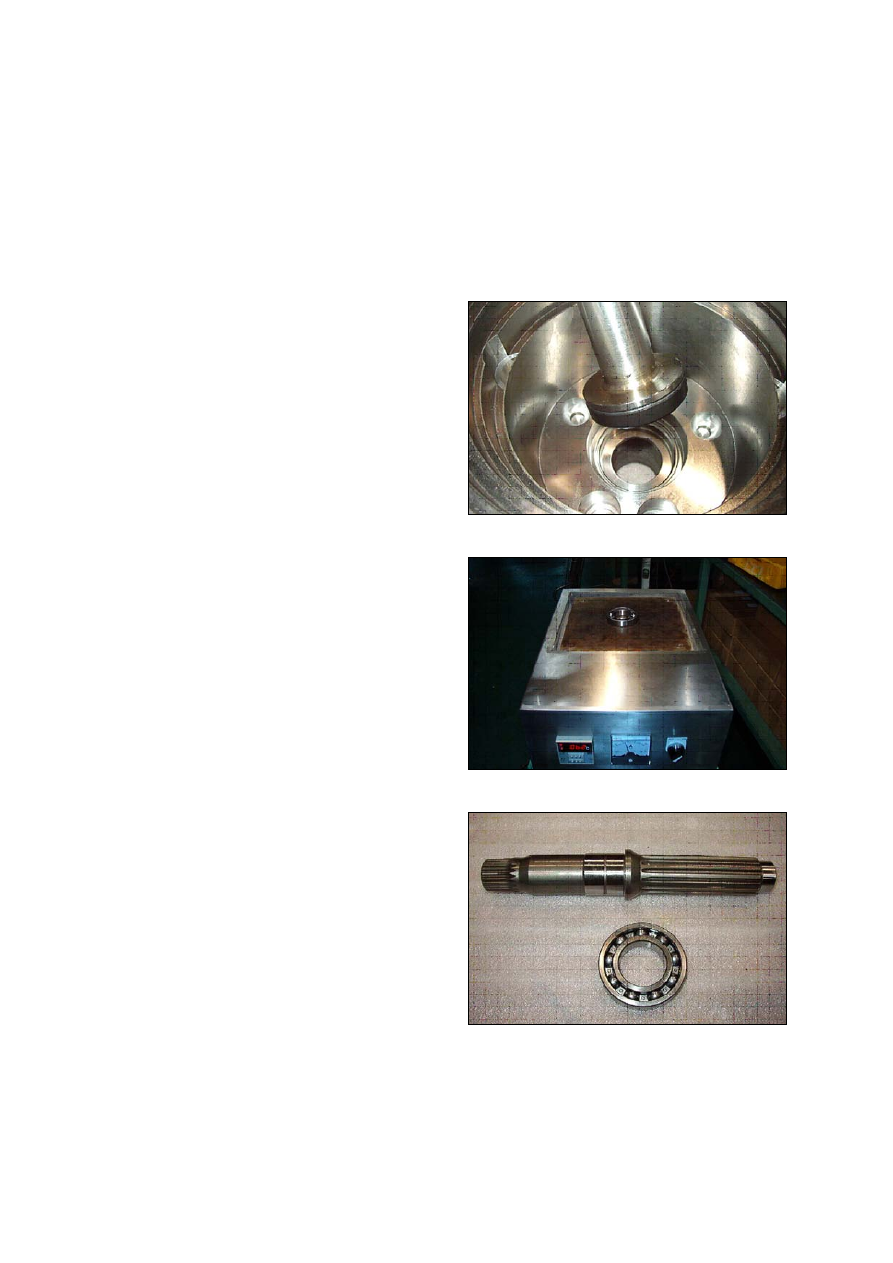
Assemble the sub of turning axis

Using a jig, assemble oil seal(3) into shaft
casing(1)

1)

21078TM43

Have a bearing(8) thermal reacted into
shaft(6).

2)

21078TM44

21078TM45

8-107-11

21078TM46

Using a jig, assemble shaft assembly into
shaft casing(1).

3)

21078TM47

After spreading grease on steel ball(8)
assemble into shaft casing(1).

4)

21078TM48

Assemble swash piston assembly(4, 5) into
shaft casing(1).

5)

21078TM49

8-107-12

Assemble swash plate(9) into shaft casing
(1).

6)

21078TM50

Assemble cylinder block sub.

Assemble spring seat(13), spring(12),
spring seat(11) into cylinder block(10)
respectively, pushing spring(12) using by a
jig, assemble snap ring(14) with a snap
ring(14).

7)

21078TM51

21078TM52

8-107-13

Assemble ring, pin(15) on cylinder block(10)
ball guide(16) respectively.

8)

21078TM53

21078TM54

21078TM55

Assemble cylinder block assembly, piston
assembly(9), seat plate(17).

9)

21078TM56

8-107-14

21078TM57

Assemble cylinder block assembly(9) into
shaft casing(a).

10)

21078TM58

Assemble friction plate(19) and plate(20)
into shaft casing(1) respectively, prepare 6
set.

11)

21078TM59

21078TM59-1

8-107-15

Assemble O-ring(22, 23) into packing piston
(21).

12)

21078TM60

21078TM60-1

After spreading grease on packing
piston(21) bond wrench bolt and assemble
shaft casing(1).

13)

21078TM61

Assemble rear cover sub.

Using a jig, assemble bearing(69) into rear
cover(29).

14)

21078TM62

8-107-16

After assembling spool(59), spool(47),
O-ring(51), guide(48) and snap ring(53)
respectively into rear cover(29).
Using torque wrench, assemble it.

15)

21078TM63

21078TM64

21078TM65

8-107-17

Assemble spring seat(35), spring(36),
spring seat(43), spool(39), spring(38),
cover(37) respectively and assemble
wrench bolt(45).
(Same balance on both sides)

16)

21078TM66

21078TM67

21078TM67-1

8-107-18

Assemble plug(2).

Plug(NPT1/16) - 11EA

17)

21078TM68

21078TM69

21078TM70

21078TM71

8-107-19

Assemble plug(64).

Plug(PT3/8) - 11EA

18)

21078TM72

Assemble plug(62, 63) into rear cover(29)
and assemble relief valve assembly.

19)

21078TM73

21078TM74

Put spring(67, 68) together into rear cover
(29), prepare 6 set.

20)

21078TM75

8-107-20

21078TM76

Assemble valve plate(70) into rear cover
(29).

21)

21078TM77

After assembling shaft casing(1) and rear
cover(29).
Assemble spool assembly(30), spring(38),
spool(39), cover(37) after then complete
assembly with wrench bolt(45).

22)

21078TM78

Finish assembly.

23)

21078TM79

Setting reduction unit(or whole propelling
unit) on work stand for disassembling

Remove M12 hexagon socket head
bolts(95) at 3 places from cover(93)
almost equally apart each other, and then
install M12

×

155L eye bolts.

Lift up the unit using them and place it on
work stand with cover upward.

T

T

ake great care not to pinch your hand

between  parts  while  disassembling  nor
let  fall  parts  on  your  foot  while  lifting
them.

(1)

8-107-21

5.1  DISASSEMBLING REDUCTION UNIT 

Preparation for disassembling

The reduction units removed from excavator are usually covered with mud.  Wash outside of
propelling unit and dry it.

Locate reducer in order for drain port to be at the lowest level loosen taper screw plug of drain
port, and drain oil from reduction gear.
While oil is still hot, inside of the unit may be pressurized.

Take care of the hot oil gushing out of the unit when loosening the plug.

1)

(1)

(2)

Mark for mating
Put marks on each mating parts when
disassembling so as to reassemble
correctly as before.

(3)

21078TM80

2)

21078TM81

Removing cover

Remove the rest of M12 hexagon socket
head bolts(95) that securering gear and
housing.  Loosen all the socket bolts and
then, disassemble cover.

As the cover(93) is adhered to ring gear
(88), disassemble ring gear(88) and cover
(93) vy lightly hammering slantwise
upward using sharpen punch inserted
between the cover and ring gear.

3)

21078TM82

(1)

(2)

8-107-22

Removing No.1 carrier sub assembly

Screw three M10 eye-bolt in No.1 carrier
and lift up and remove No.1 carrier assy.

4)

21078TM83

(1)

Remove No.1 sun gear

Be sure to maintain it vertical with the
ground when disassembling No.1 sun
gear.

21078TM84

(2)

Removing No.2 carrier sub assembly

Screw three M10 eye-bolt in No.2 carrier
and lift up and remove No.2 carrier assy.

5)

21078TM85

(1)

Remove No.2 sun gear

Be sure to maintain it vertical with the
ground when disassembling No.2 sun
gear.

21078TM86

(2)

8-107-23

Removing ring gear

As the ring gear(88) is adhered to
housing(81), disassemble ring gear(88)
and housing(81) by lightly hammering
slantwise upward using sharpen punch
inserted between the ring gear and
housing.
Carefully disassembling ring gear not to
make scratch on it.

Screw M14 eye-bolt in ring gear and lift up
and remove it.

6)

21078TM87

(1)

(2)

Removing coupling

Remove coupling.

7)

21078TM88

(1)

Removing retainer & shim

Remove M12 hexagon socket head  bolts
that secure retainer and motor.

Remove retainer & shim.

8)

21078TM89

(1)

(2)

Removing housing sub assembly

Screw M12 eye bolt in housing and lift up
housing assembly including anguler
bearing and floating seal.

9)

21078TM90

(1)

8-107-24

Removing floating seal

Lift up a piece of floating seal of motor
side.

10)

21078TM91

(1)

Disassembling housing assembly

After turning housing, lift up a piece of
floating seal from housing and then
remove it.
Don't disassemble anguler bearing.

11)

21078TM92

(1)

Disassembling No.1 carrier

Remove thrust ring(90-7) from carrier.

Knock spring pin(91-8) fully into No.1 pin
(91-7).

Remove planetary, thrust washer, No.1
pin, bearing from carrier.

12)

21078TM93

21078TM94

(1)

(2)

(3)

8-107-25

21078TM95

Disassembling No.2 carrier

Disassemble No.2 carriers, using the
same method for No.1 carrier assembly.

13)

21078TM96

21078TM97

(1)


Content      ..     33      34      35      36     ..