Hyundai Excavator R210LC-7. Service and repair manual - page 33
8-85
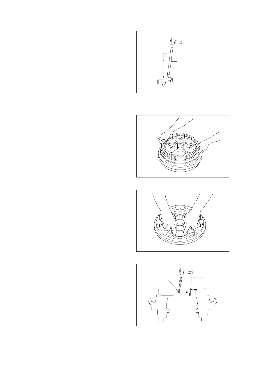
Hammer
Sharpen punch
Ball bearing
Disassembly of ball bearing(21)
Remove the floating seal(31) from hub(1).
Turn the motor upside down.
Remove the ball bearing(21) from hub(1)
by applying a sharpen punch to ball
bearing(21) and hammering the punch.
When ball bearing(21) comes off from
hub(1), the ball bearing will drop. To
prevent damage due to the dropping,
place a receptacle covered with a rubber
under the work bench.
(7)
Disassembly spindle fittings
Remove the floating seal(31) from hub(1).
Remove the outer ring of tapered roller
bearing(22) from spindle(2).
(8)
Disassembly the outer ring of tapered
roller bearing(22) from hold flange(3)
Remove three outer rings of tapered roller
bearings(22) from hold flange(3).
(9)
Oil seal
Disassembly of oil seal(132)
Remove oil seal(132) from spindle(2) as
shown below.
Do not reuse removed oil seal(132).
(10)
25038TM17(1)
25038TM11(1)
25038TM11(2)
25038TM17(2)