Index Manuals Hyundai Excavator R210LC-7. Service and repair manual
Search copyright infringement
Content .. 30 31 32 33 ..
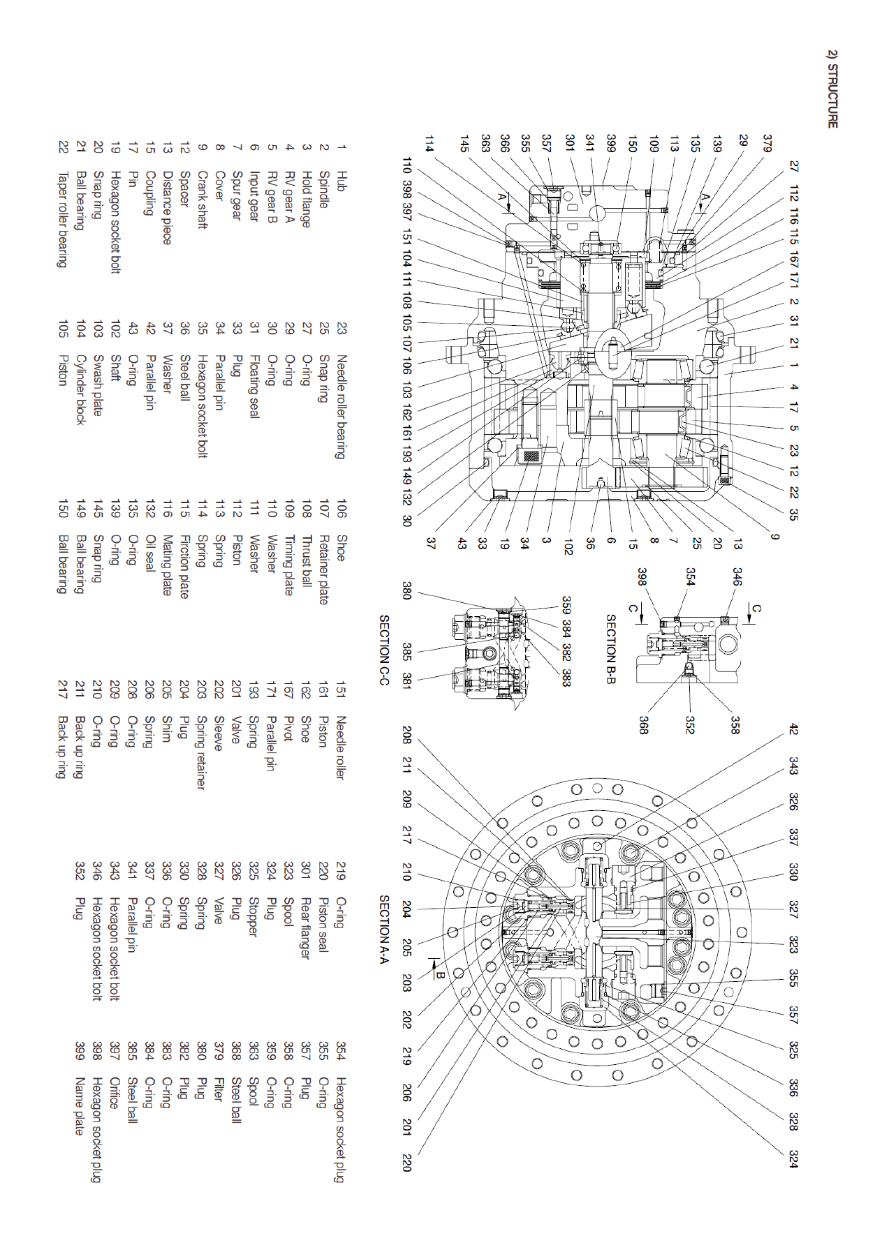
Hyundai Excavator R210LC-7. Service and repair manual - page 32