Index Manuals Aprilia RS 250. Repair Manual
Search
Content .. 16 17 18 19 ..
Aprilia RS 250. Manual - part 18
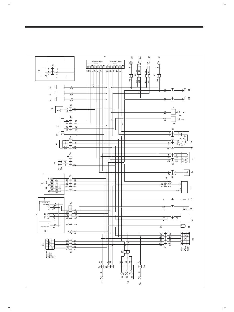
SCHEMA ELETTRICO -
WIRING DIAGRAM - ESQUEMA ELECTRICO
6 - 41
M
IMPIANTO ELETTRICO
Mod.1996