Aprilia RS 250. Manual - part 17
ELECTRICAL SYSTEM
6 - 26
INSTALACION ELECTRICA
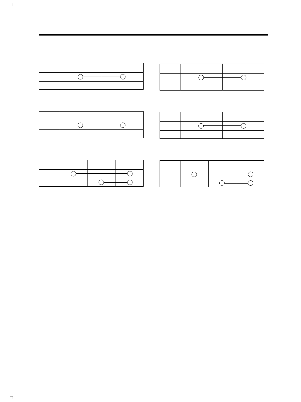
NEUTRAL SWITCH
B
–
ON
OFF
SIDE STAND SWITCH
M
V
N
ON
OFF
REAR STOP SWITCH
G
G
ON
OFF
BATTERY
Type : 12 V - 4 Ah
ACTIVATION AND MAINTENANCE
●
Remove the battery from the motorcycle.
●
Remove the plugs from the elements and the
breather plug.
●
Fill the cells with electrolyte fluid with a speci-
fic weight of 1,3.
●
Charge the battery slowly (with an amperage
of 1/10 its capacity) for at least 10 hours and
reassemble it on the motorcycle at the moment
of delivery to the customer (when a distance of
some kilometres is expected to be covered).
●
Reassemble the battery on the motorcycle, and
connect the battery terminals and the breather
hose.
●
If the motorcycle stands idle for a considerable
amount of time, it is necessary to recharge the
battery periodically (at least once a month) for
at least 10 hours (eg during prolonged winter
stoppages).
●
Top up the level of the electrolyte periodically
(once a month) only with distilled water.
INTERRUPTOR DEL PUNTO MUERTO
B
–
ON
OFF
INTERRUPTOR DEL CABALLETE LATERAL
M
V
N
ON
OFF
INTERRUPTOR DE STOP TRASERO
G
G
ON
OFF
BATERIA
TIPO : 12 V - 4 Ah
FUNCIONAMIENTO Y MANTENIMIENTO
●
Desmontar la batería de la motocicleta.
●
Sacar los tapones de los elementos y el tapón
de desfogue.
●
Llenar las células de líquido electrólito con pe-
so específico 1,3.
●
Poner la batería a una carga lenta (con ampe-
raje igual a 1/10 de la capacidad de la batería)
por unas 10 horas como mínimo y volverla a
montar en la motocicleta en el momento de la
entrega al cliente, es decir, cuando se cree que
se realizará un recorrido kilométrico.
●
Instalar la batería en la motocicleta, conectar
los terminales y el tubo de desfogue.
●
En caso de una parada muy larga de la motoci-
cleta, es necesario recargar periódicamente
(una vez al mes como mínimo) la batería por
unas 10 horas (caso típico la parada invernal
muy larga).
●
Restablecer periódicamente (una vez al mes) el
nivel del líquido electrolítico solamente con
agua destilada.