Range Rover. Manual - part 322


  Index      Land Rover     Range Rover P38 - service manual 1995 year


Search            


Content   ..  320  321  322  323   ..


Range Rover. Manual - part 322


ELECTRICAL

29

REPAIR

FASCIA MOUNTED SWITCHES

Remove

1. Remove instrument pack binnacle.

See

INSTRUMENTS, Repair.

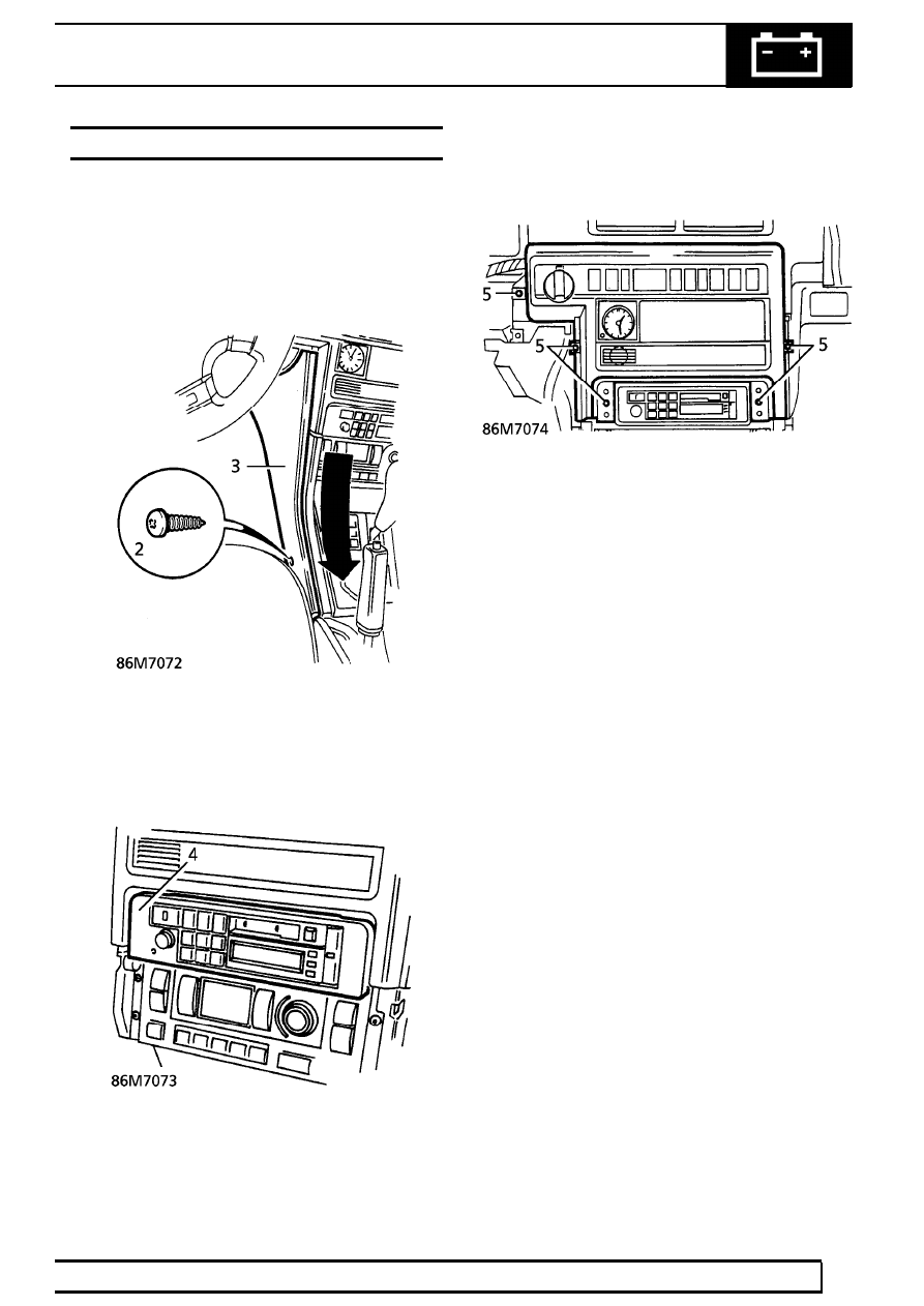
2. Remove screw securing each side panel to

centre console.

3. Disengage sprag clips from fascia switch pack.

Remove side panels.

4. Remove radio applique.

5. Remove 5 screws securing switch pack.

86

ELECTRICAL

NEW RANGE ROVER

30

REPAIR

6. Release switch pack from fascia.

7. Disconnect multiplug from relevant switch.
8. Release clips securing switch to switch pack.

Remove switch.

Refit

9. Reverse removal procedure.

HARNESS - FRONT DOOR

Service repair no - 86.70.65

Remove

1. Remove plastic sheet.

See CHASSIS AND

BODY, Repair.

2. Disconnect window lift motor multiplug.

3. Disconnect puddle lamp multiplug.
4. Disconnect door mirror multiplug.
5. Disconnect 2 door latch motor multiplugs.
6. Release door to body harness sheath at both

ends.

7. Release 2 door harness connectors from body

and disconnect.

8. Release 8 clips securing door harness.
9. Remove harness from door.

Refit

10. Reverse removal procedure.

ELECTRICAL

31

REPAIR

FRONT FOG LAMP

Service repair no - 86.40.96

Remove

1. Raise the vehicle.

WARNING: Support on safety stands.

2. Disconnect multiplug.

3. Disconnect 2 breather tubes.

4. Remove 4 screws securing fog lamp to bumper.
5. Remove fog lamp assembly.

Refit

6. Reverse removal procedure.

FRONT SPEAKER

Service repair no - 86.50.15

Remove

1. Remove front door trim casing.

See CHASSIS

AND BODY, Repair.

2. Remove 4 screws securing speaker.

3. Release speaker. Disconnect multiplug. Remove

speaker.

Refit

4. Reverse removal procedure.

86

ELECTRICAL

NEW RANGE ROVER

32

REPAIR

TWEETER SPEAKER - FRONT DOOR

Service repair no - 86.50.34

Remove

1. Remove cheater panel from door.
2. Rotate tweeter speaker to release from cheater.

3. Disconnect terminals. Remove speaker.

Refit

4. Reverse removal procedure.

IGNITION SWITCH

Service repair no - 86.65.02

Remove

1. Disconnect battery negative lead.
2. Remove steering column nacelle.

See

STEERING, Repair.

3. Remove 3 bolts securing steering tilt lever to

column.

4. Release column tilt lever assembly and plunger.
5. Collect lever return spring.
6. Collect plunger and spring if necessary.
7. Remove 2 screws securing ignition switch.


Content   ..  320  321  322  323   ..