Jeep Grand Cherokee WK. Manual - part 1270


  Index      Jeep     Jeep Grand Cherokee WK - service repair manual 2005 year


Search            


Content   ..  1268  1269  1270  1271   ..


Jeep Grand Cherokee WK. Manual - part 1270


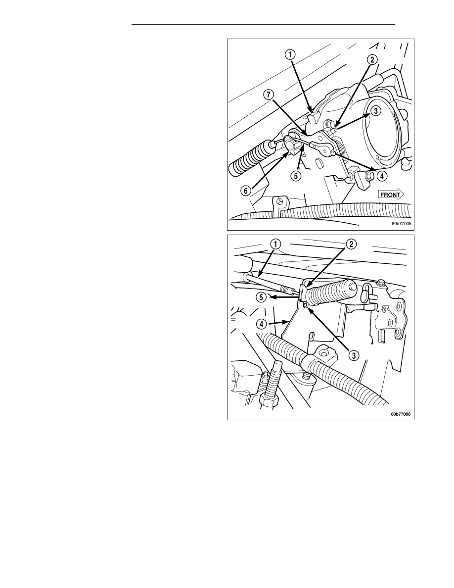
7. Using finger pressure only, disconnect accelerator

cable connector at throttle body bellcrank pin by
pushing connector off bellcrank pin towards front of
vehicle (4). DO NOT try to pull connector off
perpendicular to bellcrank pin. Connector will
be broken.

8. Lift accelerator cable from top of cable cam (6).

9. Press tab (3) to release plastic cable mount from

bracket. Press on tab only enough to release
cable from bracket. If tab is pressed too much,
it will be broken. 
Slide plastic mount (2) towards
passenger side of vehicle to remove cable from
bracket.

10. Remove throttle cable from vehicle.

14 - 54

FUEL INJECTION

WK

INSTALLATION

3.7L V-6

1. Slide accelerator cable plastic mount into throttle

body

mounting

bracket.

Continue

sliding

until

release tab (2) is aligned to hole in mounting
bracket.

2. Hold throttle in wide open position. While held in

this position, slide throttle cable pin (1) into throttle
body bellcrank.

WK

FUEL INJECTION

14 - 55

3. Push rubber grommet (3) through opening in dash panel.

4. From inside vehicle, slide throttle cable core wire into opening (slot) in top of pedal arm.

5. Push plastic cable retainer (clip) (2) into pedal arm opening until it snaps in place.

6. Install air resonator tube to throttle body.

7. Before starting engine, operate accelerator pedal to check for any binding.

4.7L V-8

1. Slide accelerator cable plastic mount into bracket.

Continue sliding until tab (3) is aligned to hole in
mounting bracket.

2. Route accelerator cable over top of cable cam.

3. Connect cable end to throttle body bellcrank pin

(snaps on rearward).

4. Slide rubber grommet away from plastic cable

housing.

14 - 56

FUEL INJECTION

WK

5. Install rubber grommet (3) into dash panel until seated.

6. Push cable housing into rubber grommet and through opening in dash panel.

7. From inside vehicle, slide throttle cable core wire into opening (6) in top of pedal arm.

8. Push cable retainer (clip) (2) into pedal arm opening until it snaps in place.

9. Snap cable into dashpanel routing clip.

10. Install air resonator tube to throttle body.

11. Before starting engine, operate accelerator pedal to check for any binding.

SENSOR-THROTTLE POSITION

DESCRIPTION

The 3-wire Throttle Position Sensor (TPS) is mounted on the throttle body and is connected to the throttle blade
shaft.

The 5.7L V-8 engine does not use a separate TPS on the throttle body.

OPERATION

The 5.7L V-8 engine does not use a separate Throttle Position Sensor (TPS) on the throttle body.

The 3–wire TPS provides the Powertrain Control Module (PCM) with an input signal (voltage) that represents the
throttle blade position of the throttle body. The sensor is connected to the throttle blade shaft. As the position of the
throttle blade changes, the output voltage of the TPS changes.

The PCM supplies approximately 5 volts to the TPS. The TPS output voltage (input signal to the PCM) represents
the throttle blade position. The PCM receives an input signal voltage from the TPS. This will vary in an approximate
range of from .26 volts at minimum throttle opening (idle), to 4.49 volts at wide open throttle. Along with inputs from
other sensors, the PCM uses the TPS input to determine current engine operating conditions. In response to engine
operating conditions, the PCM will adjust fuel injector pulse width and ignition timing.

The PCM needs to identify the actions and position of the throttle blade at all times. This information is needed to
assist in performing the following calculations:

Ignition timing advance

Fuel injection pulse-width

Idle (learned value or minimum TPS)

Off-idle (0.06 volt)

WK

FUEL INJECTION

14 - 57


Content   ..  1268  1269  1270  1271   ..