Jeep Grand Cherokee WK. Manual - part 1268


  Index      Jeep     Jeep Grand Cherokee WK - service repair manual 2005 year


Search            


Content   ..  1266  1267  1268  1269   ..


Jeep Grand Cherokee WK. Manual - part 1268


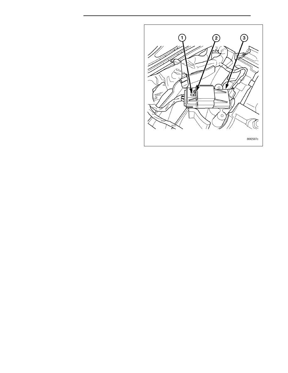
1. Disconnect electrical connector at sensor by sliding

release lock out (1). Press down on lock tab (2) for
removal.

2. Rotate

sensor

1/4

turn

counter-clockwise

for

removal.

3. Check condition of sensor o-ring.

INSTALLATION

3.7L V-6

The Manifold Absolute Pressure (MAP) sensor is mounted into the front of the intake manifold. An o-ring is used to
seal the sensor to the intake manifold.

1. Clean MAP sensor mounting hole at intake manifold.

2. Check MAP sensor o-ring seal for cuts or tears.

3. Position sensor into manifold.

4. Install MAP sensor mounting bolts (screws). Refer to Torque Specifications.

5. Connect electrical connector.

4.7L V-8

The MAP sensor is located on the front of the intake manifold. An o-ring seals the sensor to the intake manifold.

1. Clean MAP sensor mounting hole at intake manifold.

2. Check MAP sensor o-ring seal for cuts or tears.

3. Position sensor into manifold.

4. Install MAP sensor mounting bolts (screws). Refer to Torque Specifications.

5. Connect electrical connector.

5.7L V-8

The Manifold Absolute Pressure (MAP) sensor is mounted to the front of the intake manifold air plenum box.

1. Clean MAP sensor mounting hole at intake manifold.

2. Check MAP sensor o-ring seal for cuts or tears.

3. Position sensor into manifold.

4. Rotate sensor 1/4 turn clockwise for installation.

5. Connect electrical connector.

14 - 46

FUEL INJECTION

WK

SENSOR-OXYGEN

DESCRIPTION

The Oxygen Sensors (O2S) are attached to, and protrude into the vehicle exhaust system. Depending on the
engine or emission package, the vehicle may use a total of either 2 or 4 sensors.

Federal Emission Packages : Two sensors are used: upstream (referred to as 1/1) and downstream (referred to as
1/2). With this emission package, the upstream sensor (1/1) is located just before the main catalytic convertor. The
downstream sensor (1/2) is located just after the main catalytic convertor.

California Emission Packages: On this emissions package, 4 sensors are used: 2 upstream (referred to as 1/1
and 2/1) and 2 downstream (referred to as 1/2 and 2/2). With this emission package, the right upstream sensor (2/1)
is located in the right exhaust downpipe just before the mini-catalytic convertor. The left upstream sensor (1/1) is
located in the left exhaust downpipe just before the mini-catalytic convertor. The right downstream sensor (2/2) is
located in the right exhaust downpipe just after the mini-catalytic convertor, and before the main catalytic convertor.
The left downstream sensor (1/2) is located in the left exhaust downpipe just after the mini-catalytic convertor, and
before the main catalytic convertor.

REMOVAL

Refer to graphic for typical O2S (oxygen sensor) loca-
tions if equipped with four oxygen sensors.

Refer to graphic for typical O2S (oxygen sensor) loca-
tions if equipped with two oxygen sensors.

CAUTION: Never apply any type of grease to the
oxygen sensor electrical connector, or attempt any
soldering of the sensor wiring harness.

WARNING: THE EXHAUST MANIFOLD, EXHAUST
PIPES AND CATALYTIC CONVERTER BECOME
VERY HOT DURING ENGINE OPERATION. ALLOW
ENGINE TO COOL BEFORE REMOVING OXYGEN
SENSOR.

1. Raise and support vehicle.

2. Disconnect wire connector from O2S sensor.

CAUTION: When disconnecting sensor electrical connector, do not pull directly on wire going into sensor.

3. Remove O2S sensor with an oxygen sensor removal and installation tool.

4. Clean threads in exhaust pipe using appropriate tap.

WK

FUEL INJECTION

14 - 47

INSTALLATION

Threads of new oxygen sensors are factory coated with anti-seize compound to aid in removal. DO NOT add any
additional anti-seize compound to threads of a new oxygen sensor.

1. Install O2S sensor. Tighten to 30 N·m (22 ft. lbs.) torque.

2. Connect O2S sensor wire connector.

3. Lower vehicle.

THROTTLE BODY

DESCRIPTION

The throttle body is located on the intake manifold. Fuel does not enter the intake manifold through the throttle body.
Fuel is sprayed into the manifold by the fuel injectors.

OPERATION

Filtered air from the air cleaner enters the intake manifold through the throttle body. The throttle body contains an air
control passage controlled by an Idle Air Control (IAC) motor. The air control passage is used to supply air for idle
conditions. A throttle valve (plate) is used to supply air for above idle conditions.

5.7L V-8 Engine:

The throttle body on the 5.7L engine is an electrically controlled unit. A mechanical cable is not used to connect the
throttle body to the accelerator pedal. The Accelerator Pedal Position Sensor (APPS) along with inputs from other
sensors sets the throttle blade to pre-determined positions.

Except 5.7L V-8 Engine:

Certain sensors are attached to the throttle body. The accelerator pedal cable, speed control cable and transmission
control cable (when equipped) are connected to the throttle body linkage arm.

A (factory adjusted) set screw is used to mechanically limit the position of the throttle body throttle plate. Never
attempt to adjust the engine idle speed using this screw. 
All idle speed functions are controlled by the PCM.

REMOVAL

3.7L V-6

A (factory adjusted) set screw is used to mechanically
limit the position of the throttle body throttle plate.
Never attempt to adjust the engine idle speed
using this screw. 
All idle speed functions are con-
trolled by the Powertrain Control Module (PCM).

1. Remove air cleaner tube at throttle body.

2. Disconnect throttle body electrical connectors at

IAC motor and TPS.

3. Remove all control cables from throttle body (lever)

arm. Refer to the Accelerator Pedal and Throttle
Cable section for removal/installation procedures.

4. Disconnect necessary vacuum lines at throttle

body.

5. Remove three throttle body mounting bolts (2).

6. Remove throttle body from intake manifold.

14 - 48

FUEL INJECTION

WK

7. Check condition of old throttle body-to-intake man-

ifold o-ring (2).

4.7L V-8

1. Remove air duct and air resonator box at throttle

body.

2. Disconnect throttle body electrical connectors at

IAC motor and TPS (3) , (4), and (5).

3. Remove vacuum line at throttle body.

4. Remove all control cables from throttle body (lever)

arm. Refer to Accelerator Pedal and Throttle Cable.

5. Remove three throttle body mounting bolts (1).

6. Remove throttle body from intake manifold.

WK

FUEL INJECTION

14 - 49


Content   ..  1266  1267  1268  1269   ..