Jeep Grand Cherokee WJ. Manual - part 129


  Index      Jeep     Jeep Grand Cherokee WJ - service repair manual 2001 year


Search            


Content   ..  127  128  129  130   ..


Jeep Grand Cherokee WJ. Manual - part 129


REAR

The headliner washer hose (Fig. 19) is serviced

only as a unit with the headliner. If this washer hose
is damaged or faulty, the headliner unit must be
replaced. The remaining washer hoses for the rear
washer nozzle plumbing are available for service
replacement. The check valve for the rear washer
nozzle is integral to the nozzle.

(1) Using a trim stick or another suitable wide

flat-bladed tool, gently pry at the sides of the rear
washer nozzle to release the latches that secure it to
the liftgate outer panel.

(2) Pull the rear washer nozzle out from the lift-

gate outer panel far enough to access the washer
supply hose (Fig. 20).

(3) Disconnect the washer supply hose from the

barbed nipple of the rear washer nozzle.

(4) Remove the rear washer nozzle from the lift-

gate.

INSTALLATION

WINDSHIELD

(1) From the top side of the cowl grille cover,

insert the nipple end of the windshield washer nozzle
through the mounting hole in the cowl grille cover.

(2) Push firmly and evenly on the top of the wind-

shield washer nozzle until the latches snap into place
on the underside of the cowl grille cover.

(3) From the underside of the cowl grille cover,

reconnect the washer hose(s) to the barbed nipple(s)
of the windshield washer nozzle(s) or the combina-
tion wye fitting/check valve unit.

(4) Install the washer hoses for the windshield

washer nozzles or the combination wye fitting/check
valve unit into their routing clips on the underside of
the cowl grille cover.

(5) Position the cowl grille cover onto the cowl ple-

num and cowl top panels through the opening
between the hood and the windshield.

(6) Lift the left end of the cowl grille cover off of

the cowl plenum panel far enough to access the wind-
shield washer plumbing.

(7) Reconnect the windshield washer supply hose

at the in-line connector.

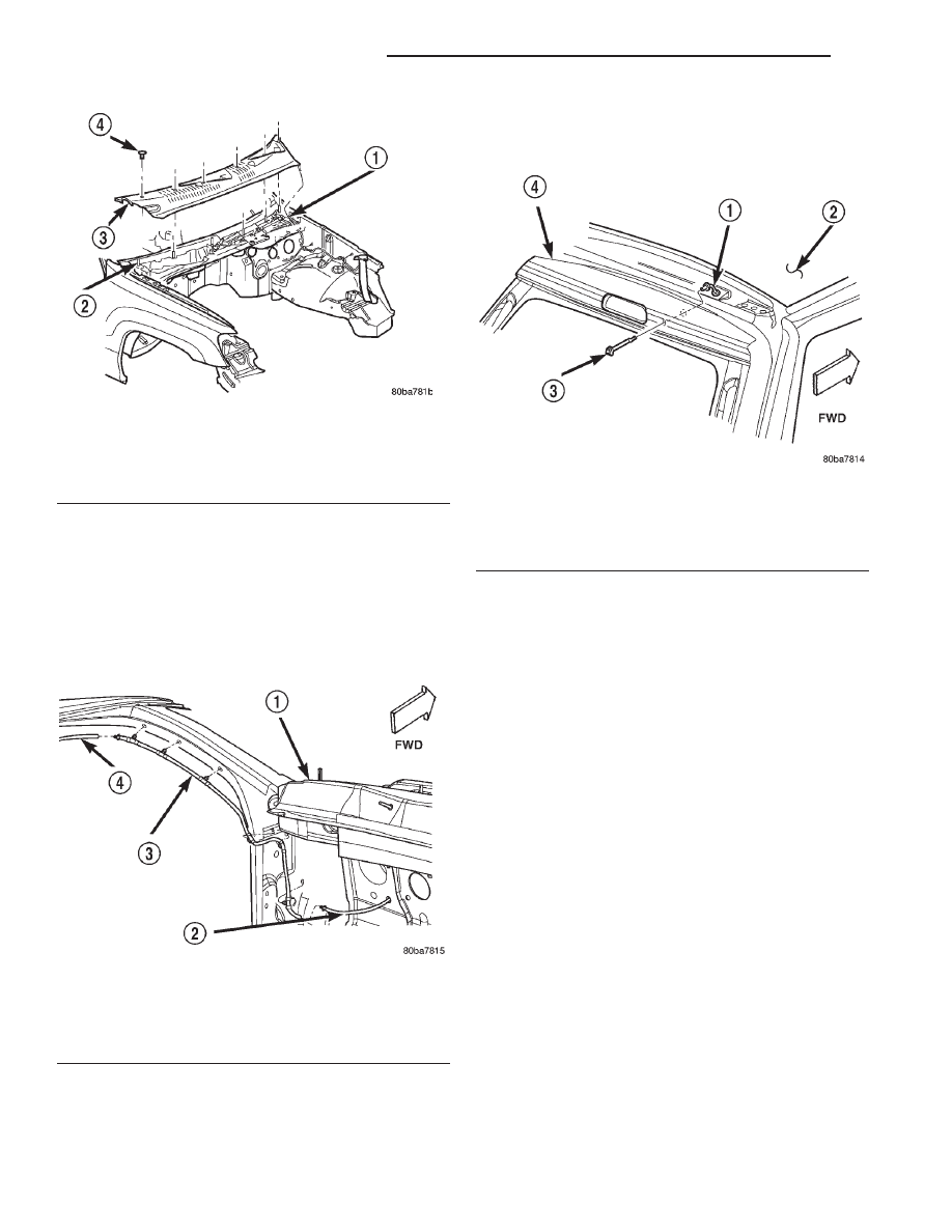
Fig. 18 Cowl Grille Cover Remove/Install

1 – WASHER HOSE CONNECTION
2 – STUDS (6)
3 – COWL GRILLE COVER
4 – PLASTIC NUT (6)

Fig. 19 Rear Washer Nozzle Plumbing

1 – UPPER COWL PLENUM PANEL
2 – WASHER HOSE FROM ENGINE COMPARTMENT
3 – A-PILLAR WASHER HOSE
4 – HEADLINER WASHER HOSE

Fig. 20 Rear Washer Nozzle Remove/Install

1 – HEADLINER WASHER HOSE
2 – ROOF PANEL
3 – WASHER NOZZLE
4 – LIFTGATE

8K - 22

WIPER AND WASHER SYSTEMS

WJ

REMOVAL AND INSTALLATION (Continued)

(8) Install the six plastic nuts that secure the cowl

grille cover to the studs on the cowl top panel near
the base of the windshield. These nuts are to be
installed by pushing them onto the studs in the fol-
lowing sequence:

(a) First, install the short nuts to the third stud

from the right, then the second stud from the left.

(b) Next, install long nuts to the right outboard

stud, then the left outboard stud.

(c) Finally, install the two remaining long nuts

to the third stud from the left, then the second
stud from the right.
(9) Starting at the ends and working toward the

center, push the hood to plenum seal onto the for-
ward flanges of the cowl grille cover and the plenum
panel.

(10) Install the wiper arms onto the wiper pivots.

Refer to Wiper Arm in the Removal and Installation
section of this group for the procedures.

(11) Reconnect and isolate the battery negative

cable.

REAR

(1) Position the rear washer nozzle to the liftgate.
(2) Reconnect the washer supply hose to the

barbed nipple of the rear washer nozzle.

(3) Insert the rear washer nozzle supply hose and

nipple into the mounting hole in the liftgate outer
panel.

(4) Push firmly and evenly on the rear washer noz-

zle until the latches snap into place on the inside of
the liftgate outer panel mounting hole.

WASHER PUMP

REMOVAL

The windshield and rear washer pumps can be

removed from the washer reservoir without removing
the reservoir from the vehicle. The same procedure is
used to remove either washer pump and motor unit.

(1) Disconnect and isolate the battery negative

cable.

(2) Raise and support the vehicle.
(3) Remove the liner from the left front fender

wheel house. Refer to Front Fender in the Removal
and Installation section of Group 23 - Body for the
procedures.

(4) Disconnect the left headlamp and dash wire

harness connector from the inoperative windshield or
rear washer pump connector receptacle (Fig. 21).

(5) Disconnect the washer hose from the barbed

outlet nipple of the inoperative washer pump and
allow the washer fluid to drain into a clean container
for reuse.

(6) Using a trim stick or another suitable wide

flat-bladed tool, gently pry the barbed inlet nipple of

the washer pump out of the rubber grommet seal in
the reservoir. Care must be taken not to damage the
reservoir.

(7) Remove the rubber grommet seal from the

washer pump mounting hole in the washer reservoir
and discard.

INSTALLATION

(1) Install a new rubber grommet seal into the

washer pump mounting hole in the washer reservoir.
Always use a new rubber grommet seal on the reser-
voir.

(2) Position the barbed inlet nipple of the washer

pump into the rubber grommet seal in the reservoir.

(3) Press firmly and evenly on the washer pump

until the barbed inlet nipple is fully seated in the
rubber grommet seal in the washer reservoir mount-
ing hole.

(4) Reconnect the washer hose to the barbed outlet

nipple of the washer pump.

(5) Reconnect the left headlamp and dash wire

harness connector to the windshield or rear washer
pump connector receptacle.

(6) Install the liner into the left front fender wheel

house. Refer to Front Fender in the Removal and
Installation section of Group 23 - Body for the proce-
dures.

(7) Lower the vehicle.
(8) Fill the washer reservoir with the washer fluid

drained from the reservoir during the removal proce-
dure.

(9) Reconnect the battery negative cable.

Fig. 21 Washer Pumps (Viewed from Bottom of

Reservoir)

1 – REAR WASHER PUMP/MOTOR
2 – WINDSHIELD WASHER PUMP/MOTOR
3 – WASHER FLUID LEVEL SWITCH

WJ

WIPER AND WASHER SYSTEMS

8K - 23

REMOVAL AND INSTALLATION (Continued)

WASHER RESERVOIR

REMOVAL

(1) Disconnect and isolate the battery negative

cable.

(2) Remove the liner from the left front fender

wheel house. Refer to Front Fender in the Removal
and Installation section of Group 23 - Body for the
procedures.

(3) Remove the air cleaner housing from the top of

the left front fender wheel house. Refer to Air
Cleaner Housing 
in the Removal and Installation
section of Group 14 - Fuel System for the procedures.

(4) Disconnect the two washer reservoir washer

hoses from the two engine compartment washer
hoses at the in-line connectors located on the top of
the left front fender wheel house (Fig. 22).

(5) Open the washer reservoir filler cap and

unsnap the filler cap hinge from the hook on the
filler neck.

(6) Remove the one screw that secures the washer

reservoir filler neck to the left inner fender shield.

(7) Raise and support the vehicle.
(8) Disconnect the left headlamp and dash wire

harness connectors from the two washer pump con-
nector receptacles (Fig. 23).

(9) Remove the two screws that secure the inboard

mounting tab of the washer reservoir to the left inner
wheel house.

(10) Pull the bottom of the washer reservoir rear-

ward far enough to access the washer fluid level sen-
sor wire harness connector on the front of the
reservoir.

(11) Disconnect the left headlamp and dash wire

harness connector from the washer fluid level sensor
connector receptacle.

(12) Pull the bottom of the washer reservoir rear-

ward far enough to disengage the outboard mounting
tab from the mounting slot on the inner fender
shield.

(13) Rotate the washer reservoir far enough so

that the inboard mounting tab clears the front sus-
pension components, then lower the reservoir far
enough to remove the filler neck from the engine
compartment.

(14) Remove the washer reservoir from the left

front fender wheel house.

INSTALLATION

(1) Position the washer reservoir into the left front

fender wheel house.

(2) Raise the washer reservoir filler neck through

the hole in the left front fender wheelhouse extension
into the engine compartment and orient the inboard
mounting tab over the top of the front suspension
components.

Fig. 22 Washer Reservoir Filler Neck Mounting

1 – WASHER RESERVOIR
2 – SCREW
3 – WASHER HOSES FROM PUMPS
4 – WASHER HOSES TO NOZZLES
5 – LEFT FENDER INNER SHIELD

Fig. 23 Washer Reservoir Remove/Install

1 – LEFT FENDER INNER SHIELD
2 – SCREW (2)
3 – WASHER PUMP WIRE HARNESS CONNECTORS
4 – WASHER FLUID LEVEL SENSOR WIRE HARNESS

CONNECTOR

5 – WASHER RESERVOIR

8K - 24

WIPER AND WASHER SYSTEMS

WJ

REMOVAL AND INSTALLATION (Continued)

(3) Pull the bottom of the washer reservoir rear-

ward far enough to engage the outboard mounting
tab with the mounting slot on the inner fender
shield.

(4) Pull the bottom of the washer reservoir rear-

ward far enough to access the washer fluid level sen-
sor connector receptacle on the front of the reservoir.

(5) Reconnect the left headlamp and dash wire

harness connector to the washer fluid level sensor
connector receptacle.

(6) Install and tighten the two screws that secure

the inboard mounting tab of the washer reservoir to
the left inner wheel house. Tighten the screws to 7.4
N·m (66 in. lbs.).

(7) Reconnect the left headlamp and dash wire

harness connectors to the two washer pump connec-
tor receptacles.

(8) Lower the vehicle.
(9) Install and tighten the one screw that secures

the washer reservoir filler neck to the left inner
fender shield. Tighten the screw to 7.4 N·m (66 in.
lbs.).

(10) Install the washer reservoir filler cap hinge

onto the hook on the filler neck and close the cap.

(11) Reconnect the two washer reservoir washer

hoses to the two engine compartment washer hoses
at the in-line connectors located on the top of the left
front fender wheel house.

(12) Install the air cleaner housing onto the top of

the left front fender wheel house. Refer to Air
Cleaner Housing 
in the Removal and Installation
section of Group 14 - Fuel System for the procedures.

(13) Install the liner into the left front fender

wheel house. Refer to Front Fender in the Removal
and Installation section of Group 23 - Body for the
procedures.

(14) Reconnect the battery negative cable.

WASHER FLUID LEVEL SENSOR

REMOVAL

The washer fluid level sensor can be removed from

the washer reservoir without removing the reservoir
from the vehicle.

(1) Disconnect and isolate the battery negative

cable.

(2) Remove the one screw that secures the washer

reservoir filler neck to the left inner fender shield.

(3) Raise and support the vehicle.
(4) Remove the liner from the left front fender

wheel house. Refer to Front Fender in the Removal
and Installation section of Group 23 - Body for the
procedures.

(5) Disconnect the washer hose from the barbed

outlet nipple of the rearmost (windshield) washer

pump and allow the washer fluid to drain into a
clean container for reuse.

(6) Remove the two screws that secure the inboard

mounting tab of the washer reservoir to the left inner
wheel house.

(7) Pull the bottom of the washer reservoir rear-

ward far enough to access the washer fluid level sen-
sor wire harness connector on the front of the
reservoir.

(8) Disconnect the left headlamp and dash wire

harness connector from the washer fluid level sensor
connector receptacle.

(9) Using a trim stick or another suitable wide

flat-bladed tool, gently pry the barbed nipple of the
washer fluid level sensor out of the rubber grommet
seal on the front of the reservoir (Fig. 24). Care must
be taken not to damage the reservoir.

(10) Remove the washer fluid level sensor and

float from the washer reservoir.

(11) Remove the rubber grommet seal from the

washer fluid level sensor mounting hole in the
washer reservoir and discard.

INSTALLATION

(1) Install a new rubber grommet seal into the

washer fluid level sensor mounting hole in the front
of the washer reservoir. Always use a new rubber
grommet seal on the reservoir.

Fig. 24 Washer Fluid Level Sensor Remove/Install

1 – WASHER RESERVOIR
2 – WASHER FLUID LEVEL SENSOR
3 – GROMMET SEAL

WJ

WIPER AND WASHER SYSTEMS

8K - 25

REMOVAL AND INSTALLATION (Continued)


Content   ..  127  128  129  130   ..