Jeep Grand Cherokee WJ. Manual - part 127


  Index      Jeep     Jeep Grand Cherokee WJ - service repair manual 2001 year


Search            


Content   ..  125  126  127  128   ..


Jeep Grand Cherokee WJ. Manual - part 127


times. Check for continuity between the cavity for
terminal 85 of the wiper high/low relay and a good
ground. If OK, refer to Wiper On/Off Relay in the
Diagnosis and Testing section of this group. If not
OK, repair the open ground circuit to ground as
required.

WIPER ON/OFF RELAY

The wiper on/off relay (Fig. 4) is located in the

Power Distribution Center (PDC) between the bat-
tery and the fender on the right side of the engine
compartment. See the fuse and relay layout label
affixed to the inside surface of the PDC cover for
wiper on/off relay identification and location. For
complete circuit diagrams, refer to Wipers in the
Contents of Group 8W - Wiring Diagrams.

(1) Remove the wiper on/off relay from the PDC.

Refer to Wiper Relays in the Removal and Installa-
tion section of this group for the procedures.

(2) A relay in the de-energized position should

have continuity between terminals 87A and 30, and
no continuity between terminals 87 and 30. If OK, go
to Step 3. If not OK, replace the faulty relay.

(3) Resistance between terminals 85 and 86 (elec-

tromagnet) should be 75

6 5 ohms. If OK, go to Step

4. If not OK, replace the faulty relay.

(4) Connect a battery to terminals 85 and 86.

There should now be continuity between terminals
30 and 87, and no continuity between terminals 87A
and 30. If OK, perform the Relay Circuit Test that
follows. If not OK, replace the faulty relay.

RELAY CIRCUIT TEST

(1) The relay common feed terminal cavity (30) is

connected to the common feed terminal of the wiper
high/low relay. When the wiper on/off relay is de-en-
ergized, this terminal connects the wiper park switch
sense circuit to the wiper high/low relay. When the
wiper on/off relay is energized, this terminal connects

the fused ignition switch output from the wiper sys-
tem circuit breaker to the wiper high/low relay. There
should be continuity between the cavity for terminal
30 of the wiper on/off relay and the cavity for termi-
nal 30 of the wiper high/low relay at all times. If OK,
go to Step 2. If not OK, repair the open wiper on/off
relay output circuit to the common feed terminal cav-
ity for the wiper high/low relay in the PDC as
required.

(2) The relay normally closed terminal (87A) is

connected to the wiper park switch sense circuit.
There should be continuity between the cavity for
terminal 87A of the wiper on/off relay and the wiper
park switch sense circuit cavity of the windshield
wiper motor connector at all times. If OK, go to Step
3. If not OK, repair the open wiper park switch sense
circuit to the windshield wiper motor as required.

(3) The relay normally open terminal (87) is con-

nected to the fused ignition switch output circuit.
There should be battery voltage at the cavity for ter-
minal 87 of the wiper on/off relay when the ignition
switch is in the On or Accessory positions. If OK, go
to Step 4. If not OK, repair the open fused ignition
switch output circuit to the wiper system circuit
breaker in the junction block as required.

(4) The coil battery terminal (86) is also connected

to the fused ignition switch output circuit. There
should be battery voltage at the cavity for terminal
86 of the wiper on/off relay when the ignition switch
is in the On or Accessory positions. If OK, go to Step
5. If not OK, repair the open fused ignition switch
output circuit to the wiper system circuit breaker in
the junction block as required.

(5) The coil ground terminal (85) is connected to

the wiper on/off relay control circuit. It is grounded
by the Body Control Module (BCM) to energize the
wiper

on/off

relay.

There

should

be

continuity

between the cavity for terminal 85 of the wiper on/off
relay and the wiper on/off relay control circuit cavity
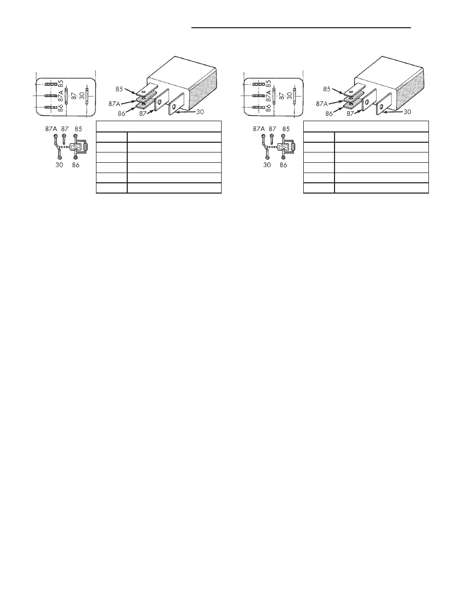
TERMINAL LEGEND

NUMBER

IDENTIFICATION

30

COMMON FEED

85

COIL GROUND

86

COIL BATTERY

87

NORMALLY OPEN

87A

NORMALLY CLOSED

Fig. 3 Wiper High/Low Relay

TERMINAL LEGEND

NUMBER

IDENTIFICATION

30

COMMON FEED

85

COIL GROUND

86

COIL BATTERY

87

NORMALLY OPEN

87A

NORMALLY CLOSED

Fig. 4 Wiper On/Off Relay

8K - 14

WIPER AND WASHER SYSTEMS

WJ

DIAGNOSIS AND TESTING (Continued)

of the 26-way instrument panel wire harness connec-
tor for the BCM at all times. If OK, use a DRB scan
tool and the proper Diagnostic Procedures manual to
diagnose the BCM. If not OK, repair the open wiper
on/off relay control circuit to the BCM as required.

REMOVAL AND INSTALLATION

WIPER BLADE

REMOVAL

WINDSHIELD

(1) Lift the wiper arm and blade off of the wind-

shield glass until the wiper arm hinge is in its over-
center position.

(2) Depress the latch release tab located on the

bottom of the plastic wiper blade pivot block near the
center of the blade and at the end of the wiper arm
(Fig. 5).

(3) Slide the wiper blade down the wiper arm

towards the wiper pivot at the base of the wind-
shield.

(4) Push the lower end of the wiper blade away

from the underside of the wiper arm far enough for
the plastic wiper blade pivot block to clear the hook
formation on the end of the arm.

(5) Disengage the wiper blade from the wiper arm.

REAR

(1) Disengage the rear wiper arm support from the

rubber rear wiper arm park ramp on the right side of
the liftgate just below the flip-up glass.

(2) Lift the wiper arm and blade away from the

liftgate until the wiper arm hinge is in its over-center
position.

(3) Depress the latch release tab located on the

bottom of the plastic wiper blade pivot block near the
center of the blade and at the end of the wiper arm
(Fig. 5).

(4) Slide the wiper blade down the wiper arm

towards the rear wiper motor output shaft below the
center of the liftgate flip-up glass.

(5) Push the lower end of the wiper blade away

from the underside of the wiper arm far enough for
the plastic wiper blade pivot block to clear the hook
formation on the end of the arm.

(6) Disengage the wiper blade from the wiper arm.

INSTALLATION

WINDSHIELD

(1) Position the wiper blade to the underside of the

wiper arm.

NOTE: The notched retainer end of the wiper ele-
ment should always be oriented towards the end of
the wiper blade that is nearest to the wiper pivot.

(2) Engage the wiper blade pivot block with the

hook formation on the end of the wiper arm.

(3) Slide the wiper blade up the wiper arm

towards the hook formation until the plastic pivot
block latch has fully engaged. Latch engagement will
be accompanied by an audible click.

(4) Lower the wiper arm and blade gently onto the

windshield glass.

REAR

(1) Position the wiper blade to the underside of the

wiper arm.

NOTE: The notched retainer end of the wiper ele-
ment should always be oriented towards the end of
the wiper blade that is nearest to the rear wiper
motor output shaft.

(2) Engage the wiper blade pivot block with the

hook formation on the end of the wiper arm.

(3) Slide the wiper blade up the wiper arm

towards the hook formation until the plastic pivot
block latch has fully engaged. Latch engagement will
be accompanied by an audible click.

(4) Lower the wiper arm and blade gently onto the

liftgate rear wiper arm park ramp.

WIPER ARM

REMOVAL

WINDSHIELD

(1) Carefully pry the plastic nut cap off of the

pivot end of the wiper arm (Fig. 6).

(2) Remove the nut that secures the wiper arm to

the wiper pivot shaft.

(3) Use a battery terminal puller to disengage the

wiper arm from the wiper pivot shaft splines (Fig. 7).

Fig. 5 Wiper Blade Remove/Install - Typical

1 – RELEASE TAB

WJ

WIPER AND WASHER SYSTEMS

8K - 15

DIAGNOSIS AND TESTING (Continued)

(4) Remove the wiper arm and blade from the base

of the windshield.

REAR

(1) Unsnap the rear wiper arm pivot cover by lift-

ing it at the rear wiper motor output shaft end of the
arm (Fig. 8).

(2) Remove the nut that secures the wiper arm to

the rear wiper motor output shaft.

(3) Use a battery terminal puller to disengage the

wiper arm from the rear wiper motor output shaft
splines (Fig. 7).

(4) Remove the rear wiper arm and blade from the

liftgate.

INSTALLATION

WINDSHIELD

NOTE: Always install the wiper arm and blade with
the wiper motor in the Park position.

(1) Place the wiper arm and blade onto the base of

the windshield with the pivot hole on the end of the
arm positioned over the wiper pivot shaft.

(2) Align the lower edge of the blade with the

wiper alignment lines located in the lower edge of
the windshield glass (Fig. 6).

(3) With the wiper blade aligned, push the pivot

hole on the end of the wiper arm down over the
wiper pivot shaft.

(4) Install and tighten the nut that secures the

wiper arm to the wiper pivot shaft. Tighten the nut
to 23.7 N·m (210 in. lbs.).

(5) Operate the wipers with the windshield glass

wet, then turn the wiper switch to the Off position.
Check for correct wiper blade alignment and readjust
if required.

(6) Install the plastic nut cap onto the wiper arm

pivot nut.

REAR

NOTE: Always install the wiper arm and blade with
the wiper motor in the Park position.

Fig. 6 Wiper Arm Remove/Install

1 – ARM AND BLADE
2 – CAP
3 – NUT
4 – PIVOT SHAFT
5 – ALIGNMENT LINE

Fig. 7 Wiper Arm Puller - Typical

1 – WIPER ARM
2 – WIPER PIVOT
3 – BATTERY TERMINAL PULLER

Fig. 8 Rear Wiper Arm Remove/Install

1 – LIFTGATE
2 – REAR WIPER MOTOR OUTPUT SHAFT
3 – PARK RAMP
4 – PIVOT COVER
5 – WIPER ARM
6 – NUT

8K - 16

WIPER AND WASHER SYSTEMS

WJ

REMOVAL AND INSTALLATION (Continued)

(1) Place the wiper arm and blade onto the liftgate

with the wiper arm support positioned on the park
ramp and the pivot hole on the end of the arm posi-
tioned over the rear wiper motor output shaft.

(2) Position the ridge of the wiper arm support on

the liftgate park ramp in the Installation Position
(Fig. 9).

(3) With the wiper arm in the Installation Posi-

tion, push the pivot hole on the end of the wiper arm
down over the rear wiper motor output shaft.

(4) Install and tighten the nut that secures the

wiper arm to the rear wiper motor output shaft.
Tighten the nut to 18 N·m (160 in. lbs.).

(5) Close the rear wiper pivot cover back over the

rear wiper arm mounting nut.

(6) Lift the rear wiper arm and blade away from

the liftgate park ramp and place the wiper arm sup-
port in the Park Position (Fig. 9).

REAR WIPER ARM PARK RAMP

REMOVAL

(1) Disengage the rear wiper arm support from the

rubber rear wiper arm park ramp on the right side of
the liftgate just below the flip-up glass.

(2) Lift the wiper arm and blade away from the

liftgate until the wiper arm hinge is in its over-center
position.

(3) Remove the screw that secures the park ramp

to the liftgate (Fig. 10).

(4) Remove the rear wiper arm park ramp from

the liftgate.

INSTALLATION

(1) Position the rear wiper arm park ramp onto

the liftgate.

(2) Install and tighten the screw that secures the

park ramp to the liftgate. Tighten the screw to 6.8
N·m (60 in. lbs.).

(3) Lower the wiper arm and blade gently onto the

liftgate rear wiper arm park ramp.

WINDSHIELD WIPER MOTOR, PIVOT AND
LINKAGE MODULE

REMOVAL

(1) Disconnect and isolate the battery negative

cable.

(2) Remove the wiper arms from the wiper pivots.

Refer to Wiper Arm in the Removal and Installation
section of this group for the procedures.

Fig. 9 Rear Wiper Arm Installation

1 – LIFTGATE
2 – PARK RAMP
3 – WIPER ARM
4 – INSTALLATION POSITION
5 – WIPER ARM AND BLADE
6 – PARK POSITION
7 – PARK RAMP
8 – LIFTGATE

Fig. 10 Rear Wiper Arm Park Ramp Remove/Install

1 – RIVET NUT
2 – SCREW
3 – PARK RAMP
4 – LIFTGATE

WJ

WIPER AND WASHER SYSTEMS

8K - 17

REMOVAL AND INSTALLATION (Continued)


Content   ..  125  126  127  128   ..