Engine Iveco C10/C13/C78/Cursor 13/Cursor 78. Manual - part 92
EDC control unit PIN-OUT
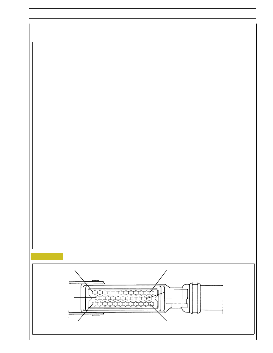
Connector “B” (Frame area)
Figure 91
SECTION 3 - INDUSTRIAL APPLICATION
35
Pin
Functions
1 - Negative direct from battery / blink button — code
2 - Negative direct from battery / blink button — code
3 - Positive from main remote switch
4 - Positive from main remote switch
5 - Signal for electronic rev. counter (if available)
6 - Negative for EDC / blink button — code warning light (if available)
7 - CAN line for Multiplex electric system architecture
8 - ---
9 - Engine phase signal for diagnosis connector
10 - Negative for pre-post heating remote switch engagement
11 - CAN - L line for interconnection of the CAN line with control units (if any) available with the application
12 - CAN - H line for interconnection of the CAN line with control units (if any) available with the application
13 - K line for diagnosis connector
14 - ---
15 - Key controlled supply positive
16 - Accelerator pedal position sensor supply
17 - Negative from idler switch
18 - Negative for warning light pre — post heating
19 - ---
20 - Positive from N.C. clutch switch (if available)
21 - Function “RESUME” Cruise Control (if available)
22 - Positive from speed reducer switch (if available)
23 - Accelerator pedal position signal sensor
24 - L line for diagnosis connector
25 - Negative for accelerator pedal, multiple-state switch for torque reducer and negative for engine speed and vehicle
speed sensors
26 - Positive from primary N.C. brake switch
27 - Negative for main remote switch
28 - Signal from the multiple-state switch for the torque reducer (if available)
29 - Vehicle speed (D3 tachograph) signal (if available)
30 - PWM line
31 - Positive from N.C. redundant brake switch
32 - Function “SET —“ Cruise Control (if available)
33 - Function “OFF +” Cruise Control (if available)
34 - Function “SET +” Cruise Control (if available)
35 - Negative for accelerator pedal position sensor
WIRING DIAGRAM OF EDC CONTROL UNIT WITH CONNECTIONS TO CONNECTOR ”B”
1
13
24
35
000576t
12
23