Engine Iveco C10/C13/C78/Cursor 13/Cursor 78. Manual - part 48
99367
Figure 33
Figure 34
Figure 35
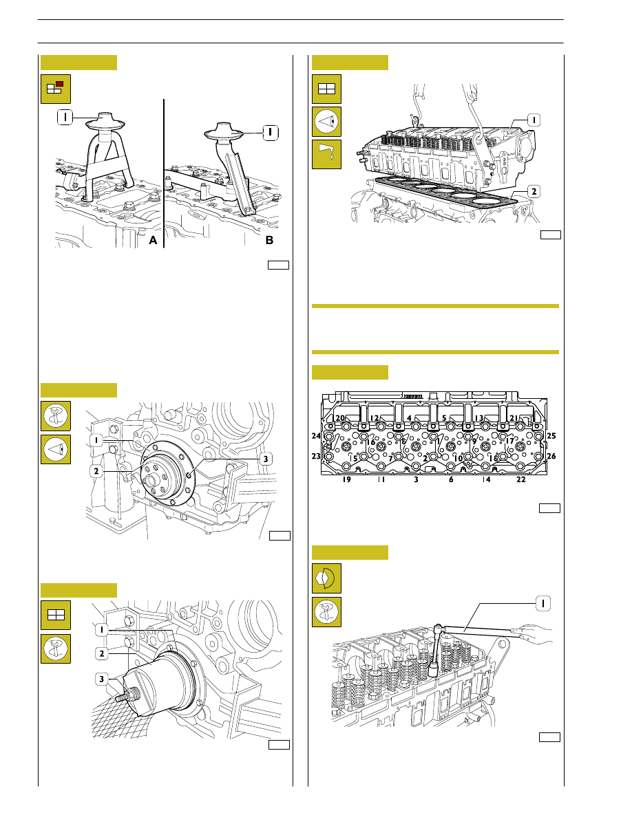
Figure 36
Figure 37
Figure 38
Undo the screws and remove the suction strainer (1).
A. for types: F3AE0684E*B002 - F3AE0684J*B902.
B. for types: F3AE0684D*B001 - F3AE0684G*B003
F3AE0684D*B003.
Using the centring ring 99396035 (2), check the exact position
of the cover (1). If it is wrong, proceed accordingly and lock
the screws (3).
Key on the gasket (1), mount the key 99346250 (2) and,
screwing down the nut (3), drive in the gasket (1).
Check that the pistons 1-6 are exactly at the T.D.C.
Put the gasket (2) on the crankcase.
Mount the cylinder head (1) and tighten the screws as shown
in Figs. 38 - 39 - 40.
Diagram of the tightening sequence of the screws fixing the
cylinder head.
- Pre-tightening with the torque wrench (1):
1
st
phase: 60 Nm (6 kgm).
2
nd
phase: 120 Nm (12 kgm).
60563
60564
60515
60565
61270
Lubricate the thread of the screws with engine oil
before assembly.
ENGINE ASSEMBLY
NOTE
14
SECTION 3 - INDUSTRIAL APPLICATION