Engine Iveco C10/C13/C78/Cursor 13/Cursor 78. Manual - part 49
60572
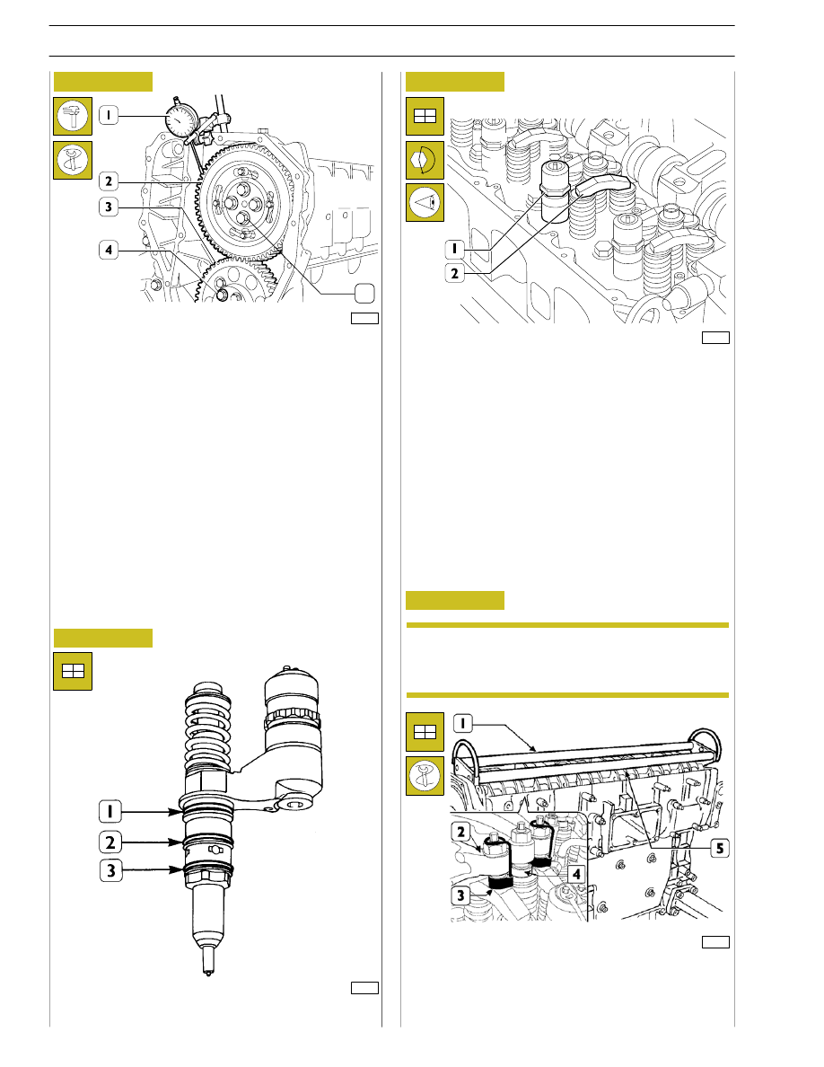
Figure 51
Figure 52
Position the gear (2) on the camshaft so that the 4 slots are
centred with the holes for fixing the camshaft, without fully
locking the screws (5).
Using the dial gauge with a magnetic base (1), check that the
clearance between the gears (2 and 3) is 0.073 — 0.195 mm;
if this is not so, adjust the clearance as follows:
- Loosen the screws (4) fixing the idle gear (3).
- Loosen the screw (2, Figure 49) fixing the link rod. Shift
the link rod (3, Figure 49) to obtain the required
clearance.
- Lock the screw (2, Figure 49) fixing the link rod and
screws (4, Figure 51) fixing the idle gear to the required
torque.
Figure 53
44908
Fit the seals (1) (2) (3) on the injectors.
Before refitting the rocker-arm shaft assembly,
make sure that all the adjustment screws have been
fully unscrewed.
Using tool 99360144 (3), fasten the blocks (4) to the rocker
arms (2).
Apply the tool 99360553 (1) to the rocker arm shaft (5) and
mount the shaft on the cylinder head.
73533
5
Fitting pump-injectors
Fitting rocker-arm shaft assembly
Mount:
- The injectors (1) and, using a torque wrench, lock the
bracket fixing screws to a torque of 26 Nm.
- The crosspieces (2) on the valve stem, all with the largest
hole on the same side.
Figure 54
99284
NOTE
18
SECTION 3 - INDUSTRIAL APPLICATION