Isuzu Amigo / Axiom / Trooper / Rodeo / VehiCross. Manual - part 538


  Index      Isuzu     Isuzu Amigo / Axiom / Trooper / Rodeo / VehiCross - service repair manual 1999-2002 year


Search            


Content   ..  536  537  538  539   ..


Isuzu Amigo / Axiom / Trooper / Rodeo / VehiCross. Manual - part 538


1A–20 HEATING, VENTILATION AND AIR CONDITIONING (HVAC)
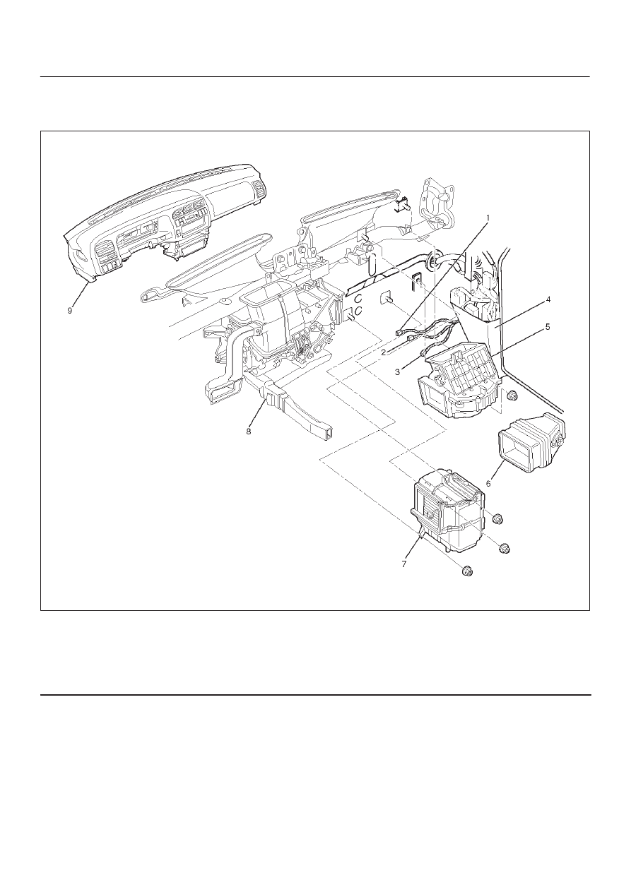
Blower Assembly

Blower Assembly and Associated Parts

873RY00003

Legend

(1) Electro Thermo Connector
(2) Blower Motor Connector
(3) Resistor Connector
(4) Dash Side Trim Panel (RH)

(5) Blower Assembly
(6) Duct
(7) Evaporator Assembly (A/C only)
(8) Heater Unit
(9) Instrument Panel Assembly

Removal

1. Disconnect the battery ground cable.
2. Discharge and recover refrigerant (with air

conditioning).

D

Refer to Refrigerant Recovery in this section.

3. Remove instrument panel assembly.

D

Refer to Instrument Panel Assembly in Body and
Accessories section.

4. Disconnect resistor connector.
5. Remove duct.
6. Remove evaporator assembly (A/C only).

D

Refer to Evaporator Assembly in this section.

7. Remove dash side trim panel (RH).
8. Disconnect blower motor connector.
9. Remove blower assembly.

HEATING, VENTILATION AND AIR CONDITIONING (HVAC) 1A–21

Installation

To install, follow the removal steps in the reverse order,
noting the following point:

1. Adjust the control lever assembly cables.

D

Refer to Control Lever Assembly in this section.

Blower Link Unit and / or Mode door

Disassembled View

873RS001

Legend

(1) Upper Case
(2) Mode Door
(3) Lower Case

(4) Sub Lever
(5) Door Lever
(6) Blower Assembly

Removal

1. Disconnect the battery ground cable.
2. Discharge and recover refrigerant (with air

conditioning).

D

Refer to Refrigerant Recovery in this section.

3. Remove blower assembly.

D

Refer to Blower Assembly in this section.

1A–22 HEATING, VENTILATION AND AIR CONDITIONING (HVAC)

4. Remove lower case.
5. Separate the upper case and slit the lining parting

face with a knife.

873RS002

6. Pull out the mode door while lifting up the catch of

door lever.

7. Remove sub-lever.
8. Remove door lever.

Installation

To install, follow the removal steps in the reverse order,
noting the following points:

1. Apply grease to the door lever and to the abrasive

surface of the upper case.

2. Apply an adhesive to the parting face of the lining

when assembling the upper case.

HEATING, VENTILATION AND AIR CONDITIONING (HVAC) 1A–23

Blower Motor

Blower Motor and Associated Parts

873R200006

Legend

(1) Blower Motor Connector

(2) Blower Motor Assembly
(3) Attaching Screw

Removal

1. Disconnect the battery ground cable.
2. Remove blower motor connector.
3. Remove attaching screw.
4. Remove blower motor assembly.

Installation

To install, follow the removal steps in the reverse order.


Content   ..  536  537  538  539   ..