Isuzu Amigo / Axiom / Trooper / Rodeo / VehiCross. Manual - part 536


  Index      Isuzu     Isuzu Amigo / Axiom / Trooper / Rodeo / VehiCross - service repair manual 1999-2002 year


Search            


Content   ..  534  535  536  537   ..


Isuzu Amigo / Axiom / Trooper / Rodeo / VehiCross. Manual - part 536


1A–12 HEATING, VENTILATION AND AIR CONDITIONING (HVAC)

Chart “E” Blower Motor Dose Not Run At High Position 

Step

Action

Yes

No

1

Is resistor OK?

Go to Step 2

Replace

2

Is fan control knob (Fan Switch) OK?

Open circuit

between Chassis

side connector

terminal No. I41-3

and No. I18-6.

Replace control

lever assembly.

Chart “F” Blower Motor Does Not Stop In The “OFF” Position 

Step

Action

Yes

No

1

Is the fan control knob (Fan Switch) OK?

Short circuit

between chassis

side connector

terminal No. B5-2

and

No. I41-2,No. I41

-3 and No. I18-6,

No. I41-6 and

No. I18-3,

No. I41-4 and

No. I18-5 or

No. I41-1 and

No. I18-2

Replace control

lever assembly.

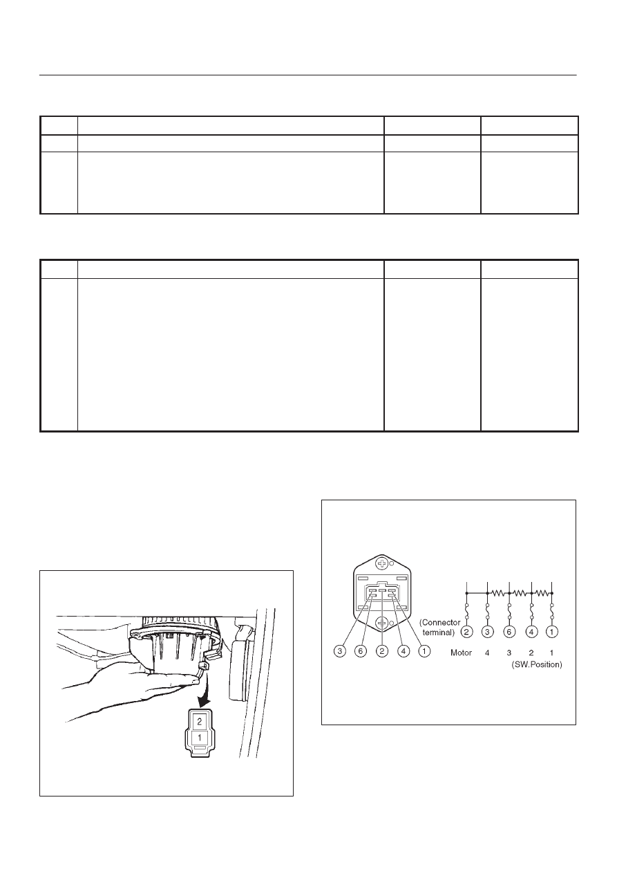
Individual Inspection

Blower Motor

1. Disconnect the blower motor (B-5) connector from

the blower motor.

2.  Connect the battery positive terminal to the No. 1

terminal of the blower motor and the negative to the
No. 2.

3. Be sure to check to see if the blower motor operates

correctly.

873RS005

Resistor

1. Disconnect the resistor (I-41) connector.
2. Check for continuity and resistance between the

terminals of the resistor.

840R200011

HEATING, VENTILATION AND AIR CONDITIONING (HVAC) 1A–13

Fan switch

position

Resistor terminals

with continuity

Resistance

1

1 — 2

2.4 

W

2

2 — 4

0.90 

W

3

2 — 6

0.28 

W

4

2 — 3

Fan Control Knob (Fan Switch)

1. Check for continuity between the terminals of the fan

switch.

865RS001

Fan switch

position

Switch connector terminals with con-

tinuity

OFF

No continuity

1

1 – 2 – 4

2

1 – 4 – 5

3

1 – 3 – 4

4

1 – 4 – 6

Heater & A/C Relay

1. Disconnect the heater and the A/C relay (B-36).

D

When removing the connector for relay, unfasten
the tang lock of the connector by using a
screwdriver, then pull the relay (1) out.

825RS001

2. Check for continuity between the heater and the A/C

relay (B-36) terminals.

825RS002

Condition

Relay terminals with

continuity

Normal

1 – 3 (Approx 85–105

W

)

When battery voltage is

applied between 1 – 3

2 – 4

1A–14 HEATING, VENTILATION AND AIR CONDITIONING (HVAC)

Heater Unit

Heater Unit and Associated Parts

860RY00005

Legend

(1) Instrument Panel Assembly
(2) Instrument Panel Center Bracket
(3) Resistor
(4) Duct
(5) Evaporator Assembly (A/C only)
(6) Rear Heater Duct

(7) Heater Unit Assembly
(8) Center Ventilation Lower Duct
(9) Driver Lap Vent Nozzle

(10) Water Hose

(11) Electro Thermo Connector (With A/C)

(12) Resistor Connector

HEATING, VENTILATION AND AIR CONDITIONING (HVAC) 1A–15

Removal

1. Disconnect the battery ground cable.
2. Drain the engine coolant.
3. Discharge and recover refrigerant (with air

conditioning)

D

Refer to Refrigerant Recovery in this section.

4. Remove the Instrument panel assembly.

D

Refer to Instrument Panel Assembly in Body and
Accessories section.

5. Disconnect the water hoses at the heater unit.
6. Disconnect resistor connector.
7. Remove duct.
8. Remove evaporator assembly (A/C only).

D

Refer to Evaporator Assembly in this section.

9. Remove instrument panel center bracket.

D

Refer to Cross Beam Assembly in Body and
Accessories section.

10. Remove rear heater duct.

11. Remove heater unit assembly.

12. Remove driver lap vent nozzle.
13. Remove center ventilation lower duct.

Installation

To install, follow the removal steps in the reverse order,
noting the following points:

1. When handling the PCM and the control unit, be

careful not to make any improper connection of the
connectors.

2. Adjust the control lever assembly cables.

D

Refer to Control Lever Assembly in this section.

3. When installing the heater unit, defroster nozzle and

center vent duct, be sure that the proper seal is made,
without any gap between them.


Content   ..  534  535  536  537   ..