Isuzu Amigo / Axiom / Trooper / Rodeo / VehiCross. Manual - part 537


  Index      Isuzu     Isuzu Amigo / Axiom / Trooper / Rodeo / VehiCross - service repair manual 1999-2002 year


Search            


Content   ..  535  536  537  538   ..


Isuzu Amigo / Axiom / Trooper / Rodeo / VehiCross. Manual - part 537


1A–16 HEATING, VENTILATION AND AIR CONDITIONING (HVAC)

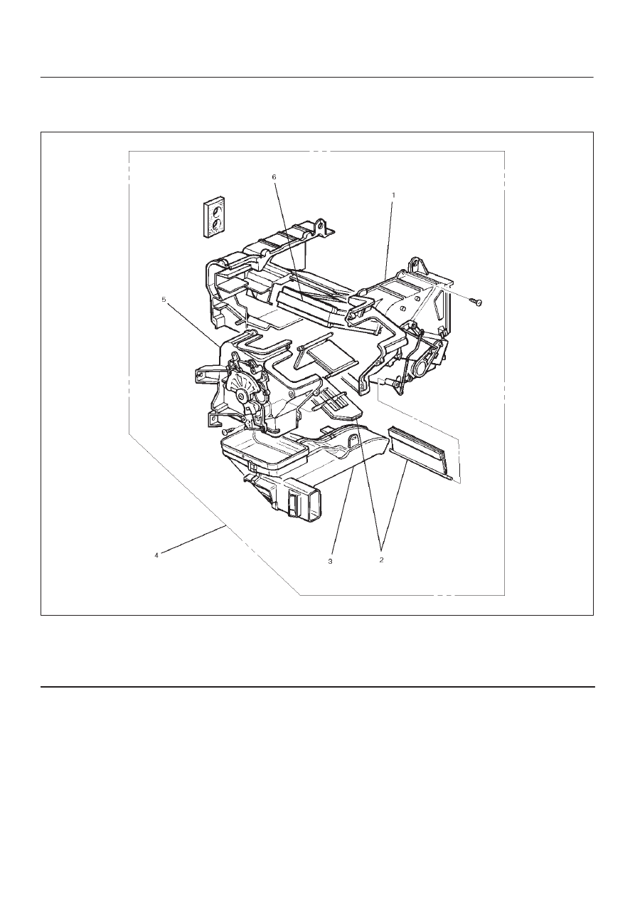
Heater Core and / or Mode Door

Disassembled View

860RS001

Legend

(1) Case (Temperature Control)
(2) Mode Door
(3) Duct

(4) Heater Unit
(5) Case (Mode Control)
(6) Heater Core

Removal

1. Disconnect the battery ground cable.
2. Drain the engine coolant.
3. Discharge and recover refrigerant (with air

conditioning).

D

Refer to Refrigerant Recovery in this section.

4. Remove heater unit.

D

 Refer to Heater Unit in this section.

5. Remove duct.

6. Remove case (Mode control) and do not remove link

unit at this step.

HEATING, VENTILATION AND AIR CONDITIONING (HVAC) 1A–17

7. Remove case (Temperature control). Separate two

halves of core case.

860R200007

8. Remove heater core (1).

860R200006

9. Pull out the mode door while raising up the catch of

the door lever.

860RS004

Inspection

Check for foreign matter in the heater core, stains or core
fin damage.

Installation

To install, follow the removal steps in the reverse order,
noting the following point:

1. Check that each mode door operates properly.

1A–18 HEATING, VENTILATION AND AIR CONDITIONING (HVAC)

Heater Mode Control Link Unit

Disassembled View

860RS005

Legend

(1) Case (Mode Control)
(2) Heater Unit
(3) Mode Sub-lever

(4) Clip
(5) Door Lever
(6) Rod
(7) Washer and Mode Main Lever

Removal

1. Disconnect the battery ground cable.
2. Drain engine coolant.
3. Discharge and recover refrigerant (with air

conditioning).

D

Refer to Refrigerant Recovery in this section.

4. Remove heater unit.

D

Refer to Heater Unit in this section.

5. Remove the case (Mode control) from heater unit.
6. Remove washer and the mode main lever.
7. Remove rod.
8. Press the tab of the sub-lever inward, and take out the

sub-lever.

9. Pull out the door lever while raising up the catch of the

door lever.

860RS006

10. Remove clip.

HEATING, VENTILATION AND AIR CONDITIONING (HVAC) 1A–19

Installation

To install, follow the remove steps in the reverse order,
noting the following points:

1. Apply grease to the mode sub-lever and to the

abrasive surface of the heater unit.

2. After installing the link unit, check to see if the link unit

operates correctly.

Heater Temperature Control Link Unit

Disassembled View

860RS007

Legend

(1) Case (Temperature control)
(2) Clip
(3) Door Lever

(4) Clip
(5) Heater Unit
(6) Rod
(7) Sub-lever

Removal

1. Disconnect the battery ground cable.
2. Drain engine coolant.
3. Discharge and recover refrigerant (with air

conditioning).

D

Refer to Refrigerant Recovery in this section.

4. Remove heater unit.

D

Refer to Heater Unit in this section.

5. Remove the case (Temperature control) from the

heater unit.

6. Remove rod.
7. Remove sub-lever.

8. Pull out the door lever while raising up the catch of the

door lever.

9. Remove clip.

Installation

To install, follow the removal steps in the reverse order,
noting the following points:

1. Apply grease to the sub-lever and to the abrasive

surface of the heater unit.

2. After installing the link unit, check to see if the link unit

operates correctly.


Content   ..  535  536  537  538   ..