Isuzu Amigo / Axiom / Trooper / Rodeo / VehiCross. Manual - part 534
1A–4
HEATING, VENTILATION AND AIR CONDITIONING (HVAC)
640R200001
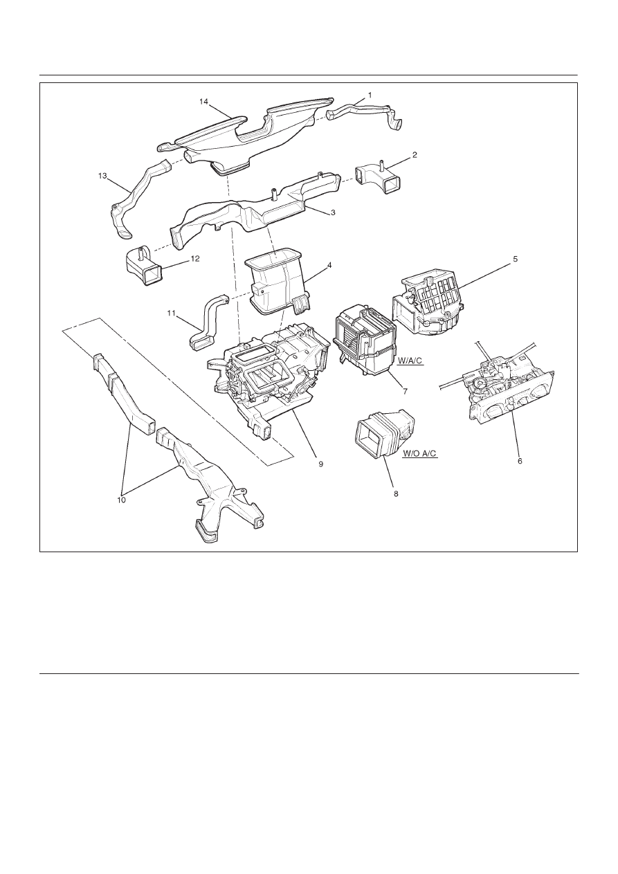
Legend
(1) Side Defroster Hose
(2) Vent Box
(3) Upper Center Vent Box
(4) Lower Center Vent Box
(5) Blower Assembly
(6) Control Lever Assembly
(7) Evaporator Assembly
(8) Duct
(9) Heater Unit
(10) Rear Heater Duct
(11) Lap Vent Nozzle
(12) Vent Box
(13) Side Defroster Hose
(14) Defroster Nozzle