Isuzu Amigo / Axiom / Trooper / Rodeo / VehiCross. Manual - part 533


  Index      Isuzu     Isuzu Amigo / Axiom / Trooper / Rodeo / VehiCross - service repair manual 1999-2002 year


Search            


Content   ..  531  532  533  534   ..


Isuzu Amigo / Axiom / Trooper / Rodeo / VehiCross. Manual - part 533


0B–12

MAINTENANCE AND LUBRICATION

Maintenance Service Data

Service Data and Specifications
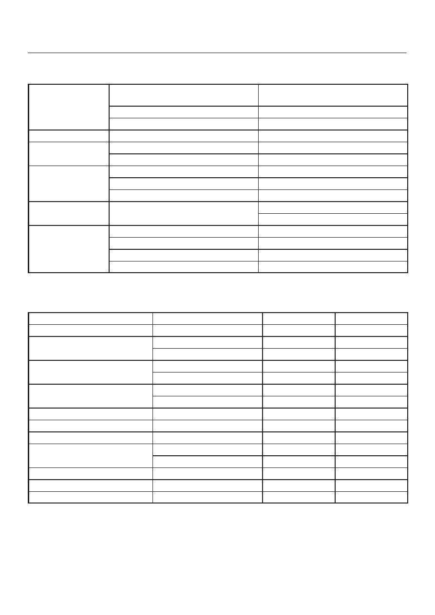
ENGINE

Valve clearance (cold)

Intake 0.28

±

0.05 mm (0.011

±

0.002 in)

Exhaust 0.3

±

0.05 mm (0.012

±

0.002 in)

Spark plug type

K16PR-P11/PK16PR11/RC10PYP4

Spark plug gap

1.05 mm (0.04 in)

CLUTCH

Clutch pedal free play

5–15 mm (0.20–0.59 in)

BRAKE

Brake pedal free play

6–10 mm (0.24–0.39 in)

Parking brake travel

6–7 notches

WHEEL ALIGNMENT

Toe-in

0

±

2 mm (0

±

0.08 in)

Camber

0

°±

30’

Caster

2

°

10’

±

45’

PROPELLER SHAFT

Flange torque

63 N·m (46 lb ft) (Except TOD model)

43 N·m (32 lb ft) (TOD model)

WHEEL AND TIRES

Size

P245/70R16

Wheel nut torque

118 N·m (87 lb ft)

Tire inflation pressure (Front)

210 kPa (30 psi)

* Tire inflation pressure (Rear)

240 kPa (35 psi)

* Unless otherwise specified on tire information label on the vehicle.

Approximate Capacities

Items

Metric Measure

U.S. Measure

Fuel tank

85 L

22.5 Gal.

* Crankcase

Oil Change with Filter

4.7 L

5.0 Qt

Oil Change without Filter

4.0 L

4.2 Qt

Coolant

M/T

8.5 L

9.0 Qt

A/T

8.8 L

9.3 Qt

Transmission

Manual

2.7 L

2.86 Qt

Automatic

8.6 L

9.1 Qt

Transfer

1.45 L

1.5 Qt

Transfer with TOD

1.9 L

2.0 Qt

Extention

0.185 L

0.195 Qt

Axle

Rear

3.0 L

3.2 Qt

Front (4WD vehicle only)

1.4 L

1.5 Qt

Shift on the fly system

0.12 L

0.13 Qt

Power steering

1.0 L

1.1 Qt

Air conditioning (R-134a)

0.8 L

1.76 lb

*Crankcase capacities shown are approximate refill capacities. After refill, recheck oil level.

HEATING, VENTILATION AND AIR CONDITIONING (HVAC)

1A–1

TROOPER

HEATING, VENTILATION AND AIR

CONDITIONING (HVAC)

HVAC SYSTEMS

CONTENTS

Service Precaution

1A–3

. . . . . . . . . . . . . . . . . . . . . . 

Heating and Ventilation System

1A–3

. . . . . . . . . . . 

General Description

1A–3

. . . . . . . . . . . . . . . . . . . . . 

Wiring Diagram

1A–8

. . . . . . . . . . . . . . . . . . . . . . . 

Diagnosis

1A–9

. . . . . . . . . . . . . . . . . . . . . . . . . . . . . 

Individual Inspection

1A–12

. . . . . . . . . . . . . . . . . . . 

Heater Unit

1A–14

. . . . . . . . . . . . . . . . . . . . . . . . . . . . . 

Heater Unit and Associated Parts

1A–14

. . . . . . . . 

Removal

1A–15

. . . . . . . . . . . . . . . . . . . . . . . . . . . . . 

Installation

1A–15

. . . . . . . . . . . . . . . . . . . . . . . . . . . . 

Heater Core and / or Mode Door

1A–16

. . . . . . . . . . 

Disassembled View

1A–16

. . . . . . . . . . . . . . . . . . . . 

Removal

1A–16

. . . . . . . . . . . . . . . . . . . . . . . . . . . . . 

Inspection

1A–17

. . . . . . . . . . . . . . . . . . . . . . . . . . . . 

Installation

1A–17

. . . . . . . . . . . . . . . . . . . . . . . . . . . . 

Heater Mode Control Link Unit

1A–18

. . . . . . . . . . . . 

Disassembled View

1A–18

. . . . . . . . . . . . . . . . . . . . 

Removal

1A–18

. . . . . . . . . . . . . . . . . . . . . . . . . . . . . 

Installation

1A–19

. . . . . . . . . . . . . . . . . . . . . . . . . . . . 

Heater Temperature Control Link Unit

1A–19

. . . . . . 

Disassembled View

1A–19

. . . . . . . . . . . . . . . . . . . . 

Removal

1A–19

. . . . . . . . . . . . . . . . . . . . . . . . . . . . . 

Installation

1A–19

. . . . . . . . . . . . . . . . . . . . . . . . . . . . 

Blower Assembly

1A–20

. . . . . . . . . . . . . . . . . . . . . . . . 

Blower Assembly and Associated Parts

1A–20

. . 

Removal

1A–20

. . . . . . . . . . . . . . . . . . . . . . . . . . . . . 

Installation

1A–21

. . . . . . . . . . . . . . . . . . . . . . . . . . . . 

Blower Link Unit and / or Mode door

1A–21

. . . . . . . 

Disassembled View

1A–21

. . . . . . . . . . . . . . . . . . . . 

Removal

1A–21

. . . . . . . . . . . . . . . . . . . . . . . . . . . . . 

Installation

1A–22

. . . . . . . . . . . . . . . . . . . . . . . . . . . . 

Blower Motor

1A–23

. . . . . . . . . . . . . . . . . . . . . . . . . . . 

Blower Motor and Associated Parts

1A–23

. . . . . . 

Removal

1A–23

. . . . . . . . . . . . . . . . . . . . . . . . . . . . . 

Installation

1A–23

. . . . . . . . . . . . . . . . . . . . . . . . . . . . 

Rear Heater Duct, Defroster Nozzle and
 Ventilation Duct

1A–24

. . . . . . . . . . . . . . . . . . . . . . . . . 

Rear Heater Duct, Defroster Nozzle,
 Ventilation Duct and Associated Parts

1A–24

. . . 

Removal

1A–24

. . . . . . . . . . . . . . . . . . . . . . . . . . . . . 

Installation

1A–25

. . . . . . . . . . . . . . . . . . . . . . . . . . . . 

Center and / or Drive Side Vent

1A–25

. . . . . . . . . . . 

Center Vent, Drive Side Vent and
 Associated Parts

1A–25

. . . . . . . . . . . . . . . . . . . . . . 

Removal

1A–25

. . . . . . . . . . . . . . . . . . . . . . . . . . . . . 

Installation

1A–25

. . . . . . . . . . . . . . . . . . . . . . . . . . . . 

Control Lever Assembly and / or Control
 Cable

1A–26

. . . . . . . . . . . . . . . . . . . . . . . . . . . . . . . . . 

Control Lever Assembly, Control Cable and
Associated Parts

1A–26

. . . . . . . . . . . . . . . . . . . . . . 

Removal

1A–26

. . . . . . . . . . . . . . . . . . . . . . . . . . . . . 

Installation

1A–28

. . . . . . . . . . . . . . . . . . . . . . . . . . . . 

Control Panel Illumination Bulb

1A–29

. . . . . . . . . . . . 

Control Panel Illumination Bulb and
 Associated Parts

1A–29

. . . . . . . . . . . . . . . . . . . . . . 

Removal

1A–29

. . . . . . . . . . . . . . . . . . . . . . . . . . . . . 

Installation

1A–29

. . . . . . . . . . . . . . . . . . . . . . . . . . . . 

Resistor

1A–30

. . . . . . . . . . . . . . . . . . . . . . . . . . . . . . . . 

Resistor and Associated Parts

1A–30

. . . . . . . . . . 

Removal

1A–30

. . . . . . . . . . . . . . . . . . . . . . . . . . . . . 

Installation

1A–30

. . . . . . . . . . . . . . . . . . . . . . . . . . . . 

Air Conditioning System

1A–31

. . . . . . . . . . . . . . . . . . 

General Description

1A–31

. . . . . . . . . . . . . . . . . . . . . 

Diagnosis

1A–39

. . . . . . . . . . . . . . . . . . . . . . . . . . . . . 

Individual Inspection

1A–47

. . . . . . . . . . . . . . . . . . . 

General Repair Procedure

1A–48

. . . . . . . . . . . . . . 

Compressor Assembly

1A–56

. . . . . . . . . . . . . . . . . . . 

Compressor Assembly and Associated
 Parts (6VE1)

1A–56

. . . . . . . . . . . . . . . . . . . . . . . . . 

Removal

1A–56

. . . . . . . . . . . . . . . . . . . . . . . . . . . . . 

Installation

1A–57

. . . . . . . . . . . . . . . . . . . . . . . . . . . . 

New Compressor Installation

1A–57

. . . . . . . . . . . . 

Condenser Assembly

1A–58

. . . . . . . . . . . . . . . . . . . . 

Condenser Assembly and Associated Parts

1A–58

Removal

1A–58

. . . . . . . . . . . . . . . . . . . . . . . . . . . . . 

Installation

1A–58

. . . . . . . . . . . . . . . . . . . . . . . . . . . . 

Receiver / Drier

1A–59

. . . . . . . . . . . . . . . . . . . . . . . . . 

Receiver / Drier and Associated Parts

1A–59

. . . . 

Removal

1A–59

. . . . . . . . . . . . . . . . . . . . . . . . . . . . . 

Installation

1A–59

. . . . . . . . . . . . . . . . . . . . . . . . . . . . 

Pressure Switch

1A–60

. . . . . . . . . . . . . . . . . . . . . . . . . 

Pressure Switch and Associated Parts

1A–60

. . . 

Removal

1A–60

. . . . . . . . . . . . . . . . . . . . . . . . . . . . . 

Installation

1A–60

. . . . . . . . . . . . . . . . . . . . . . . . . . . . 

Evaporator Assembly

1A–61

. . . . . . . . . . . . . . . . . . . . 

SECTION

1A–2

HEATING, VENTILATION AND AIR CONDITIONING (HVAC)

Evaporator Assembly and Associated Parts

1A–61

Removal

1A–61

. . . . . . . . . . . . . . . . . . . . . . . . . . . . . 

Installation

1A–62

. . . . . . . . . . . . . . . . . . . . . . . . . . . . 

Electronic Thermostat, Evaporator Core and/or
Expansion Valve

1A–62

. . . . . . . . . . . . . . . . . . . . . . . . 

Disassembled View

1A–62

. . . . . . . . . . . . . . . . . . . . 

Removal

1A–63

. . . . . . . . . . . . . . . . . . . . . . . . . . . . . 

Installation

1A–63

. . . . . . . . . . . . . . . . . . . . . . . . . . . . 

Air Conditioning Switch and Illumination
 Bulb

1A–64

. . . . . . . . . . . . . . . . . . . . . . . . . . . . . . . . . . 

Air Conditioning Switch, Illumination Bulb
 and Associated Parts

1A–64

. . . . . . . . . . . . . . . . . . 

Removal

1A–64

. . . . . . . . . . . . . . . . . . . . . . . . . . . . . 

Installation

1A–64

. . . . . . . . . . . . . . . . . . . . . . . . . . . . 

Refrigerant Line

1A–65

. . . . . . . . . . . . . . . . . . . . . . . . . 

Refrigerant Line and Associated Parts

1A–65

. . . . 

Removal

1A–65

. . . . . . . . . . . . . . . . . . . . . . . . . . . . . 

Installation

1A–66

. . . . . . . . . . . . . . . . . . . . . . . . . . . . 

Main Data And Specifications

1A–67

. . . . . . . . . . . . . 

Compressor

1A–70

. . . . . . . . . . . . . . . . . . . . . . . . . . . . 

Service Precaution

1A–70

. . . . . . . . . . . . . . . . . . . . 

General Description

1A–70

. . . . . . . . . . . . . . . . . . . . . . 

Diagnosis

1A–71

. . . . . . . . . . . . . . . . . . . . . . . . . . . . . 

Magnetic Clutch Assembly (DKV-14G Type)

1A–72

Parts Location View

1A–72

. . . . . . . . . . . . . . . . . . . . 

Removal

1A–72

. . . . . . . . . . . . . . . . . . . . . . . . . . . . . 

Inspection and Repair

1A–74

. . . . . . . . . . . . . . . . . . 

Installation

1A–74

. . . . . . . . . . . . . . . . . . . . . . . . . . . . 

Compressor Oil

1A–76

. . . . . . . . . . . . . . . . . . . . . . . . . 

Oil Specification

1A–76

. . . . . . . . . . . . . . . . . . . . . . . 

Handling of Oil

1A–76

. . . . . . . . . . . . . . . . . . . . . . . . 

Compressor Oil Check

1A–76

. . . . . . . . . . . . . . . . . 

Checking and Adjusting Oil Quantity for
 Used Compressor

1A–76

. . . . . . . . . . . . . . . . . . . . . 

Checking and Adjusting for Compressor
 Replacement

1A–76

. . . . . . . . . . . . . . . . . . . . . . . . . 

Contamination of Compressor Oil

1A–77

. . . . . . . . 

Oil Return Operation

1A–77

. . . . . . . . . . . . . . . . . . . 

Replacement of Component Parts

1A–77

. . . . . . . 

Main Data and Specifications

1A–78

. . . . . . . . . . . 

Special Tools

1A–80

. . . . . . . . . . . . . . . . . . . . . . . . . . 

Automatic Air Conditioning System

1A–81

. . . . . . . . 

General Description

1A–81

. . . . . . . . . . . . . . . . . . . . . 

Full Automatic Air Conditioner Parts
 Configuration

1A–81

. . . . . . . . . . . . . . . . . . . . . . . . . 

Refrigerant Line and Associated Parts

1A–82

. . . . 

Circuit Diagram

1A–83

. . . . . . . . . . . . . . . . . . . . . . . 

Functions and Features

1A–88

. . . . . . . . . . . . . . . . 

Automatic Air Conditioner Block Diagram

1A–89

Control Panel Layout

1A–90

. . . . . . . . . . . . . . . . . . . 

Air Control Functions

1A–91

. . . . . . . . . . . . . . . . . . . 

Operation and Functions of Control Panel
 Switches

1A–92

. . . . . . . . . . . . . . . . . . . . . . . . . . . . . 

Overview of Construction, Movement and
 Control of Major Parts of Automatic Air
 Conditioner System

1A–94

. . . . . . . . . . . . . . . . . . . 

Overview of Automatic Control of Automatic
 Air Conditioner

1A–98

. . . . . . . . . . . . . . . . . . . . . . . 

Troubleshooting

1A–102

. . . . . . . . . . . . . . . . . . . . . . . . . 

Troubleshooting, Its Overview and
 Procedures

1A–102

. . . . . . . . . . . . . . . . . . . . . . . . . . 

Auto Air Conditioner Control Unit Power
 Supply Diagnosis

1A–103

. . . . . . . . . . . . . . . . . . . . . 

Performance and Movement checklist for
 Automatic Air Conditioner Related Parts

1A–105

Troubleshooting With Self-Diagnosis
 Function

1A–107

. . . . . . . . . . . . . . . . . . . . . . . . . . . . . 

Inspection By Failed Location

1A–111

. . . . . . . . . . . . . 

Inspection of the Sensors

1A–111

. . . . . . . . . . . . . . . 

Inspection of the Intake Actuator System 

1A–115

Inspection of the Mix Actuator System

1A–118

. . . . 

Inspection of the Mode Actuator System

1A–121

. . 

Inspection of the Fan Motor System

1A–124

. . . . . . 

Inspection of the Magnetic Clutch System

1A–126

Condenser Fan Diagnosis

1A–129

. . . . . . . . . . . . . . 

Individual Inspection

1A–132

. . . . . . . . . . . . . . . . . . . 

On-Vehicle Service

1A–135

. . . . . . . . . . . . . . . . . . . . . . 

Power Transistor

1A–135

. . . . . . . . . . . . . . . . . . . . . . 

Removal

1A–135

. . . . . . . . . . . . . . . . . . . . . . . . . . . . . 

Installation

1A–135

. . . . . . . . . . . . . . . . . . . . . . . . . . . . 

Automatic Heater/Air Conditioner Control
 Unit

1A–135

. . . . . . . . . . . . . . . . . . . . . . . . . . . . . . . . . 

Removal

1A–135

. . . . . . . . . . . . . . . . . . . . . . . . . . . . . 

Installation

1A–135

. . . . . . . . . . . . . . . . . . . . . . . . . . . . 

In Car Sensor

1A–136

. . . . . . . . . . . . . . . . . . . . . . . . . 

Removal

1A–136

. . . . . . . . . . . . . . . . . . . . . . . . . . . . . 

Installation

1A–136

. . . . . . . . . . . . . . . . . . . . . . . . . . . . 

Ambient Sensor

1A–136

. . . . . . . . . . . . . . . . . . . . . . . 

Removal

1A–136

. . . . . . . . . . . . . . . . . . . . . . . . . . . . . 

Installation

1A–136

. . . . . . . . . . . . . . . . . . . . . . . . . . . . 

Sun Sensor

1A–137

. . . . . . . . . . . . . . . . . . . . . . . . . . . 

Removal

1A–137

. . . . . . . . . . . . . . . . . . . . . . . . . . . . . 

Installation

1A–137

. . . . . . . . . . . . . . . . . . . . . . . . . . . . 

Duct Sensor

1A–137

. . . . . . . . . . . . . . . . . . . . . . . . . . 

Removal

1A–137

. . . . . . . . . . . . . . . . . . . . . . . . . . . . . 

Installation

1A–137

. . . . . . . . . . . . . . . . . . . . . . . . . . . . 

Mode Actuator

1A–138

. . . . . . . . . . . . . . . . . . . . . . . . 

Removal

1A–138

. . . . . . . . . . . . . . . . . . . . . . . . . . . . . 

Installation

1A–138

. . . . . . . . . . . . . . . . . . . . . . . . . . . . 

Mix Actuator

1A–138

. . . . . . . . . . . . . . . . . . . . . . . . . . 

Removal

1A–138

. . . . . . . . . . . . . . . . . . . . . . . . . . . . . 

Installation

1A–138

. . . . . . . . . . . . . . . . . . . . . . . . . . . . 

Intake Actuator

1A–139

. . . . . . . . . . . . . . . . . . . . . . . . 

Removal

1A–139

. . . . . . . . . . . . . . . . . . . . . . . . . . . . . 

Installation

1A–139

. . . . . . . . . . . . . . . . . . . . . . . . . . . . 

HEATING, VENTILATION AND AIR CONDITIONING (HVAC)

1A–3

Service Precaution

WARNING: THIS VEHICLE HAS A SUPPLEMENTAL
RESTRAINT SYSTEM (SRS). REFER TO THE SRS
COMPONENT AND WIRING LOCATION VIEW IN
ORDER TO DETERMINE WHETHER YOU ARE
PERFORMING SERVICE ON OR NEAR THE SRS
COMPONENTS OR THE SRS WIRING. WHEN YOU
ARE PERFORMING SERVICE ON OR NEAR THE SRS
COMPONENTS OR THE SRS WIRING, REFER TO
THE SRS SERVICE INFORMATION. FAILURE TO
FOLLOW WARNINGS COULD RESULT IN POSSIBLE
AIR BAG DEPLOYMENT, PERSONAL INJURY, OR
OTHERWISE UNNEEDED SRS SYSTEM REPAIRS.

CAUTION: Always use the correct fastener in the
proper location. When you replace a fastener, use
ONLY the exact part number for that application.
ISUZU will call out those fasteners that require a
replacement after removal. ISUZU will also call out
the fasteners that require thread lockers or thread
sealant. UNLESS OTHERWISE SPECIFIED, do not
use supplemental coatings (Paints, greases, or other
corrosion inhibitors) on threaded fasteners or
fastener joint interfaces. Generally, such coatings
adversely affect the fastener torque and the joint
clamping force, and may damage the fastener. When
you install fasteners, use the correct tightening
sequence and specifications. Following these
instructions can help you avoid damage to parts and
systems.

Heating and Ventilation System

General Description

Heater

When the engine is warming up, the warmed engine
coolant is sent out into the heater core. The heater system
supplies warm air into the passenger compartment to
warm it up.
Outside air is circulated through the heater core of the
heater unit and then back into the passenger
compartment. By controlling the mixture of outside air and
heater core air, the most comfortable passenger
compartment temperature can be selected and
maintained.
The temperature of warm air sent to the passenger
compartment is controlled by the temperature control
knob. This knob acts to open and close the air mix door,
thus controlling the amount of air passed through the
heater core.
The air selector knob, with its different modes, also allows
you to select and maintain the most comfortable
passenger compartment temperature.
The air source select lever is used to select either
“FRESH” for the introduction of the outside air, or
“RECIRC” for the circulation of the inside air. When the
lever is set to “FRESH”, the outside air is always taken
into the passenger compartment.  When setting the lever
to “RECIRC” position, the circulation of air is restricted
only to the inside air with no introduction of the outside air
and the air in the passenger compartment gets warm
quickly.  However, the lever is normally set to “FRESH” to
prevent the windshield from clouding.


Content   ..  531  532  533  534   ..