Isuzu Amigo / Axiom / Trooper / Rodeo / VehiCross. Manual - part 539


  Index      Isuzu     Isuzu Amigo / Axiom / Trooper / Rodeo / VehiCross - service repair manual 1999-2002 year


Search            


Content   ..  537  538  539  540   ..


Isuzu Amigo / Axiom / Trooper / Rodeo / VehiCross. Manual - part 539


1A–24 HEATING, VENTILATION AND AIR CONDITIONING (HVAC)

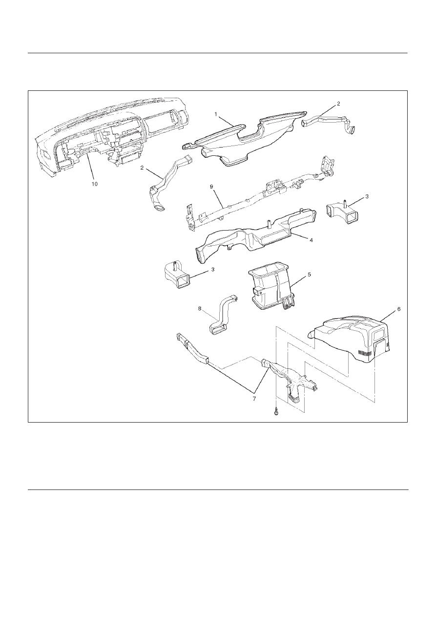
Rear Heater Duct, Defroster Nozzle and Ventilation Duct

Rear Heater Duct, Defroster Nozzle, Ventilation Duct and Associated Parts

874RS017

Legend

(1) Center Defroster Nozzle
(2) Side Defroster Nozzle
(3) Side Ventilation Duct
(4) Center Ventilation Upper Duct
(5) Center Ventilation Lower Duct

(6) Center Console
(7) Rear Heater Duct
(8) Driver Lap Duct
(9) Cross Beam Assembly

(10) Instrument Panel Assembly

Removal

1. Disconnect the battery ground cable.
2. Remove instrument panel assembly.

D

Refer to Instrument Panel Assembly in Body and
Accessories section.

3. Remove center ventilation upper duct.
4. Remove side ventilation duct.
5. Remove center ventilation lower duct.

6. Remove driver lap duct.
7. Remove center console.
8. Remove rear heater duct.

D

Refer to Consoles in Body and Accessories
section.

9. Remove cross beam assembly.

D

Refer to Cross Beam Assembly in Body and
Accessories section.

HEATING, VENTILATION AND AIR CONDITIONING (HVAC) 1A–25

10. Remove side defroster nozzle.

11. Remove center defroster nozzle.

Installation

To install, follow the removal steps in the reverse order,
noting the following point:

1. Connect each duct and nozzle securely leaving no

clearance between them and making no improper
matching.

Center and / or Drive Side Vent

Center Vent, Drive Side Vent and Associated Parts

740RS003

Legend

(1) Center Vent
(2) Meter Cluster Assembly
(3) Lower Cluster Assembly

(4) Front Console Assembly
(5) Instrument Panel Driver Lower Cover

Assembly

(6) Side Vent

Removal

1. Disconnect the battery ground cable.
2. Remove front console assembly.
3. Remove lower cluster assembly.
4. Remove instrument panel driver lower cover

assembly.

5. Remove meter cluster assembly.

D

Refer to Instrument Panel Assembly in Body and
Accessories section.

6. Remove screws and the center vent from center

cluster while prying up the center vent catch portions.

7. Remove screws and the side vent from the center

cluster while prying up the  vent catch portions.

Installation

To install, follow the removal steps in the reverse order.

1A–26 HEATING, VENTILATION AND AIR CONDITIONING (HVAC)

Control Lever Assembly and / or Control Cable

Control Lever Assembly, Control Cable and Associated Parts

865RS011

Legend

(1) Instrument Panel Passenger Lower Cover

Assembly

(2) Glove Box
(3) Fan Switch and Air Conditioning Switch

Connector

(4) Temp Control Link Connection
(5) Control Cable
(6) Blower Assembly Connection

(7) Attaching Screws
(8) Control Lever Assembly
(9) Mode Control Link Connection

(10) Front Console Assembly

(11) Lower Cluster Assembly

(12) Instrument Panel Driver Lower Cover

Assembly

(13) Meter Cluster Assembly

Removal

1. Disconnect the battery ground cable.
2. Remove front console assembly.
3. Remove lower cluster assembly.
4. Remove glove box.

5. Remove instrument panel passenger lower cover

assembly.

6. Remove instrument panel driver lower cover

assembly.

7. Remove meter cluster assembly.

D

Refer to Instrument Panel Assembly in Body and
Accessories section.

HEATING, VENTILATION AND AIR CONDITIONING (HVAC) 1A–27

8. Remove attaching screws.

D

Remove the four attaching screws.

865RS010

9. Pull the control lever assembly out and disconnect the

fan switch and air conditioning switch connectors.

865RS009

10. Remove control lever assembly.

11. Remove control cable.


Content   ..  537  538  539  540   ..