Isuzu Amigo / Axiom / Trooper / Rodeo / VehiCross. Manual - part 449
LIGHTING SYSTEM
8A–17
Starter Switch
Removal and Installation
Refer to
Lock Cylinder in Steering section.
Lighting Switch (Combination Switch)
Removal and Installation
Refer to
Combination Switch in Steering section.
Dimmer·Passing Switch (Combination Switch)
Removal and Installation
Refer to
Combination Switch in Steering section.
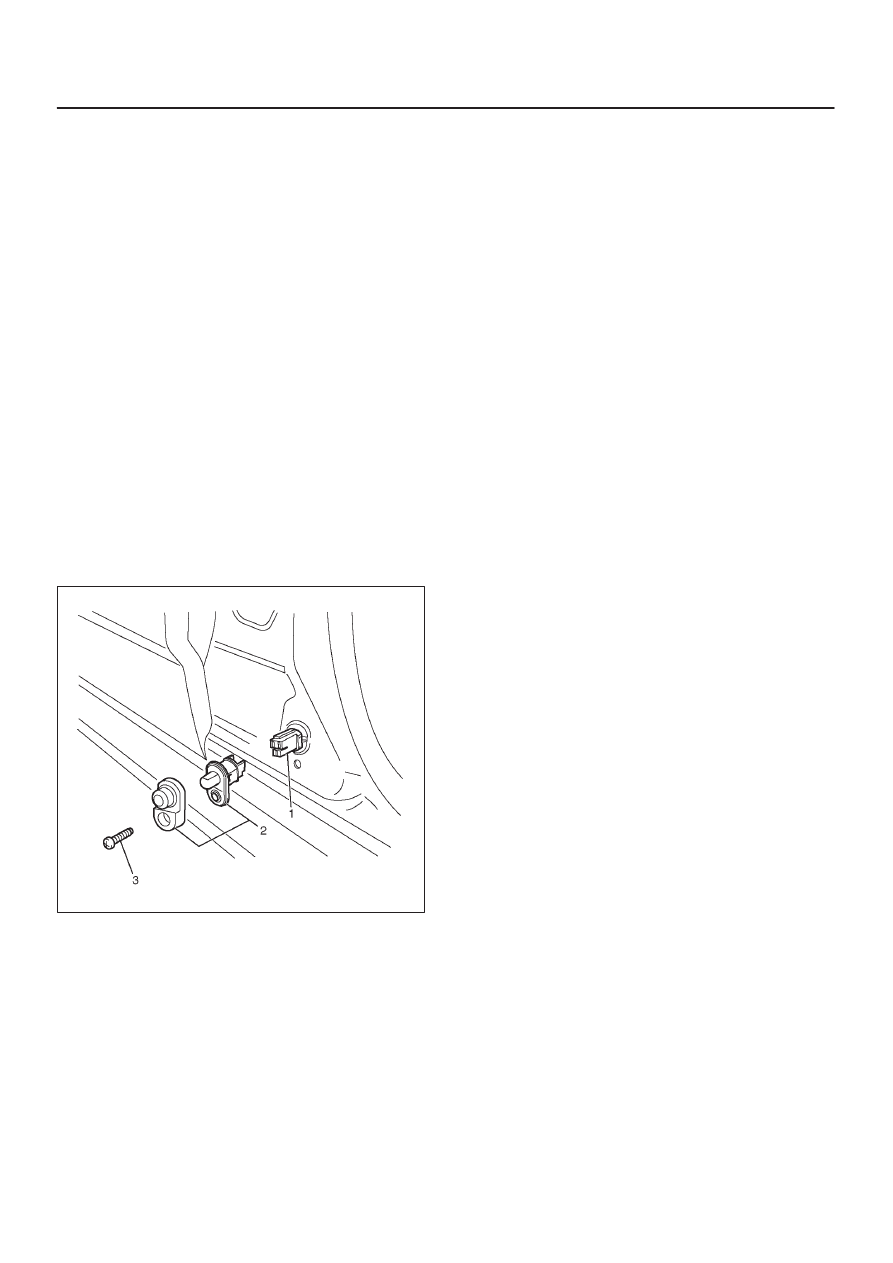
Front Door Switch
Removal
1. Disconnect the battery ground cable.
2. Remove the door switch (2).
D
Remove the screw (3).
D
Disconnect the connector (1).
825R200038
Installation
To install, follow the removal steps in the reverse order.