Isuzu Amigo / Axiom / Trooper / Rodeo / VehiCross. Manual - part 450
LIGHTING SYSTEM
8A–21
Main Data and Specifications
Light and Bulb Specifications
801R200020
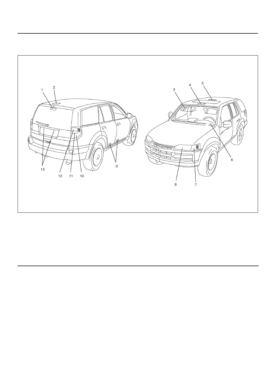
Legend
(1) High Mounted Stoplight
(2) Luggage Room Light
(3) Vanity Mirror Illumination Light
(4) Map Light
(5) Dome Light
(6) Meter
(7) Front Turn Signal Light/Front Side Marker
Light/Parking Light
(8) Headlight
(9) Courtesy Light
(10) Taillight/Stoplight
(11) Backup Light
(12) Rear Turn Signal Light
(13) License Plate Light