Isuzu Amigo / Axiom / Trooper / Rodeo / VehiCross. Manual - part 232


  Index      Isuzu     Isuzu Amigo / Axiom / Trooper / Rodeo / VehiCross - service repair manual 1999-2002 year


Search            


Content   ..  230  231  232  233   ..


Isuzu Amigo / Axiom / Trooper / Rodeo / VehiCross. Manual - part 232


6C–8

ENGINE FUEL (6VE1 3.5L)

Fuel Tube / Quick – Connector Fittings

Precautions

D

Do not light a match or create a flame.

D

Keep flames away from your work area to prevent
flammable materials from catching fire.

D

Disconnect battery ground cable to prevent electrical
shorts.

D

Pre-treat piping system or associated parts from
thermal damage or from spattering when welding or
similar heat-generating work.

Cautions During Work
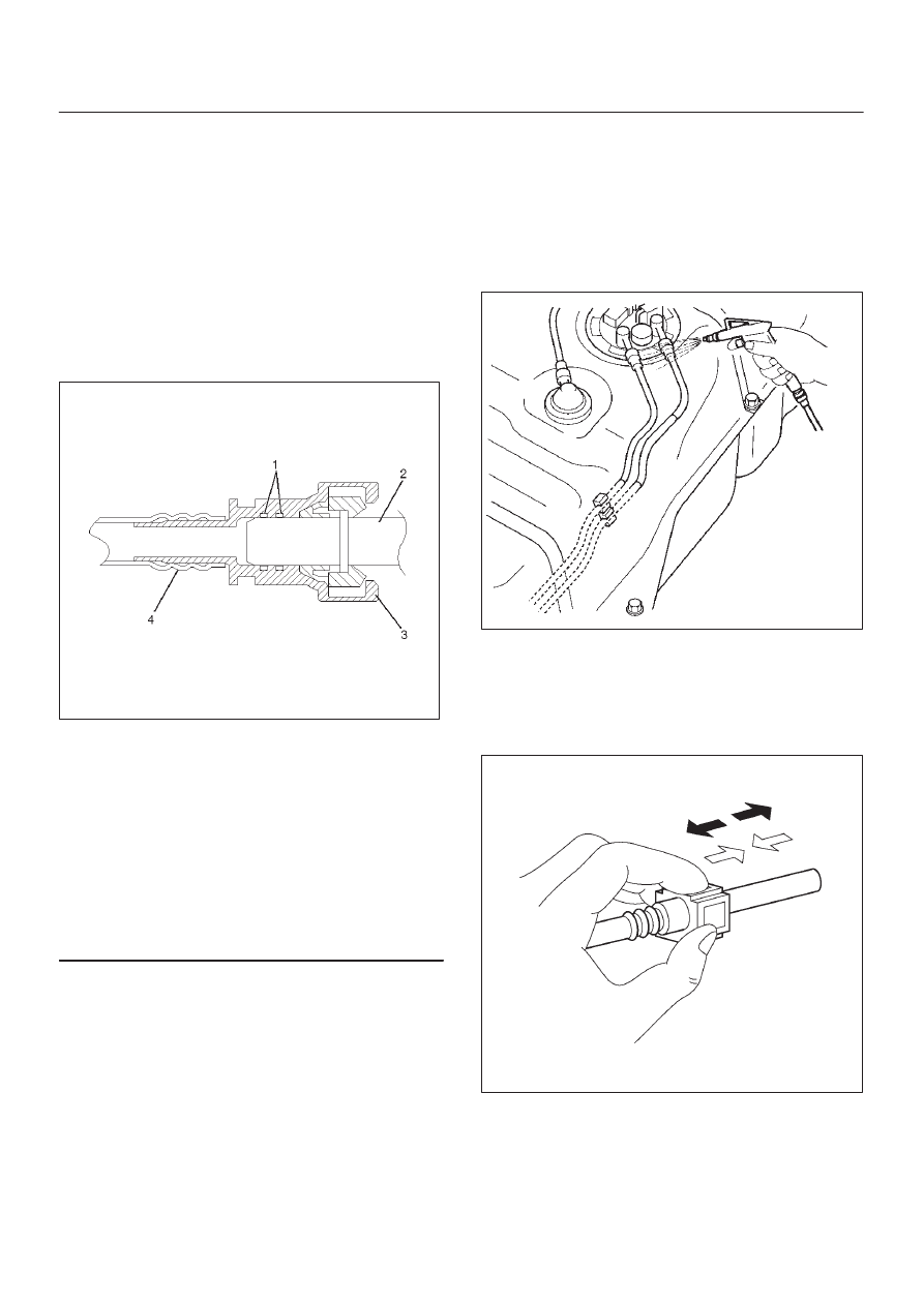
140R100032

Legend

(1) O-ring
(2) Port
(3) Connector
(4) Plastic Tube

NOTE: An O-ring inside the quick connector

provides the seal between the quick
connector and the port. Be careful not to
damage the mating surfaces and O-ring
when attaching the connector. Do not allow
foreign material to enter the connector or the
port.

Do not expose the assembly to battery electrolyte or do
not wipe the assembly with a cloth used to wipe off spilt
battery electrolyte.
Piping that has been splattered with battery electrolyte or
battery electrolyte soaked cloth that was wiped on the
piping cannot be used.

Removal

1. Open the fuel cap to relieve the fuel pressure in the

tank.
Use compressed air to remove any dirt on the fuel
quick connect fittings prior to disconnecting the
fittings.

141R100002

When disconnecting the fuel pipe, cover the area with
a cloth to prevent fuel from splashing as the fuel pipe
may still have some pressure in it.

2. For removal of the quick connector, pull out the

connector with the other hand while pressing the
square relieve button of the connector, as illustrated.

140R200001

6C–9

ENGINE FUEL (6VE1 3.5L)

NOTE: Do not use tools of any kind. Only use bare hands
when disconnecting the connector. Use a lubricant (light
oil) and/or push and pull the connector until the pipe is
disconnected.

Cover the connectors that was removed with a plastic
bag, to prevent dust or rain water from entering.

140R100028

Reuse of Quick–Connector

D

Replace the port and connector if scratch, dent or
crack is found.

D

Remove any dirt build up on the port when installing
the connector. Replace the connector, if there is any
forms of rust, dent, scratch.

D

After cleaning the port, insert it straight into the
connector until it clicks. After it clicks, try pulling it out
to make sure that it is not drawn and is securely
locked.

140R100036

Assembling Advice

By applying engine oil or light oil to the pipe, port makes
pipe assembly easier. The pipe assembly should take
place immediately after applying oil (to prevent dust from
sticking to the pipe surface – which may decrease sealing
ability).
Test/Inspection After Assembling

1. Reconnect the battery negative cable.
2. Turn the ignition key to the “ON” position and listen for

pump start-up sound. Inspect for leaks, the fuel
pressure will increase as the fuel pump is actuated.

3. Perform leak inspection (step 2) several times.
4. Start the engine and observe the engine idle speed.

The presence of dirt in the fuel system may affect the
fuel injection system.

6C–10

ENGINE FUEL (6VE1 3.5L)

Fuel Pump Relay

General Description

In order to control the fuel pump and sender (FPS)
operation, the FPS relay is provided. When the starter
switch is turned to “ON” position, the FPS relay operates
the FPS for 2 seconds.
When the key is turned to “START” position, the Engine
Control Module receives the reference pulse from the
Ignition Control Module and it operates the relay, again
causing the FPS to feed fuel.

Fuel Tank

Fuel Tank and Associated Parts

140R200006

Legend

(1) Fuel Tank Assembly
(2) Fuel Tank Fixing Bolt (QTY: 5)
(3) Fuel Tank Fixing Nut (QTY: 1)
(4) Separator Fixing Bolt (QTY: 2)
(5) Fuel Filler Hose

(6) Fuel Vent Hose
(7) Fuel Feed Hose
(8) Fuel Return Hose
(9) Vapor Pressure Sensor Connector

(10) Fuel Feed Pump Connector

6C–11

ENGINE FUEL (6VE1 3.5L)

Removal

CAUTION: When repair to the fuel system has been
completed, start engine and check the fuel system
for loose connection or leakage. For the fuel system
diagnosis, see Section “Driveability and Emission”.

1. Drain the fuel from the fuel tank, refer to the “Fuel

Pump Flow Test” in this section.

2. Disconnect battery ground cable.
3. Loosen fuel filler cap to reduce the pressure in fuel

tank.

4. Support underneath of the fuel tank assembly (1) with

a lifter.

5. Disconnect fuel feed hose (7) and fuel return hose (8)

near the fuel filter.

NOTE: Plug both ends of the fuel hoses to prevent fuel
leakage.

6. Disconnect fuel filler hose (5) and fuel vent hose (6) at

the fuel filler neck.

NOTE: Cover fuel hoses to prevent any dust entering.

7. Remove two bolts (4) and remove separator.
8. Remove the five fuel tank assembly fixing bolts (2)

and one nut (3).

9. Lower the tank and disconnect the wiring connectors

(9, 10).

Installation

1. Raise the fuel tank assembly (1) and connect the

wiring connectors (9, 10).

2. Install fuel tank assembly along with protectors and

tighten the five fixing bolts (2) and one nut (3) to the
specified torque.

Torque: 68 N·m (50 lb ft)

3. Install the separator and tighten two bolts (4).

Torque: 10 N·m (95 lb in)

4. Connect fuel filler hose (5) and fuel vent hose and clip

them firmly.

5. Connect fuel feed hose (7) and fuel return hose(8),

and clip them firmly.

6. Tighten fuel filler cap until at least three clicks are

heard.

7. Connect battery ground cable.


Content   ..  230  231  232  233   ..