Isuzu Amigo / Axiom / Trooper / Rodeo / VehiCross. Manual - part 233


  Index      Isuzu     Isuzu Amigo / Axiom / Trooper / Rodeo / VehiCross - service repair manual 1999-2002 year


Search            


Content   ..  231  232  233  234   ..


Isuzu Amigo / Axiom / Trooper / Rodeo / VehiCross. Manual - part 233


6C–12

ENGINE FUEL (6VE1 3.5L)

Fuel Gauge Unit

Removal and Installation

Refer to “Fuel Pump” in this section for removal and
installation of the Fuel Gauge Unit, since the fuel gauge
unit is linked to the fuel pump and sender assembly.

Fuel Filler Cap

General Description

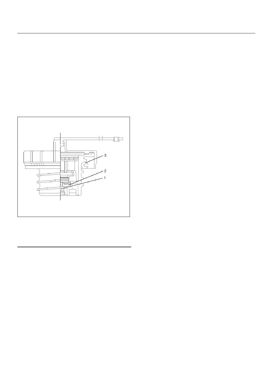
A vacuum valve and pressure valve are built into the fuel
filler cap which adjusts the fuel pressure in the fuel tank to
prevent fuel tank damage.

140R100029

Legend

(1) Vacuum Valve
(2) Pressure Valve
(3) Seal Ring

Inspection

The fuel filler cap must be inspected for seal condition.
The fuel filler cap must be replaced if found defective.

CAUTION:
A replacement fuel filler cap must be the same as the
original. The fuel filler cap valve was designed pri-
marily for this application and must be replaced with
the same type or decreased engine performance may
occur.

6C–13

ENGINE FUEL (6VE1 3.5L)

Main Data and Specifications

Torque Specification

140R200023

Special Tool

ILLUSTRATION

TOOL NO.

TOOL NAME

J–39765

Remover; fuel pump

retainer

ENGINE ELECTRICAL (6VE1 3.5L)

6D1–1

AXIOM

ENGINE

ENGINE ELECTRICAL (6VE1 3.5L)

CONTENTS

Service Precaution

6D1–1

. . . . . . . . . . . . . . . . . . . . . . 

Battery

6D1–2

. . . . . . . . . . . . . . . . . . . . . . . . . . . . . . . . . 

General Description

6D1–2

. . . . . . . . . . . . . . . . . . . . . 

Diagnosis

6D1–2

. . . . . . . . . . . . . . . . . . . . . . . . . . . . . . 

Battery Charging

6D1–3

. . . . . . . . . . . . . . . . . . . . . . 

Jump Starting

6D1–3

. . . . . . . . . . . . . . . . . . . . . . . . . 

Battery Removal

6D1–4

. . . . . . . . . . . . . . . . . . . . . . 

Battery Installation

6D1–4

. . . . . . . . . . . . . . . . . . . . . 

Main Data and Specifications

6D1–5

. . . . . . . . . . . 

Service Precaution

WARNING: THIS VEHICLE HAS A SUPPLEMENTAL
RESTRAINT SYSTEM (SRS).  REFER TO THE SRS
COMPONENT AND WIRING LOCATION VIEW IN
ORDER TO DETERMINE WHETHER YOU ARE
PERFORMING SERVICE ON OR NEAR THE SRS
COMPONENTS OR THE SRS WIRING. WHEN YOU
ARE PERFORMING SERVICE ON OR NEAR THE SRS
COMPONENTS OR THE SRS WIRING, REFER TO
THE SRS SERVICE INFORMATION. FAILURE TO
FOLLOW WARNINGS COULD RESULT IN POSSIBLE
AIR BAG DEPLOYMENT, PERSONAL INJURY, OR
OTHERWISE UNNEEDED SRS SYSTEM REPAIRS.

CAUTION: Always use the correct fastener in the
proper location. When you replace a fastener, use
ONLY the exact part number for that application.
ISUZU will call out those fasteners that require a
replacement after removal. ISUZU will also call out
the fasteners that require thread lockers or thread
sealant. UNLESS OTHERWISE SPECIFIED, do not
use supplemental coatings (Paints, greases, or other
corrosion inhibitors) on threaded fasteners or
fastener joint interfaces. Generally, such coatings
adversely affect the fastener torque and the joint
clamping force, and may damage the fastener. When
you install fasteners, use the correct tightening
sequence and specifications. Following these
instructions can help you avoid damage to parts and
systems.

SECTION

6D1–2

ENGINE ELECTRICAL (6VE1 3.5L)

Battery

General Description

The battery is completely sealed except for the two small
vent holes (2) on the side. These vent holes (2) permit the
escape of small amounts of gas generated by the battery.
This type of battery has the following advantages over
conventional batteries:

1. There is no need to add water during the entire

service life of the battery.

2. The battery is much less vulnerable to self discharge

than a conventional type battery.

Diagnosis

1. Visual Inspection

Inspect the battery for obvious physical damage, such as
a cracked or broken case, which would permit electrolyte
loss.
Replace the battery if obvious physical damage is
discovered during inspection.
Check for any other physical damage and correct it as
necessary.

2. Hydrometer Check

There is a built–in hydrometer (Charge test indicator(1))
at the top of the battery. It is designed to be used during
diagnostic procedures.
Before trying to read the hydrometer, carefully clean the
upper battery surface.
If your work area is poorly lit, additional light may be
necessary to read the hydrometer.

a. BLUE RING OR DOT VISIBLE(4) – Go to Step 3. 
b. BLUE RING OR DOT NOT VISIBLE(3) – Replace

the battery. 

061R200001

3. Voltage Check

1. Put voltmeter test leads to battery terminals.

a. VOLTAGE IS 12.4V OR ABOVE – Go to Step 4

Load Test. 

b. VOLTAGE IS UNDER 12.4V – Go to procedure (2)

below. 

2. Determine fast charge amperage from specification.

(See Main Data and Specifications in this section). 
Fast charge battery for 30 minutes at amperage rate
no higher than specified value.
Take voltage and amperage readings after charge.

a. VOLTAGE IS ABOVE 16V AT BELOW 1/3 OF

AMPERAGE RATE – Replace battery.

b. VOLTAGE IS ABOVE 16V AT ABOVE 1/3 OF

AMPERAGE RATE – Drop charging voltage to 15V
and charge for 10 – 15 hours. Then go to Step 4
Load Test.

c. VOLTAGE IS BETWEEN 12V AND 16V –

Continue charging at the same rate for an
additional 3–1/2 hours. Then go to Step 4 Load
Test.

d. VOLTAGE BELOW 12V – Replace the Battery.

4. Load Test

1. Connect a voltmeter and a battery load tester across

the battery terminals.

2. Apply 300 ampere load for 15 seconds to remove

surface charge from the battery. Remove load.

3. Wait 15 seconds to let battery recover. Then apply

specified load from specifications (See Main Data
and Specifications in this section).
Read voltage after 15 seconds, then remove load.

a. VOLTAGE DOES NOT DROP BELOW THE

MINIMUM LISTED IN THE TABLE – The battery is
good and should be returned to service.

b. VOLTAGE IS LESS THAN MINIMUM LISTED –

Replace the battery.

ESTIMATED TEMPERATURE

MINIMUM

VOLTAGE

°

F

°

C

V

70

21

9.6

60

16

9.5

50

10

9.4

40

4

9.3

30

–1

9.1

20

–7

8.9

10

–12

8.7

0

–18

8.5

The battery temperature must be estimated by feel

and by the temperature the battery has been

exposed to for the preceding few hours.


Content   ..  231  232  233  234   ..