Isuzu Amigo / Axiom / Trooper / Rodeo / VehiCross. Manual - part 231


  Index      Isuzu     Isuzu Amigo / Axiom / Trooper / Rodeo / VehiCross - service repair manual 1999-2002 year


Search            


Content   ..  229  230  231  232   ..


Isuzu Amigo / Axiom / Trooper / Rodeo / VehiCross. Manual - part 231


6C–4

ENGINE FUEL (6VE1 3.5L)

Fuel Filter

Removal

CAUTION: When repair to the fuel system has been
completed, start engine and check the fuel system
for loose connection or leakage. For the fuel system
diagnosis, see Section “Driveability and Emission”.

1. Disconnect battery ground cable.
2. Remove Fuel filler cap(1).

140R100023

Legend

(1) Fuel Filler Cap
(2) Receive Rubber Drain

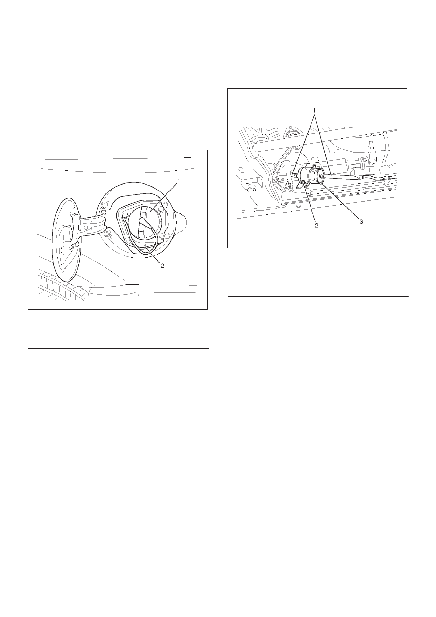
3. Disconnect fuel hoses(1) from fuel filter on both

engine side and fuel tank side.

4. Fuel filter fixing bolt(2).

D

Remove the fuel filter fixing bolt(2) on fuel filter
holder.

5. Remove fuel filter(3).

041RW003

Legend

(1) Fuel Hose
(2) Fuel Filter Fixing Bolt
(3) Fuel Filter

Inspection

1. Replace the fuel filter if the fuel leaks from fuel filter

body or if the fuel filter body itself is damaged.

2. Replace the filter if it is clogged with dirt or sediment.
3. Check clogged drain port of the receive rubber by the

foreign material, repair or clear if found clog it.

6C–5

ENGINE FUEL (6VE1 3.5L)

Installation

1. Install the fuel filter in the proper direction.
2. Install fuel filter holder fixing bolt.
3. Connect fuel hoses on engine side(1) and fuel tank

side(2).

041RW001

4. Install fuel filler cap
5. Connect the battery ground cable.

Inspection

After installation, start engine and check for fuel leakage.

In–Tank Fuel Filter

The filter is located on the lower end of fuel pickup tube in
the fuel tank. The fuel filter prevents dirt and water the fuel
system not unless the filter is submerged in water. The
fuel filter is maintenance free, that requires no
maintenance. Excess water and sediment in the tank
restricts fuel supply to the engine, resulting in engine stall.
If this happens, the fuel tank would need to be cleaned
thoroughly.

Fuel Pump Flow Test

If reduction of fuel supply is suspected, perform the
following checks.

1. Make sure that there is fuel in the tank.
2. With the engine running, check the fuel feed pipe and

hose from fuel tank to injector for evidence of
leakage. Retighten, if pipe or hose connection is
loose. Also, inspect bent or kink fuel pipes and hoses.

3. Insert the hose from fuel feed pipe into a clean

container, and check for fuel pump flow rate.

4. Connect the pump relay terminals with a jumper

wire(1) as shown and start the fuel pump to measure
delivery.

140R200003

CAUTION: Never generate sparks when connecting
a jumper wire.

Delivery Times

Delivery

15 seconds

0.38 liters minimum

If the measure value is out of standard, conduct the
pressure test.

Pressure test

For the pressure test to the fuel system, see Section 6E
“Fuel Control System”.

6C–6

ENGINE FUEL (6VE1 3.5L)

Fuel Pump

Fuel Pump and Associated Parts

140R200008

Legend

(1) Fuel Feed Port
(2) Fuel Tube/Quick Connector
(3) Fuel Return Port
(4) Fuel Pump and Sender (FPS) Assembly

(5) Connector; Fuel Feed Pump
(6) Connector; Fuel Tank Pressure Sensor
(7) Retainer (Fuel Pump Lock)
(8) Fuel Tank Assembly
(9) Seal; Fuel Pump

Removal

CAUTION: When repair to the fuel system has been
completed, start engine and check the fuel system
for loose connection or leakage. For the fuel system
diagnosis, see Section “Driveability and Emission”.

1. Remove fuel tank assembly(8). Refer to “Fuel Tank

Removal” in this section.

2. Remove Fuel Tube/Quick Connector (2).

NOTE: Refer to “Fuel Tube/Quick Connector Fittings” in
this section when performing any repairs.

6C–7

ENGINE FUEL (6VE1 3.5L)

3. Remove the retainer (7) with tool J–39765 and

remove the fuel pump and sender (FPS) assembly
(4).

140R200007

NOTE: After removing pump assembly (4), cover fuel
tank to prevent any dust entering.

Installation

1. Install FPS assembly(4) with retainer (7) and new

seal; fuel pump (9) by J–39765.

2. Install Fuel Tube/Quick Connector (2).

NOTE: Refer to “Fuel Tube/Quick Connector Fittings” in
this section when performing any repairs.

3. Install fuel tank assembly(8). Refer to “Fuel Tank

Installation”.


Content   ..  229  230  231  232   ..