Isuzu Amigo / Axiom / Trooper / Rodeo / VehiCross. Manual - part 230
ENGINE COOLING (6VE1 3.5L)
6B–13
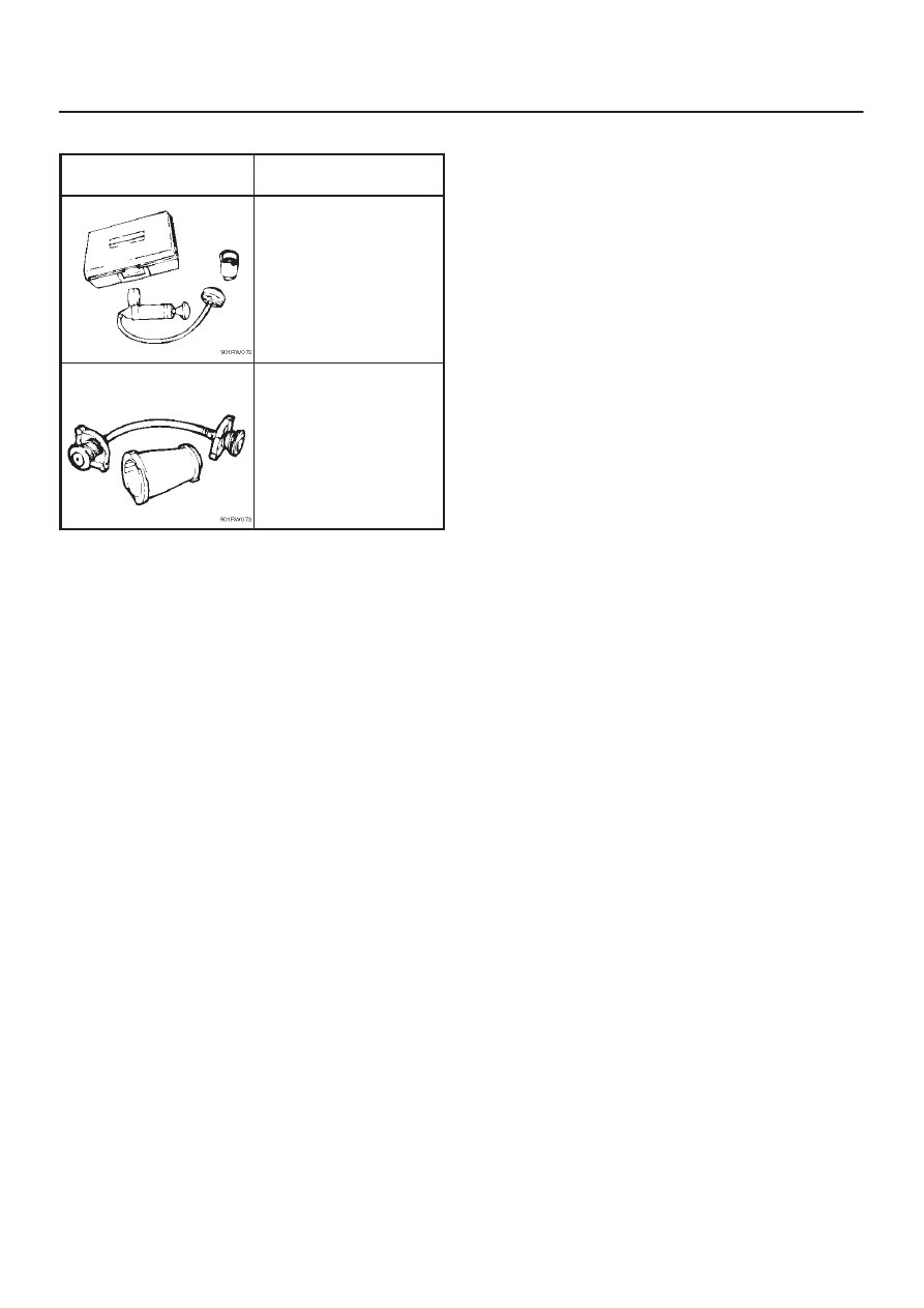
Special Tool
ILLUSTRATION
TOOL NO.
TOOL NAME
J–24460–01
Tester; radiator cap
J–33984–A
Adapter; radiator cap
Index Isuzu Isuzu Amigo / Axiom / Trooper / Rodeo / VehiCross - service repair manual 1999-2002 year
|
|
|
ENGINE COOLING (6VE1 3.5L) 6B–13 Special Tool ILLUSTRATION TOOL NO. TOOL NAME J–24460–01 Tester; radiator cap J–33984–A Adapter; radiator cap |