Content .. 1665 1666 1667 1668 ..
Isuzu Amigo / Axiom / Trooper / Rodeo / VehiCross. Manual - part 1667
8H–14
SECURITY AND LOCKS
Power Door Lock System
General Description
The circuit consists of the door lock (& power window)
switch, door lock actuator for the front and rear door,
tailgate lock actuator and the door lock key switch.
The front door lock switch–LH is always provided with
the battery voltage.
The key or the inside lock button on both driver's and
front passenger's door can activate the lock mechanism
of all the doors (including the tailgate).
When the driver's door lock switch or the front
passenger's door lock switch is turned on, current flows
for about one second to the door lock actuator of each
door connected in parallel with the front door lock (&
power window) switch–LH to activate the actuator to
lock and unlock the doors.
Door Lock Key Switch
Removal and Installation
• Refer to the Front Door Lock Assembly removal and
installation steps in this section.
Front Door Lock Actuator
Removal and Installation
• Refer to the Front Door Lock Assembly removal and
installation steps in this section.
Rear Door Lock Actuator
Removal and Installation
• Refer to the Rear Door Lock Assembly removal and
installation steps in this section.
Tailgate Lock Actuator
Removal and Installation
• Refer to the Tailgate Lock Assembly removal and
installation steps in this section.
Anti-Theft System
General Description
The circuit consists of the starter switch, anti–theft &
keyless entry controller, anti–theft horn, front door and
tailgate key switch (detect and tamper) switch, door lock
actuator for each door, engine hood switch, clutch start
switch (M/T), ANTI–THEFT indicator light and mode
switch (A/T).
The system operates as follows: After locking the starter
switch and removing the starter key (this sets the
alarm), if the door is unlocked in any way other than with
the proper key, the headlights will start flashing, the horn
sounds, and the starter circuit is disabled. (However, the
engine hood and all the doors must be locked and
closed.)
Once the system has been placed in the warning or
alarm condition, it can be released only when the starter
switch is shifted from “OFF" to “ACC" by the starter key,
or when the lock of the front door or the tailgate is
released (to activate the detect switch) by the starter
key.
Anti–Theft & Keyless Entry
Controller
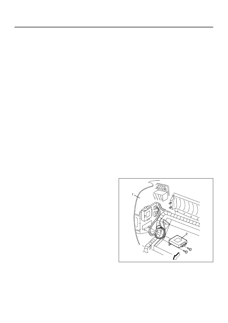
Removal
1. Disconnect the battery ground cable.
2. Remove the glove box fram the instrument panel
assembly (1).
• Refer to the Instrument Panel Assembly in Body
Structure section.
3. Remove the anti–theft & keyless entry controller (2).
• Disconnect the connector.
• Remove two fixing screws.
826R200024
Installation
To install, follow the removal steps in the reverse order.