Isuzu Amigo / Axiom / Trooper / Rodeo / VehiCross. Manual - part 1666


  Index      Isuzu     Isuzu Amigo / Axiom / Trooper / Rodeo / VehiCross - service repair manual 1999-2002 year


Search            


Content   ..  1664  1665  1666  1667   ..


Isuzu Amigo / Axiom / Trooper / Rodeo / VehiCross. Manual - part 1666


8H–10

SECURITY AND LOCKS

3. Remove the waterproof sheet.

• Remove the waterproof sheet, taking special care

so as not to break it.

4. Remove the hatchgate lock.

• Disconnect the lock link and connector and

remove the 3 fixing bolts.

5. Remove the key cylinder.

• Disconnect the lock links.

• Remove the key cylinder retaining clip with screw

driver to remove the key cylinder.

683RW002

6. Remove the hatchgate lock actuator assembly.

• Disconnect the actuator harness connector.

• Remove the 2 bolts holding hatchgate lock

actuator assembly from inside.

7. Remove the outside handle.

• Remove the 2 bolts holding the outside handle

from inside.

8. Remove the tailgate lock assembly.

• Remove the 3 screws holding the lock assembly.

Installation

To install, follow the removal steps in the reverse order,
noting the following points:

1. When setting up links, pay attention to the position

and direction of the links.

683RW003

EndOFCallout

2. Apply chassis grease to the lock assembly and

striker moving surface.

3. Check that the tailgate lock operates correctly after

installing it.

4. Tighten the tailgate lock assembly fixing bolts to the

specified torque.

Torque 7 N·m (61 Ib in)

5. Tighten the hatchgate lock assembly fixing bolts to

the specified torque.

Torque 9 N·m (78 Ib in)
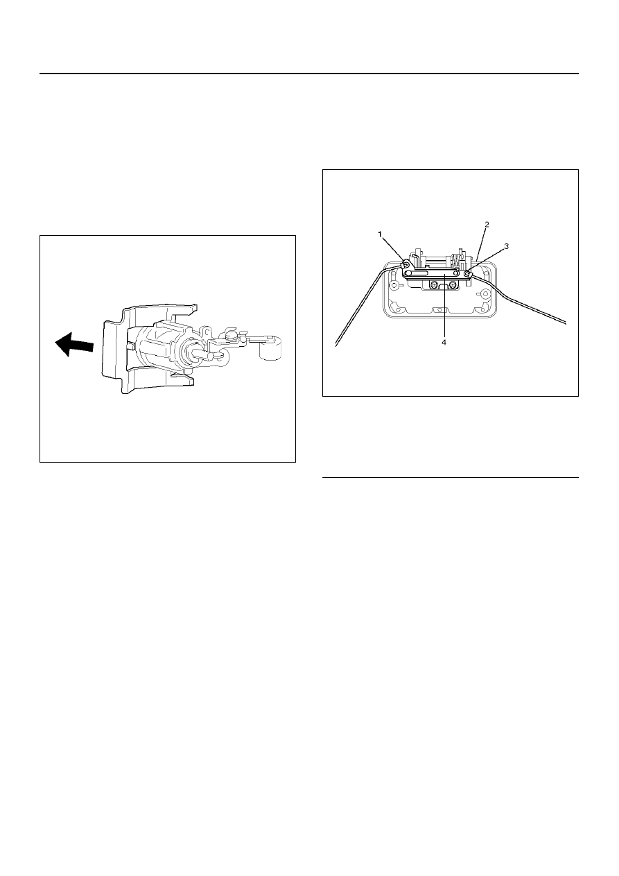
Legend

(1) Tailgate Lock Link
(2) Outside Handle
(3) Key Cylinder Link
(4) Cancel Mechanism

SECURITY AND LOCKS

8H–11

Tailgate Lock (SWB)

Tailgate Lock and Associated Parts

681RY00001

EndOFCallout

Removal

1. Disconnect the battery ground cable.

2. Remove the tailgate glass assembly and tailgate

glass stay.

• Refer to Tailgate Glass (SWB) in Body Structure

section.

3. Remove the tailgate trim cover assembly.

• Remove the two screws fixing the trim cover

assembly and pull up the trim cover after
detaching the clips from tailgate panel.

4. Remove the waterproof sheet.

• Remove the waterproof sheet, taking special care

so as not to break it.

5. Remove the key cylinder.

• Disconnect the lock links.

• Remove the key cylinder retaining clip with screw

driver to remove the key cylinder.

6. Remove the hatchgate lock actuator assembly.

• Disconnect the actuator harness connector.

• Remove the two nuts holding hatchgate lock

actuator assembly from inside.

7. Remove the outside handle.

• Disconnect the lock link.

• Remove the two bolts holding the outside handle

from inside.

8. Remove the tailgate lock assembly.

• Remove the three screws holding the lock

assembly.

Legend

(1) Tailgate Assembly
(2) Waterproof sheet
(3) Trim Cover Assembly

(4) Key Cylinder
(5) Tailgate Lock Assembly
(6) Outside Handle
(7) Hatchgate Lock Actuator Assembly

8H–12

SECURITY AND LOCKS

Installation

To install, follow the removal steps in the reverse order,
noting the following points:

1. Apply chassis grease to the lock assembly and

striker moving surface.

2. Tighten the tailgate lock assembly fixing screws to

the specified torque.

Torque 7 N·m (61 lb in)

3. Check that the tailgate lock operates correctly after

installing it.

SECURITY AND LOCKS

8H–13

Key

Key Coding

730RX001

EndOFCallout

One key is used for the ignition, door, and tailgate lock
cylinders. The keys are cut on both edges to make them
reversible.
Key identification is obtained from the five character key
code stamped on the key code tag. From this key code,
the key code cutting combination can be determined
from a code list (available to owners of key cutting
equipment from suppliers).
If key codes are not available from records or tags, the
key code can be obtained from the right hand door lock
cylinder (if lock has not been replaced). Lock cylinders
supplied by the factory as service parts are unmarked.
If the original key is available, the key code cutting
combination can be determined by laying the key on the
diagram shown in the figure.

Key Styles

730RX002

EndOFCallout

The keys come in styles A or B depending on the key
code cutting combination. When the first position in the
combination is a 1, 2 or 3, Style A is used. When the first
position is a 4, Style B (factory pre-cut key) is used.

Legend

(1) Key (Actual size)
(2) Key Code Tag

(3) Position
(4) Level

Legend

(1) Blank Key Style “A"
(2) Blank Key Style “B"


Content   ..  1664  1665  1666  1667   ..