Isuzu Amigo / Axiom / Trooper / Rodeo / VehiCross. Manual - part 1664


  Index      Isuzu     Isuzu Amigo / Axiom / Trooper / Rodeo / VehiCross - service repair manual 1999-2002 year


Search            


Content   ..  1662  1663  1664  1665   ..


Isuzu Amigo / Axiom / Trooper / Rodeo / VehiCross. Manual - part 1664


8H–2

SECURITY AND LOCKS

Front Door Lock Assembly

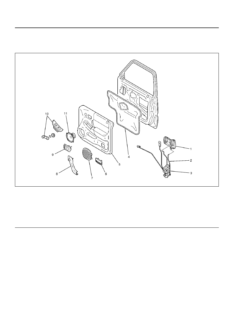
Front Door Lock Assembly and Associated Parts

635RY00003

EndOFCallout

Legend

(1) Outside Handle
(2) Door Locking Link
(3) Door Lock Assembly
(4) Waterproof Sheet
(5) Door Trim Panel
(6) Courtesy Light Lens

(7) Speaker Grille
(8) Grip Cover
(9) Inside Handle

(10) Power Window Switch/Window Regulator 

Handle

(11) Speaker Assembly

SECURITY AND LOCKS

8H–3

Removal

1. Disconnect the battery ground cable.

2. Remove the power window switch (1)/regulator

handle.

• Pry out the power window switch and remove the

connectors.

635RW004

• To remove the regulator handle (1), remove the

clip (2), at the root of the handle by using wire
with hook.

631RW004

3. Remove the screw while pulling the inside lever

toward you and then remove the inside handle.

632RW003

4. Remove the speaker grille (1).

• Pull out the front side of the grille.

5. Remove the speaker assembly (2).

• Remove 4 screws and disconnect the speaker

harness connector (3).

890RX012

8H–4

SECURITY AND LOCKS

6. Remove the courtesy light lens.

7. Remove the 5 screws (1), (3) and pull out the door

trim panel at the 6 clip (2) positions.

635RW007

8. Remove the waterproof sheet.

• Taking notice of the door harness, peel the

waterproof sheet off the door panel carefully.

9. Raise the glass up to the uppermost position, and

then remove the rear guide rail.

10. Disconnect the locking links then remove the door

lock assembly fixing screws and door lock
assembly.

632RY00005

Installation

To install, follow the removal steps in the reverse order,
noting the following points:

1. Apply chassis grease to the lock assembly and

striker moving surface.

2. Install the regulator handle as shown in the

illustration, if equipped without power windows.

631RW005

3. Tighten the door lock assembly fixing screws to the

specified torque.

Torque 7 N·m (61 Ib in)

4. Check that the door lock operates smoothly.

SECURITY AND LOCKS

8H–5

Front Outside Handle

Front Outside Handle and Associated Parts

635RY00003

EndOFCallout

Removal

1. Disconnect the battery ground cable.

2. Remove the door trim panel.

• Refer to Front Door Lock Assembly in this

section.

3. Remove the waterproof sheet.

• Taking notice of the door harness, peel the

waterproof sheet off the door panel carefully.

4. Disconnect the locking links and remove the outside

handle.

5. Remove the fixing clip to remove the door lock

cylinder.

Installation

To install, follow the removal steps in the reverse order,
noting the following points:

1. Be sure to install the door lock cylinder at a right

angle to the outside handle.

2. Check for smooth outside handle and lock cylinder

operation.

3. Tighten the outside handle fixing bolts to the

specified torque.

Torque 9 N·m (78 Ib in)

Legend

(1) Outside Handle
(2) Door Locking Link
(3) Door Lock Assembly
(4) Waterproof Sheet
(5) Door Trim Panel
(6) Courtesy Light Lens

(7) Speaker Grille
(8) Grip Cover
(9) Inside Handle

(10) Power Window Switch/Window Regulator 

Handle

(11) Speaker Assembly


Content   ..  1662  1663  1664  1665   ..