Isuzu Amigo / Axiom / Trooper / Rodeo / VehiCross. Manual - part 1549


  Index      Isuzu     Isuzu Amigo / Axiom / Trooper / Rodeo / VehiCross - service repair manual 1999-2002 year


Search            


Content   ..  1547  1548  1549  1550   ..


Isuzu Amigo / Axiom / Trooper / Rodeo / VehiCross. Manual - part 1549


7A–36

AUTOMATIC TRANSMISSION (4L30–E)

Shift Lock Cable

Removal

1. Set ignition key in “LOCK” position and selector lever

in “P” position.

2. Remove transfer control lever knob (4

×

4), lower

cluster assembly, rear console, center console,
selector lever knob and cover.

D

Refer to Selector Lever in this section.

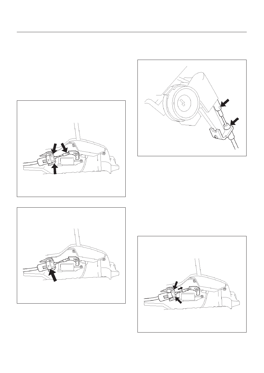
3. Disconnect inner cable from selector lever assembly

then push claw and disconnect cable assembly.

256RW016

4. Disconnect lock adjust.

256RW017

5. Remove instrument panel lower cover and steering

column cover.

6. Remove spring pin and disconnect inner cable.

D

Disconnect outer cable from bracket.

256RW008

Installation

1. Set ignition key in “LOCK” position and selector lever

in “P” position.

2. Connect outer cable to bracket near steering lock.

D

Connect inner cable to steering lock and install
spring pin.

3. Install steering column cover and instrument lower

cover.

4. Install adjust body of cable assembly to bracket in

selector lever assembly.

D

Install inner cable to lever, pulling inner cable with
outer cable.

256RW018

7A–37

AUTOMATIC TRANSMISSION (4L30–E)

5. Check that cable moves smoothly, lightly pulling outer

cable rearward.

256R100001

6. Connect lock adjust, aligning “T” mark in the “Up”

position.

256RW017

7. About following installation steps, refer to 

Selector

Lever in this section.

8. Check the shift lock operation:

a. Selector lever should not be moved out of “P”

position with ignition key in “Lock” position.

b. Selector lever can be moved out of “P” position with

ignition key in “ON”position only when brake pedal
is depressed.

c. ignition key can be turned to “LOCK” position only

when selector lever is in “P” position (key can be
pulled out).

9. If a. and c. fail, readjust cable. If b. fails, readjust

connector wiring and brake pedal switch.

Mode Switch

Removal

1. Place selector lever in neutral.
2. Disconnect battery ground cable.
3. Remove mode switch cover (1) (V6).
4. Disconnect selector lever (2) from the mode switch.
5. Remove bracket with cable (3).
6. Disconnect transmission harness from the mode

switch connector (4).

7. Remove bracket with mode switch connector from

the transmission case.

8. Remove mode switch connector (4) from the bracket

(5).

9. Remove two mode switch bolts and nut then remove

mode switch (6).

(V6)

210RW014

7A–38

AUTOMATIC TRANSMISSION (4L30–E)

Installation

To install, follow the removal steps in the reverse order,
noting the following points;

1. Torque

Mode switch bolt: 13 N

m (113 lb in)

Selector lever nut: 23 N

m (17 lb ft)

2. Mode switch setting procedure

Perform either of the following adjustment
procedures:

Procedure 1

a. Place selector lever in neutral.
b. Remove selector lever from the mode switch.
c. Remove the mode switch cover.
d. Loosen the two 10 mm screws.
e. Rotate the mode switch until the slot in the mode

switch housing aligns with the selector shaft
bushing, and insert a 3/32 in. (2.4 mm) drill bit or
punch (1) into the slot.

f. Tighten the screws to 13 N·m (113 lb in).
g. After completing adjustment, snap the mode

switch cover into place.

h. Reinstall the selector lever.

249RW001

Procedure 2

a. Place selector lever in neutral.
b. Disconnect transmission harness connector from

mode switch connector.

c. Remove mode switch connector with bracket from

the transmission case.

d. Connect multimeter (resistance mode) to

terminals 1(E) and 4(H) on mode switch connector.

e. Loosen two mounting screws.
f. Rotate mode switch slightly in both directions to

determine the range (approx. 5 degrees) of
electrical contact.

g. Position mode switch in middle of contact range.
h. Tighten two mounting screws.

i. Remove multimeter and install mode switch

harness connector with bracket to the
transmission case.

j. Connect transmission harness connector to mode

switch connector.

F07RW003

7A–39

AUTOMATIC TRANSMISSION (4L30–E)

Transmission Assembly

Transmission and Associated Parts

(V6 Model)

240RY00041

Legend

(1) Transfer Protector (4

×

4)

(2) Fairing Plate
(3) Rear Propeller Shaft
(4) Front Propeller Shaft (4

×

4)

(5) Center Exhaust Pipe (4

×

4)

(6) Fuel Pipe Heat Protector
(7) Harness Heat Protector
(8) Rear Mount Nut
(9) Third Crossmember

(10) Transmission Oil Cooler Pipe

(11) Starter

(12) Under Cover
(13) Transfer Control Lever (4

×

4)

(14) Select Cable
(15) Torque Converter Bolt
(16) Engine-Transmission Bolt
(17) Transmission Assembly
(18) Rear Mount Rubber and Propeller Protector

Assembly (4

×

2)


Content   ..  1547  1548  1549  1550   ..