Isuzu Amigo / Axiom / Trooper / Rodeo / VehiCross. Manual - part 1547


  Index      Isuzu     Isuzu Amigo / Axiom / Trooper / Rodeo / VehiCross - service repair manual 1999-2002 year


Search            


Content   ..  1545  1546  1547  1548   ..


Isuzu Amigo / Axiom / Trooper / Rodeo / VehiCross. Manual - part 1547


7A–28

AUTOMATIC TRANSMISSION (4L30–E)

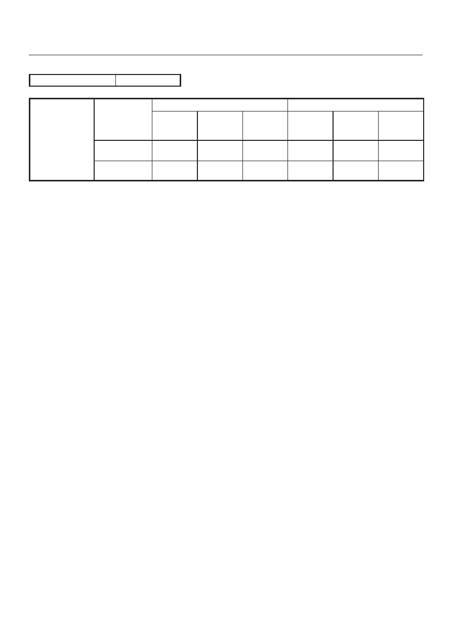
Lockup Speed Chart (HEC)

Rear axle ratio

4.777

Lockup ON

Lockup OFF

D range,

Throttle opening

Mode

2nd

km/h

(mph)

3rd

km/h

(mph)

4th

km/h

(mph)

2nd

km/h

(mph)

3rd

km/h

(mph)

4th

km/h

(mph)

Throttle o ening

6%

Normal

77 

 83

(48 

 52)

77 

 83

(48 

 52)

77 

 83

(48 

 52)

72 

 78

(45 

 48)

41 

 47

(25 

 29)

61 

 67

(38 

 42)

Power

66 

 72

(41 

 45)

70 

 76

(44 

 47)

70 

 76

(44 

 47)

61 

 67

(38 

 42)

62 

 68

(38 

 42)

66 

 72

(41 

 31)

7A–29

AUTOMATIC TRANSMISSION (4L30–E)

Changing Transmission Fluid

There is no need to change the transmission fluid unless
the transmission is used under one or more of the
following heavy duty conditions.
A. Repeated short trips
B. Driving on rough roads
C. Driving on dusty roads
D. Towing a trailer
If the vehicle is used under these conditions, change the
fluid every 20,000 miles (32,000 km).

1. Place a large drain pan under the oil pan.
2. Remove the transmission oil drain screw (2) and drain

fluid.

3. Tighten drain screw (2).

Torque: 38 N

m (28 lb ft)

4. Remove the transmission overfill screw (1) and fill

transmission through overfill screw opening, using
DEXRON

–III ATF.

NOTE: Add transmission fluid until it flows out over the
overfill screw opening.

5. Let engine idle until a fluid temperature between 32

°

C

(90

°

F) and 57

°

C (135

°

F) is reached.

6. Add transmission fluid until it flows out over the overfill

screw opening, then close the overfill screw (1).

Torque: 38 N

m (28 lb ft)

NOTE: To prevent fluid leaks, the overfill screw and oil
drain screws gasket must be replaced each time these
screws are removed.

NOTE: Check transmission fluid temperature with scan
tool.

7. Reset “Oil Life Monitor” data by using Tech 2.

Refer to Tech 2 OBD II Connection in Transmission
Control System (4L30-E) section.

242RW003

Selector Lever

Inspection

1. Make sure that when the selector lever is shifted from

“P” to “L”, a “clicking” can be felt at each shift position.
Make sure that the gear corresponds to that of the
position plate indicator.

2. Check to see if the selector lever can be shifted as

shown in illustration.

C07RW009

Removal

1. Disconnect battery ground cable.
2. Set ignition Key in “LOCK” position and selector lever

in ”P” position.

3. Remove transfer control lever knob (4

×

4). 

4. Remove lower cluster assembly.

740RW021

7A–30

AUTOMATIC TRANSMISSION (4L30–E)

5. Remove rear console.

256RW005

6. Remove center console.

(4

×

4)

256RW006

(4

×

2)

745R100001

7. Remove selector lever knob and cover.

256RW020

8. Disconnect select cable.

D

Refer to Select Cable in this section.

9. Disconnect shift lock cable.

D

Refer to Shift Lock Cable in this section.

10. Disconnect harness connector.

7A–31

AUTOMATIC TRANSMISSION (4L30–E)

11. Remove selector lever subassembly.

256RX001

Installation

1. Install selector lever subassembly.
2. Connect harness connector.
3. Connect shift lock cable.

D

Refer to Shift Lock Cable in this section.

4. Connect select cable.

D

Refer to Select Cable in this section.

5. Install selector lever knob and cover.

256RX002

6. Install center console.
7. Install rear console.
8. Install lower cluster assembly.
9. Install transfer control lever knob (4

×

4).

10. Connect negative (–) battery cable.

11. After installation, make sure that the selector lever

operates normally, and that each selector position is
properly indicated. (The red mark shows through the
window.)

Select Cable

Removal

1. Set selector lever in “P” position.
2. Remove transfer control lever knob, lower cluster

assembly, rear console, center console, selector
lever knob and cover.

D

Refer to Selector Lever in this section.

3. Disconnect inner cable by pulling projection on pin.

(4

×

4)

256RW022


Content   ..  1545  1546  1547  1548   ..