Isuzu Amigo / Axiom / Trooper / Rodeo / VehiCross. Manual - part 46


  Index      Isuzu     Isuzu Amigo / Axiom / Trooper / Rodeo / VehiCross - service repair manual 1999-2002 year


Search            


Content   ..  44  45  46  47   ..


Isuzu Amigo / Axiom / Trooper / Rodeo / VehiCross. Manual - part 46


2A–30 POWER–ASSISTED STEERING SYSTEM
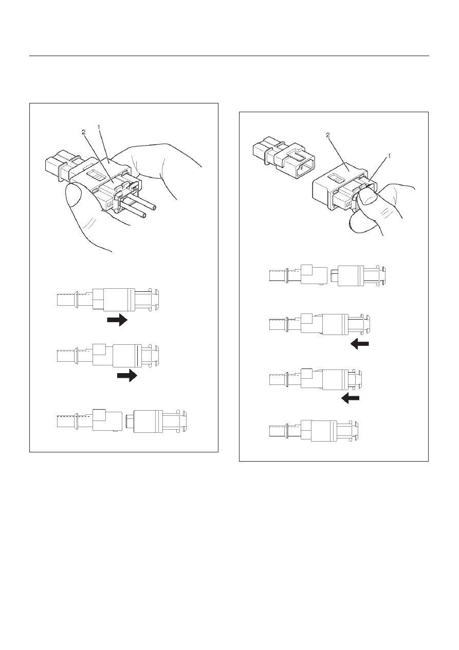
Removal

To remove the connector, hold the cover insulator(1) and
pull it. The cover insulator slides and lock will be released.
Do not hold the socket insulator(2).

827RW028

Installation

To install the connector, hold the soket insulator(1) and
insert it. The cover insulator slides and connector will be
locked.
Do not hold the cover insulator(2).

827RW027

POWER–ASSISTED STEERING SYSTEM

2A–31

Inflator Module

Inflator Module and Associated Parts

827RW071

Legend

(1) Horn Lead
(2) SRS Connector

(3) Fixing Bolt
(4) Inflator Module

Removal

1. Turn the steering wheel so that the vehicle’s wheels

are pointing straight ahead.

2. Turn the ignition switch to “LOCK”.
3. Disconnect the battery “–” terminal cable, and wait at

least 5 minutes.

4. Disconnect the yellow 2-way SRS connector located

under the steering column.

5. Loosen the inflator module fixing bolt from behind the

steering wheel assembly using a TORX

 driver or

equivalent until the inflator module can be released
from steering assembly .

827RW070

2A–32 POWER–ASSISTED STEERING SYSTEM

6. Disconnect the yellow 2-way SRS connector and

horn lead located behind the inflator module.

827RW073

7. Remove inflator module.

Inspection and Repair

WARNING: THE INFLATOR MODULE SHOULD
ALWAYS BE CARRIED WITH THE TRIM COVER
AWAY FROM YOUR BODY AND SHOULD ALWAYS
BE LAID ON A FLAT SURFACE WITH THE
URETHANE SIDE UP.  THIS IS NECESSARY
BECAUSE FREE SPACE IS PROVIDED TO ALLOW
THE AIR CUSHION TO EXPAND IN THE UNLIKELY
EVENT OF ACCIDENTAL DEPLOYMENT.
OTHERWISE, PERSONAL INJURY MAY RESULT .

827RW072

The inflator module consists of a cover, air bag, inflator,
and retainer. Inspect the inflator module mainly for the
following:

D

Check for holes, cracks, severe blemishes and
deformation on the cover.

D

Check that the retainer is not deformed.

D

Check for defects such as damage and breakage in
the lead wire for the igniter.

Replace the inflator module if a defect is found during
inspection.

Installation

1. Install inflator module.
2. Support the module and carefully connect the module

connector and horn lead.

NOTE: Pass the lead wire through the tabs on the plastic
cover (wire protector) of inflator to prevent lead wire from
being pinched.

3. Tighten bolts to specified torque.

Torque: 9 N·m (78 lb in)

4. Connect the yellow 2-way SRS connector located

under the steering column.

5. Connect the battery “–” terminal cable.
6. Set ignition to “ON” while watching warning light.

Light should flash 7 times and then go off.  If lamp
does not operate correctly, refer to 

Restraints section.

POWER–ASSISTED STEERING SYSTEM

2A–33

Steering Wheel

Steering Wheel and Associated Parts

827RW069

Legend

(1) Horn Lead
(2) SRS Connector

(3) Steering Wheel
(4) Steering Wheel Fixing Nut
(5) Inflator Module

CAUTION: Once the steering column is removed
from the vehicle, the column is extremely
susceptible to damage. Dropping the column
assembly on its end could collapse the steering shaft
or loosen the slide block which maintains column
rigidity. Leaning on the column assembly could
cause the jacket to bend or deform. Any of the above
damage could impair the column’s collapsible
design. If it is necessary to remove the steering
wheel, use only the specified steering wheel puller.
Under no conditions should the end of the shaft be
hammered upon, as hammering could loosen the
slide block which maintains column rigidity.

Removal

1. Turn the steering wheel so that the vehicle’s wheels

are pointing straight ahead.

2. Turn the ignition switch to “LOCK”.
3. Disconnect the battery ground cable, and wait at least

5 minutes.

4. Disconnect the yellow 2-way SRS connector located

under the steering column.


Content   ..  44  45  46  47   ..