Isuzu Amigo / Axiom / Trooper / Rodeo / VehiCross. Manual - part 45


  Index      Isuzu     Isuzu Amigo / Axiom / Trooper / Rodeo / VehiCross - service repair manual 1999-2002 year


Search            


Content   ..  43  44  45  46   ..


Isuzu Amigo / Axiom / Trooper / Rodeo / VehiCross. Manual - part 45


2A–26 POWER–ASSISTED STEERING SYSTEM

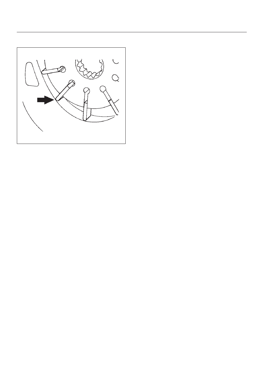
3. Install the vanes to roter with curved face in contact

with the inner wall of cam.

442RS005

4. Install rotor and vanes to cam.
5. Install pin to front housing.
6. Install two new O-rings to front housing.  Be sure to

discard used O-ring.

7. Install side plate.

CAUTION: When installing side plate, be careful not
to damage its inner surface.  Damaged side plate may
cause poor pump performance, pump seizure or oil
leakage.

8. Install pump cartridge assembly to front housing.
9. Install snap ring to shaft end.

10. Install rear housing with a new O-ring.  Be sure to

discard used O-ring. Then install bolt and tighten it to
specified torque.

Torque: 24 N·m (17 lb ft)

11. Install suction pipe with a new O-ring. Be sure to

discard used O-ring. Then install bolt and tighten it to
specified torque.

Torque: 10 N·m (87 lb in)

12. Install relief valve and spring.
13. Install connector with a new O-ring.  Be sure to

discard used O-ring. Tighten the connector to
specified torque.

Torque: 59 N·m (43 lb ft)

14. Install pressure switch assembly and tighten it to

specified torque.

Torque: 18 N·m (13 lb ft)

POWER–ASSISTED STEERING SYSTEM

2A–27

Main Data and Specifications

General Specifications

Oil pump

Type

Vane

Operating
fluid

ATF DEXRON

–III

Torque Specifications

E02RX004

2A–28 POWER–ASSISTED STEERING SYSTEM

Transfer Gear Assembly

Transfer Gear Assembly and Associated Parts

441R200001

Legend

(1) Transfer Gear Assembly
(2) Bolt, Universal Joint (Steering Shaft Side)
(3) Fixing Bolt Nut

(4) Shim
(5) Universal Joint Assembly
(6) Bolt, Universal Joint (Steering Unit Side)

Removal

1. Apply a setting mark across the universal joint

(steering shaft side) and transfer gear assembly to
reassemble the parts in their original position.

2. Remove universal joint bolt (steering shaft side).
3. Apply a setting mark across the universal joint

assembly and the transfer gear assembly to
reassemble the parts in their original position.

4. Remove universal joint bolts (both of transfer gear

assembly side and power steering unit assembly
side).

5. Loosen fixing bolts and nut and remove transfer gear

assembly with shim.

Inspection and Repair

The transfer gear assembly cannot be disassembled. If
damage or abnormal condition are found, replace the
entire transfer gear assembly.

Installation

1. Install the transfer gear assembly to the universal

joint (steering shaft side) align the setting marks
made at removal.
Then tighten the universal joint bolt.

2. Install the universal joint assembly to the power

steering unit assembly align the setting marks made
at removal.
Then temporary tighten the universal joint bolt (both
of transfer gear assembly side and power steering
unit assembly side).

3. Install the transfer gear assembly with the shim to

frame.

Torque: 54 N·m (40 lb ft)

4. Tighten the universal joint bolts to the specified

torque.

Torque: 31 N·m (23 lb ft)

POWER–ASSISTED STEERING SYSTEM

2A–29

Supplemental Restraint System Steering Wheel & Column

Service Precaution

This steering wheel and column repair section covers the
Supplemental Restraint System (SRS) steering column.
The following repair procedures are specific to SRS
components. When servicing a vehicle equipped with
Supplemental Restraint System, pay close attention to all
WARNINGS and CAUTIONS.
For detailed explanation about SRS, refer to 

Restraints

section.

WARNING: THIS VEHICLE HAS A SUPPLEMENTAL
RESTRAINT SYSTEM (SRS).  REFER TO THE SRS
COMPONENT AND WIRING LOCATION VIEW IN
ORDER TO DETERMINE WHETHER YOU ARE
PERFORMING SERVICE ON OR NEAR THE SRS
COMPONENTS OR THE SRS WIRING.  WHEN YOU
ARE PERFORMING SERVICE ON OR NEAR THE SRS
COMPONENTS OR THE SRS WIRING, REFER TO
THE SRS SERVICE INFORMATION.  FAILURE TO
FOLLOW WARNINGS COULD RESULT IN POSSIBLE
AIR BAG DEPLOYMENT, PERSONAL INJURY, OR
OTHERWISE UNNEEDED SRS SYSTEM REPAIRS.

SAFE HANDLING OF INFLATOR MODULES
REQUIRES FOLLOWING THE PROCEDURES
DESCRIBED BELOW FOR BOTH LIVE AND
DEPLOYED MODULES.

SAFETY PRECAUTIONS MUST BE FOLLOWED
WHEN HANDLING A DEPLOYED AIR BAG
ASSEMBLY (AIR BAG).  AFTER DEPLOYMENT, THE
AIR BAG ASSEMBLY (AIR BAG) SURFACE MAY
CONTAIN A SMALL AMOUNT OF SODIUM
HYDROXIDE, A BY-PRODUCT OF THE
DEPLOYMENT REACTION, THAT IS IRRITATING TO
THE SKIN AND EYES.  MOST OF THE POWDER ON
THE AIR BAG ASSEMBLY (AIR BAG) IS HARMLESS.
AS A PRECAUTION, WEAR GLOVES AND SAFETY
GLASSES WHEN HANDLING A DEPLOYED AIR BAG
ASSEMBLY, AND WASH YOUR HANDS WITH MILD
SOAP AND WATER AFTERWARDS.

WHEN CARRYING A LIVE AIR BAG ASSEMBLY,
MAKE SURE THE BAG AND TRIM COVER ARE
POINTED AWAY FROM YOU.  NEVER CARRY AN AIR
BAG ASSEMBLY BY THE WIRES OR CONNECTOR
ON THE UNDERSIDE OF MODULE.  IN THE CASE OF
AN ACCIDENTAL DEPLOYMENT, THE BAG WILL
THEN DEPLOY WITH MINIMAL CHANCE OF INJURY.
WHEN PLACING A LIVE AIR BAG ASSEMBLY ON A
BENCH OR OTHER SURFACE, ALWAYS FACE THE
BAG AND TRIM COVER UP, AWAY FROM THE
SURFACE.

NEVER REST A STEERING COLUMN ASSEMBLY ON
THE STEERING WHEEL WITH THE AIR BAG
ASSEMBLY FACE DOWN AND COLUMN VERTICAL.
THIS IS NECESSARY SO THAT A FREE SPACE IS
PROVIDED TO ALLOW THE AIR BAG ASSEMBLY TO
EXPAND IN THE UNLIKELY EVENT OF ACCIDENTAL
DEPLOYMENT.  OTHERWISE, PERSONAL INJURY
COULD RESULT.

TO AVOID DEPLOYMENT WHEN
TROUBLESHOOTING THE SRS SYSTEM, DO NOT
USE ELECTRICAL TEST EQUIPMENT, SUCH AS
BATTERY-POWERED OR A/C-POWERED
VOLT-METER, OHMMETER, ETC., OR ANY TYPE OF
ELECTRICAL EQUIPMENT OTHER THAN
SPECIFIED IN THIS MANUAL.  DO NOT USE A
NON-POWERED PROBE-TYPE TESTER.

INSTRUCTIONS IN THIS MANUAL MUST BE
FOLLOWED CAREFULLY, OTHERWISE PERSONAL
INJURY MAY RESULT.

SRS Connectors

CAUTION: The special yellow color connectors are
used for supplemental restraint system-air bag
circuit.
When removing the cable harness disconnect the
connector by unlocking at two places, outside (1)
and inside (2). Do not pull the wires or disconnection
may occur.
When connecting the double lock type SRS connec-
tor, insert the connector completely then lock the
connector.  Imperfect locking may cause the SRS cir-
cuit to malfunction.


Content   ..  43  44  45  46   ..