Isuzu Amigo / Axiom / Trooper / Rodeo / VehiCross. Manual - part 44


  Index      Isuzu     Isuzu Amigo / Axiom / Trooper / Rodeo / VehiCross - service repair manual 1999-2002 year


Search            


Content   ..  42  43  44  45   ..


Isuzu Amigo / Axiom / Trooper / Rodeo / VehiCross. Manual - part 44


2A–22 POWER–ASSISTED STEERING SYSTEM

Main Data and Specifications

General Specifications

Power Steering unit

Type

Rack and pinion

Rack stroke

152 mm (5.98 in)

Lock to lock

3.64

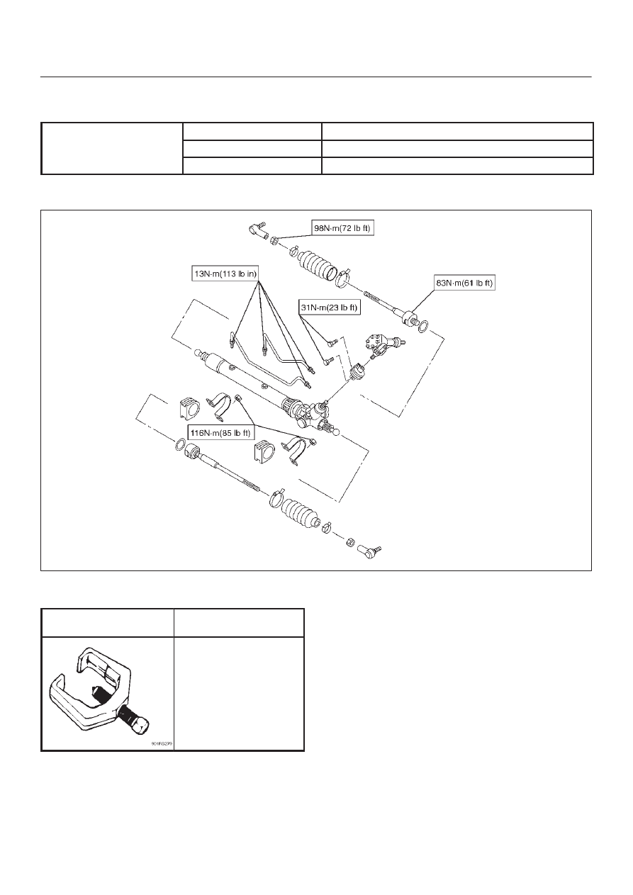
Torque Specifications

440R100003

Special Tools

ILLUSTRATION

TOOL NO.

TOOL NAME

J–29107

Tie rod end remover

POWER–ASSISTED STEERING SYSTEM

2A–23

Power Steering Pump

Power Steering Pump and Associated Parts

436RX001

Legend

(1) Pump Assembly
(2) Hose, Suction

(3) Hose, Flexible
(4) Bolt

Removal

1. Remove the drive belt.
2. Place a drain pan below the pump.
3. Disconnect the suction hose.
4. Disconnect the flexible hose.
5. Remove the power steering fixing bolt and remove

the pump assembly.

Installation

1. Install the pump assembly to the pump braket, tighten

the fixing bolt to the specified torque.

Torque: 46 N·m (34 lb ft)

2. Install the flexible hose.

Tighten the eye bolt to specified torque.

Torque: 54 N·m (40 lb ft)

3. Install the drive belt.
4. Connect the suction hose, then fill and bleed system.

Refer to 

Bleeding the Power Steering System in this

section.

2A–24 POWER–ASSISTED STEERING SYSTEM

Power Steering Pump Disassembled View

442RX001

Legend

(1) Bolt
(2) Suction Pipe
(3) O-ring
(4) Shaft Assembly
(5) Oil Seal
(6) Front Housing
(7) O-ring
(8) O-ring
(9) Side Plate

(10) Rotor and Vane

(11) Pin

(12) Cam
(13) Pump Cartridge Assembly
(14) O-ring
(15) Snap Ring
(16) Rear Housing
(17) Bolt
(18) Spring
(19) Relief Valve
(20) O-ring
(21) Connector
(22) Pressure Switch Assembly

Disassembly

1. Clean the oil pump with solvent (plug the discharge

and suction ports to prevent the entry of solvent).
Be careful not to expose the oil seal of shaft assembly
to solvent.

2. Remove the bolt, suction pipe and O-ring.
3. Remove the connector, O-ring, relief valve and

spring.

4. Remove the pressure switch assembly.
5. Remove the bolt, rear housing and O-ring.
6. Remove the snap ring.

7. Remove the shaft assembly.
8. Remove the oil seal.

CAUTION: When removing the oil seal, be careful
not to damage the housing.

9. Remove the pump cartridge assembly from the front

housing.

10. Remove two O-rings.

POWER–ASSISTED STEERING SYSTEM

2A–25

Inspection and Repair

Make all necessary adjustments, repairs, and part
replacements if wear, damage, or other problems are
discovered during inspection.

Rotor

442RS002

Check that the groove in the vane is free from excessive
wear and that the vane slides smoothly. When part
replacement becomes necessary, the pump cartridge
should be replaced as a subassembly.

Vane

442RS003

Sliding faces of the vane should be free from wear.
(Particularly the curved face at the tip that contact with the
cam should be free from wear and distortion). When part
replacement becomes necessary, the pump cartridge
should be replaced as a subassembly.

Cam

The inner face of the arm should have a uniform contact
pattern without a sign of step wear. When part
replacement becomes necessary, the pump cartridge
should be replaced as a subassembly.

Side Plate

The sliding faces of parts must be free from step wear
(more than 0.01 mm), which can be felt by the finger nail.
The parts with minor scores may be reused after lapping
the face.

Relief Valve

The sliding face of the valve must be free from burrs and
damage. The parts with minor scores may be reused after
smoothing with emery cloth (#800 or finer).

Shaft

Oil seal sliding faces must be free from a step wear which
can be felt by the finger nail. Bushing fitting face must be
free from damage and wear.

O-ring, Oil Seal, Snap Ring

Be sure to discard used parts, and always use new parts
for installation.  Prior to installation, lubricate all seals and
rings with power steering fluid.

Pressure Switch

Check the switch operation as follows:
With engine idling and A/C on, turn the steering wheel
fully to the left; compressor should interrupt and engine
idle speed will increase. Shut off A/C and again turn
steering fully to the left; engine idle will increase. If system
fails to function properly, disconnect connector at the
pressure switch and repeat system check while testing
continuity across disconnected SW connector.

Reassembly

1. Install oil seal to front housing.  Be sure to discard

used oil seal, and always use new parts for
installation.

CAUTION: When installing the oil seal, be careful
not to damage the oil seal contacting surface of the
housing.

2. Install shaft assembly.


Content   ..  42  43  44  45   ..