Infiniti QX4 (R50). Manual - part 585
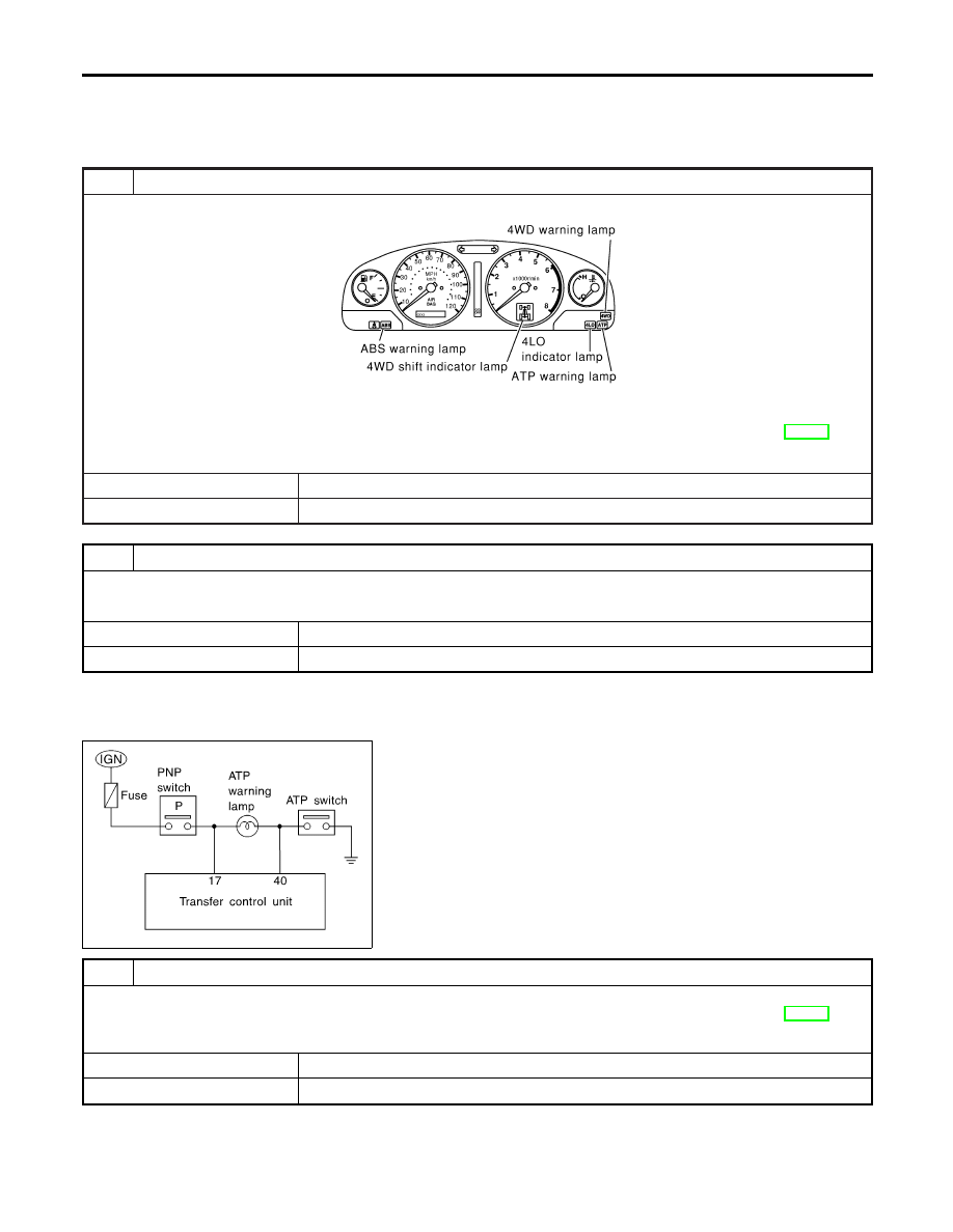
Symptom 3. 4WD Shift Indicator Lamp Does
Not Turn OFF
NBTF0031
SYMPTOM: When 4WD shift switch is set from “4H” to
“4LO”, all the 4WD shift indicator lamps do not turn OFF.
1
CHECK ATP SWITCH CIRCUIT
SMT958D
Check ATP switch circuit.
Refer to “Diagnostic Procedure”, “ATP SWITCH, WAIT DETECTION SWITCH AND NEUTRAL-4LO SWITCH”, TF-112.
OK or NG
OK
©
GO TO 2.
NG
©
Check, repair or replace faulty parts.
2
CHECK PROCEDURE FROM THE BEGINNING AGAIN
Check again.
OK or NG
OK
©
INSPECTION END
NG
©
Recheck each connector’s pin terminals for damage or loose connection.
SMT856D
Symptom 4. ATP Warning Lamp Does Not Turn
ON
NBTF0032
SYMPTOM: When 4WD shift switch is set from “4H” to
“4LO” with A/T selector lever in “P” position, ATP warning
lamp does not turn ON.
1
CHECK ATP SWITCH CIRCUIT
Check ATP switch circuit.
Refer to “Diagnostic Procedure”, “ATP SWITCH, WAIT DETECTION SWITCH AND NEUTRAL-4LO SWITCH”, TF-112.
OK or NG
OK
©
GO TO 2.
NG
©
Check, repair or replace faulty parts.
TROUBLE DIAGNOSES FOR SYMPTOMS
Symptom 3. 4WD Shift Indicator Lamp Does Not Turn OFF
TF-102