Infiniti QX4 (R50). Manual - part 317
MEL786L
GI
MA
EM
LC
EC
FE
AT
TF
PD
AX
SU
BR
ST
RS
BT
HA
SC
IDX
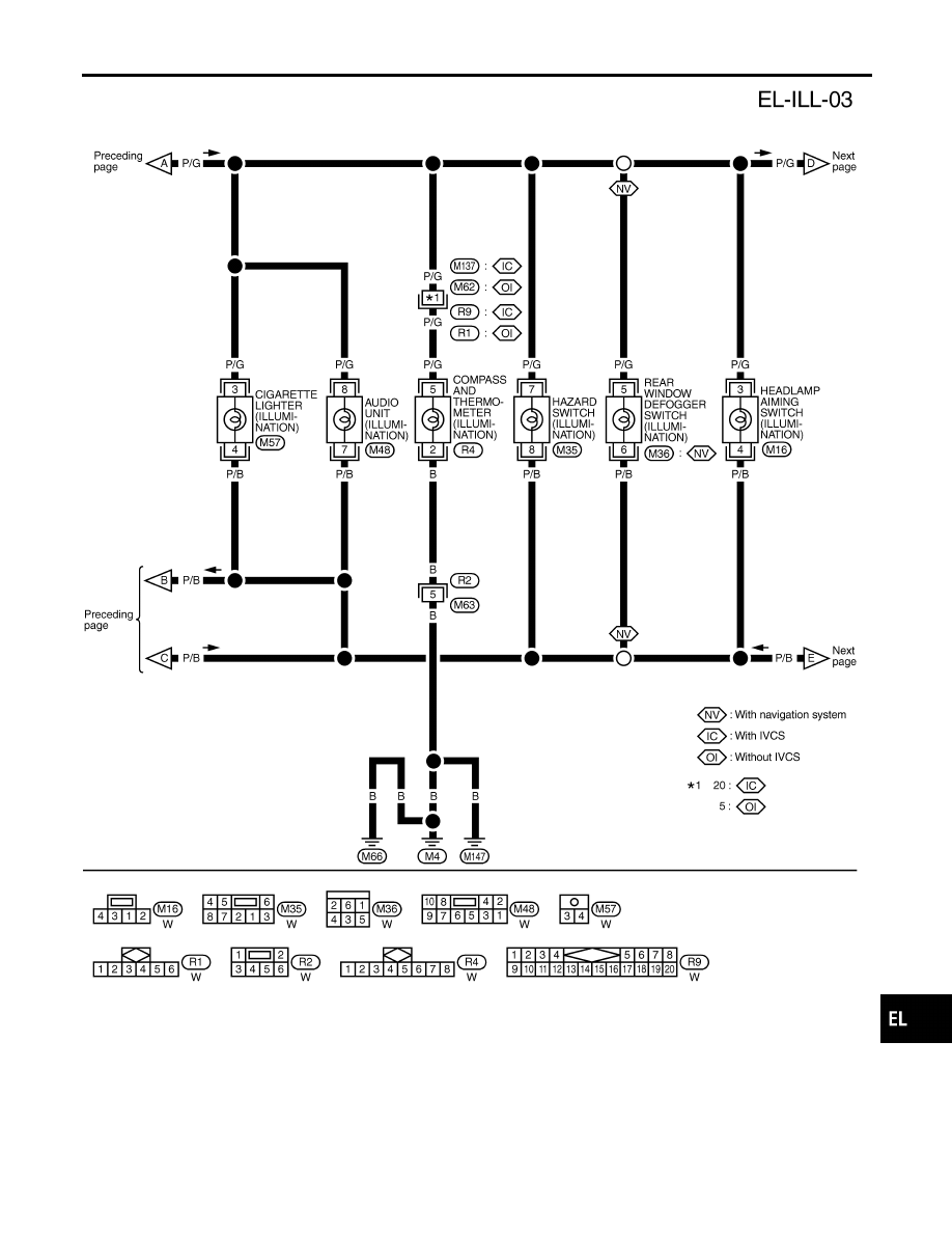
ILLUMINATION
Wiring Diagram — ILL — (Cont’d)
EL-85
|
|
|
MEL786L GI MA EM LC EC FE AT TF PD AX SU BR ST RS BT HA SC IDX ILLUMINATION Wiring Diagram — ILL — (Cont’d) EL-85 |