Infiniti QX4 (R50). Manual - part 255
Diagnostic Procedure
NBEC0712
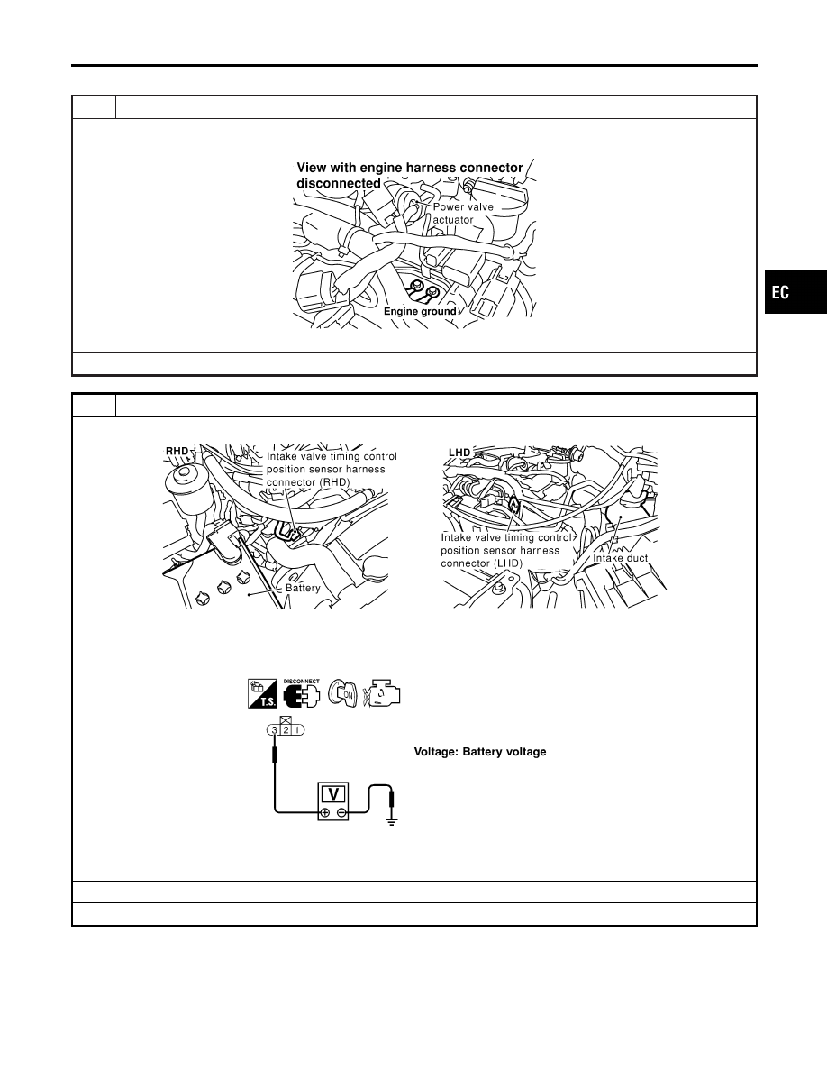
1
RETIGHTEN GROUND SCREWS
1. Turn ignition switch “OFF”.
2. Loosen and retighten engine ground screws.
SEF959Y
©
GO TO 2.
2
CHECK INTAKE VALVE TIMING CONTROL POSITION SENSOR POWER SUPPLY CIRCUIT
1. Disconnect intake valve timing control position sensor harness connector.
SEF360Z
2. Turn ignition switch “ON”.
3. Check voltage between intake valve timing control position sensor harness connector terminal 3 and ground with CON-
SULT-II or tester.
SEF370X
4. Also check harness for short to ground and short to power.
OK or NG
OK
©
GO TO 4.
NG
©
GO TO 3.
GI
MA
EM
LC
FE
AT
TF
PD
AX
SU
BR
ST
RS
BT
HA
SC
EL
IDX
DTC P1140 (RIGHT, -B1), P1145 (LEFT, -B2) INTAKE VALVE TIMING CONTROL
POSITION SENSOR (CIRCUIT)
Diagnostic Procedure
EC-487