Infiniti QX4 (R50). Manual - part 72
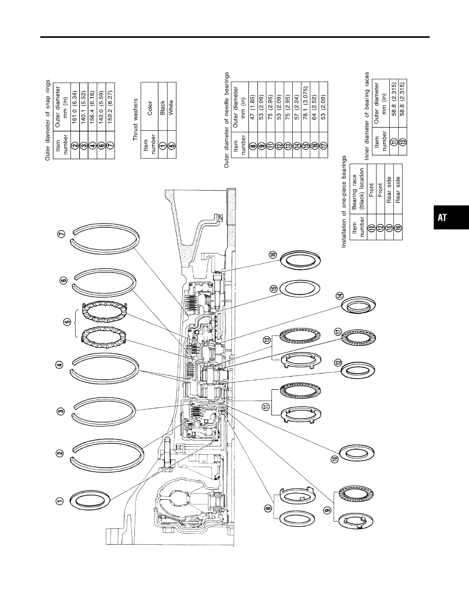
Locations of Needle Bearings, Thrust Washers
and Snap Rings
NBAT0110
SAT140JB
GI
MA
EM
LC
EC
FE
TF
PD
AX
SU
BR
ST
RS
BT
HA
SC
EL
IDX
OVERHAUL
Locations of Needle Bearings, Thrust Washers and Snap Rings
AT-285
|
|
|
Locations of Needle Bearings, Thrust Washers NBAT0110 SAT140JB GI MA EM LC EC FE TF PD AX SU BR ST RS BT HA SC EL IDX OVERHAUL Locations of Needle Bearings, Thrust Washers and Snap Rings AT-285 |