Infiniti QX4 (R50). Manual - part 70


  Index      Infiniti     Infiniti QX4 (R50) - service repair manual 2001 year


Search            copyright infringement  


Content   ..  68  69  70  71   ..


Infiniti QX4 (R50). Manual - part 70


Removal

NBAT0214

SAT362IA

SAT163K

CAUTION:

When removing the A/T assembly from engine, first remove
the crankshaft position sensor (OBD) from the A/T assembly
lower side.
Be careful not to damage sensor edge.
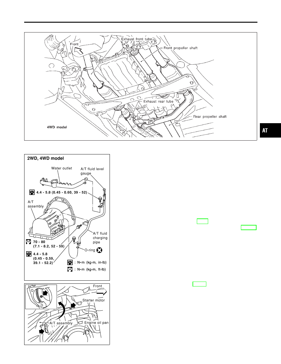
— 4WD MODEL —

NBAT0214S01

1.

Remove battery negative terminal.

2.

Remove exhaust front and rear tubes.

3.

Remove fluid charging pipe from A/T assembly.

4.

Remove oil cooler pipe from A/T assembly.

5.

Plug up openings such as the fluid charging pipe hole, etc.

6.

Remove propeller shaft. Refer to PD-4, “Components”.

7.

Remove transfer control linkage from transfer. Refer to TF-119,
“Removal”.

I

Insert plug into rear oil seal after removing rear propeller
shaft.

I

Be careful not to damage spline, sleeve yoke and rear oil
seal.

8.

Remove A/T control cable from A/T assembly.

9.

Disconnect A/T solenoid, PNP switch, turbine revolution, revo-
lution and speedometer sensor harness connectors.

SAT148K

10. Remove starter motor. Refer to SC-18, “Removal and Installa-

tion”.

11. Remove bolts securing torque converter to drive plate.

I

Remove the bolts by turning crankshaft.

GI

MA

EM

LC

EC

FE

TF

PD

AX

SU

BR

ST

RS

BT

HA

SC

EL

IDX

REMOVAL AND INSTALLATION

Removal

AT-277

SAT801C

12. Support A/T and transfer assembly with a jack.
13. Remove rear engine mounting member from body and A/T

assembly. Tighten rear engine mounting member to the speci-
fied torque. Refer to EM-59, “Rear Engine Mounting”.

14. Remove bolts securing A/T assembly to engine.

I

Secure torque converter to prevent it from dropping.

I

Secure A/T assembly to a jack.

15. Lower A/T assembly with transfer.

SAT553J

SAT544J

— 2WD MODEL —

NBAT0214S02

CAUTION:

I

Do not attach lifting cable to or place supporting fixture
under companion flange at rear of A/T (shown in the fig-
ure at left) when lifting/lowering A/T.

I

Be sure to attach lifting cable to rear engine mounting or
dynamic damper location when lifting/lowering A/T.

1.

Remove battery negative terminal.

2.

Remove exhaust front and rear tubes.

3.

Remove fluid charging pipe from A/T assembly.

4.

Remove oil cooler pipe from A/T assembly.

5.

Plug up openings such as the fluid charging pipe hole, etc.

6.

Remove propeller shaft. Refer to PD-4, “Components”.

7.

Remove A/T control cable from A/T assembly.

8.

Disconnect A/T and speedometer sensor harness connectors.

9.

Remove starter motor. Refer to SC-18, “Removal and Installa-
tion”.

10. Remove gusset and rear plate cover securing engine to A/T

assembly.

11. Remove bolts securing torque converter to drive plate.

I

Remove the bolts by turning crankshaft.

12. Support A/T assembly with a jack.
13. Remove rear engine mounting member from body and A/T

assembly. Tighten rear engine mounting member to the speci-
fied torque. Refer to EM-59, “Rear Engine Mounting”.

14. Remove bolts securing A/T assembly to engine.
15. Pull A/T assembly backwards.

I

Secure torque converter to prevent it from dropping.

I

Secure A/T assembly to a jack.

16. Lower A/T assembly.

SAT977H

Installation

NBAT0107

I

Drive plate runout

Maximum allowable runout:

Refer to EM-70, “FLYWHEEL/DRIVE PLATE RUNOUT”.

If this runout is out of specification, replace drive plate with ring
gear.

REMOVAL AND INSTALLATION

Removal (Cont’d)

AT-278

SAT017B

I

When connecting torque converter to transmission, measure
distance “A” to be certain that they are correctly assembled.

Distance “A”:

25.0 mm (0.984 in) or more

SAT148K

I

Install converter to drive plate.

I

After converter is installed to drive plate, rotate crankshaft
several turns and check to be sure that transmission
rotates freely without binding.

SAT149K

I

Tighten bolts securing transmission.

Bolt No.

Tightening torque

N·m (kg-m, ft-lb)

Bolt length “


mm (in)

1

70 - 80 (7.1 - 8.2, 52 - 59)

65 (2.56)

2

70 - 80 (7.1 - 8.2, 52 - 59)

55 (2.17)

3

29 - 39 (3.0 - 4.0, 22 - 29)

40 (1.57)

I

Reinstall any part removed.

SAT638A

I

Check fluid level in transmission.

I

Move selector lever through all positions to be sure that trans-
mission operates correctly.
With parking brake applied, rotate engine at idling. Move selec-
tor lever through “N” to “D”, to “2”, to “1” and to “R” positions.
A slight shock should be felt by hand gripping selector each
time transmission is shifted.

I

Perform road test. Refer to “ROAD TEST”, AT-63.

GI

MA

EM

LC

EC

FE

TF

PD

AX

SU

BR

ST

RS

BT

HA

SC

EL

IDX

REMOVAL AND INSTALLATION

Installation (Cont’d)

AT-279

AIR BREATHER HOSE

NBAT0107S01

SAT152K

SAT153K

REMOVAL AND INSTALLATION

Installation (Cont’d)

AT-280


Content   ..  68  69  70  71   ..