Infiniti Q45 (FY33). Manual - part 510
SPD376AA
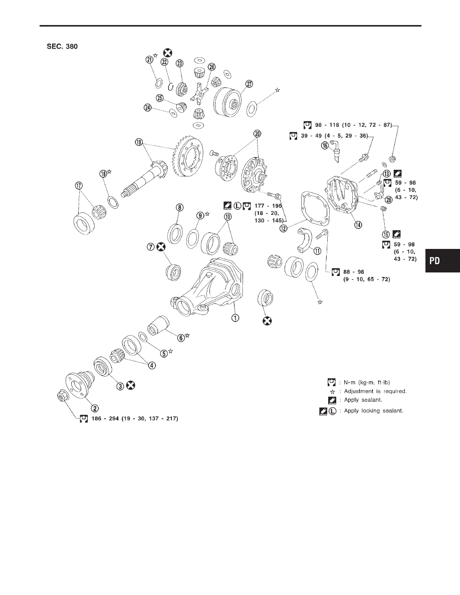
q
1
Gear carrier
q
2
Companion flange
q
3
Front oil seal
q
4
Pinion front bearing
q
5
Pinion bearing adjusting washer
q
6
Pinion bearing adjusting spacer
(Solid spacer)
q
7
Side oil seal
q
8
Side bearing spacer
q
9
Side bearing adjusting washer
q
10
Side bearing
q
11
Bearing cap
q
12
Gasket
q
13
Drain plug
q
14
Rear cover
q
15
Filler plug
q
16
Breather
q
17
Pinion rear bearing
q
18
Pinion height adjusting washer
q
19
Hypoid gear set
q
20
Differential case
q
21
Side gear thrust washer
q
22
Circular clip
q
23
Side gear (RH)
q
24
Pinion mate thrust washer
q
25
Pinion mate gear
q
26
Pinion mate shaft
q
27
Side gear (LH) with viscous cou-
pling
q
28
TCS sensor
GI
MA
EM
LC
EC
FE
AT
FA
RA
BR
ST
RS
BT
HA
EL
IDX
FINAL DRIVE
PD-13