Infiniti Q45 (FY33). Manual - part 327


  Index      Infiniti     Infiniti Q45 (FY33) - service repair manual 2001 year


Search            copyright infringement  


Content   ..  325  326  327  328   ..


Infiniti Q45 (FY33). Manual - part 327


SEL567U

On board Diagnosis — Mode II (Switch
monitor)

HOW TO PERFORM MODE II

Condition

I

Ignition switch: OFF

I

Lighting switch: OFF

I

Rear window defogger switch: OFF

I

Doors: Closed

I

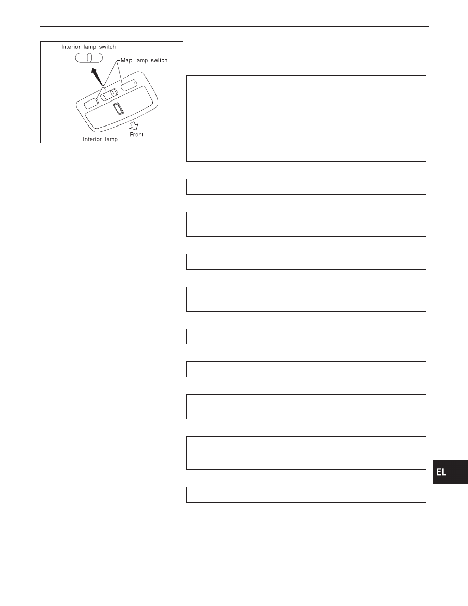
Interior lamp switch: AUTO

I

Driver side map lamp switch: OFF

I

Passenger side map lamp switch: OFF

I

Selector lever: “P” range

Turn ignition switch “ON”.

Return ignition switch to “ACC” and press rear window defogger switch

more than 10 times during 10 seconds.

Self-diagnostic results indicator lamps should turn on.

Keep rear window defogger switch pressed, and turn ignition switch “ON”

within 5 seconds after the indicator lamps turn on.

Indicator lamps turn ON.

Mode II can be performed.

Turn each switch ON and OFF. Note that the indicator lamp and/or buzzer
goes on or off in response to switch position.

Turn ignition switch “OFF”.

or

Drive the vehicle more than 7 km/h (4 MPH).

DIAGNOSIS END

GI

MA

EM

LC

EC

FE

AT

PD

FA

RA

BR

ST

RS

BT

HA

IDX

IVMS (LAN)

H

H

H

H

H

H

H

H

H

EL-299

DESCRIPTION

In this mode, when BCM detects the input signal from a switch in IVMS as shown below, the detection is indi-
cated by the front map lamp and front step lamps with buzzer.

SEL960V

SWITCH MONITOR ITEM

BCM

I

Lighting switch (1st)

I

Lighting switch (AUTO)

I

Wiper switch (INT)

I

Wiper switch (WASH)

I

Door switch (driver’s side)

I

Door switch (passenger side)

I

Door switch (Rear LH)

I

Door switch (Rear RH)

I

Rear window defogger switch

I

Detention switch

I

Driver’s side seat belt buckle switch

I

Trunk room lamp switch

I

Hood switch

I

Trunk lid key cylinder switch (UNLOCK)

I

Steering tilt switch (UP/DOWN)

I

Steering telescopic switch (FORWARD/
BACKWARD)

I

Auto drive positioner cancel switch

I

Seat memory switch-1

I

Seat memory switch-2

I

Seat set switch

I

Multi remote controller switch

LCU 01

I

Power window lock switch

I

Power window main switches (UP/DOWN)

I

Power window automatic switch

I

Door lock & unlock switch (LOCK/
UNLOCK)

I

Door unlock sensor

LCU 02

I

Door unlock sensor

I

Passenger power window sub-switch (UP/
DOWN)

LCU 03

I

Door unlock sensor

I

Power window sub-switch (Rear RH) (UP/
DOWN)

LCU 04

I

Door unlock sensor

I

Power window sub-switch (Rear LH) (UP/
DOWN)

LCU 05

Power seat switch
(Driver’s side)

I

Slide switch (FR/
RR)

I

Reclining switch
(FR/RR)

I

Front lifter switch
(UP/DOWN)

I

Rear lifter switch
(UP/DOWN)

IVMS (LAN)

On board Diagnosis — Mode II (Switch
monitor) (Cont’d)

EL-300

Schematic

POWER SUPPLY, GROUND AND COMMUNICATION CIRCUITS

TEL030M

GI

MA

EM

LC

EC

FE

AT

PD

FA

RA

BR

ST

RS

BT

HA

IDX

IVMS (LAN)

EL-301

Wiring Diagram — COMM —

POWER SUPPLY, GROUND AND COMMUNICATION CIRCUITS

TEL132M

IVMS (LAN)

EL-302


Content   ..  325  326  327  328   ..