Infiniti Q45 (FY33). Manual - part 326


  Index      Infiniti     Infiniti Q45 (FY33) - service repair manual 2001 year


Search            copyright infringement  


Content   ..  324  325  326  327   ..


Infiniti Q45 (FY33). Manual - part 326


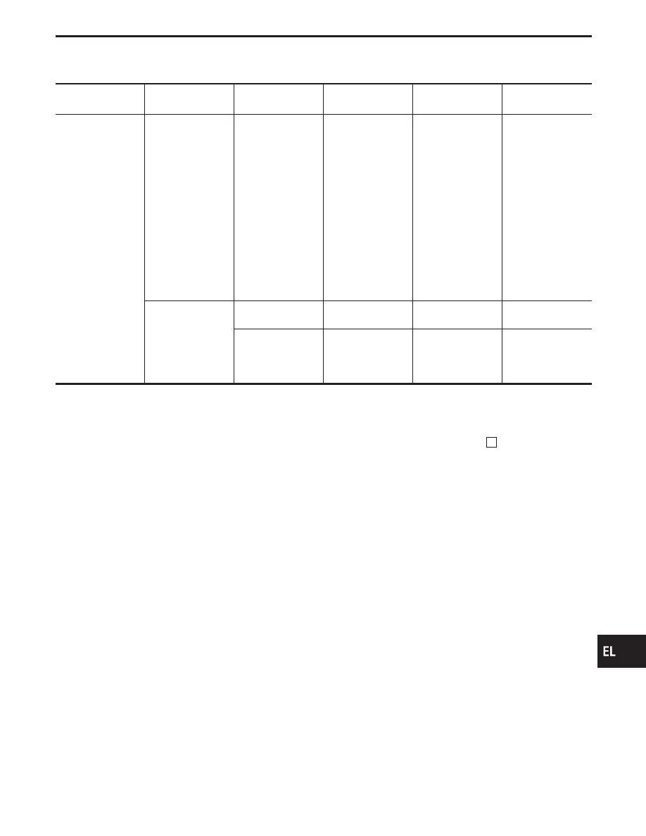
IVMS COMMUNICATION DIAGNOSES RESULTS LIST —
3

Diagnostic item

Number of malfunc-
tioning LCU

CONSULT-II diagno-
sis result

On board diagnosis
(Mode 1) code No.

Expected cause

Service procedure

Sleep control of
LCU is malfunction-
ing

One

POWER WINDOW
C/U-DR
[SLEEP]
POWER WINDOW
C/U-AS
[SLEEP]
POWER WINDOW
C/U-RR
[SLEEP]
POWER WINDOW
C/U-RL
[SLEEP]
POWER SEAT
C/U-DR
[SLEEP]

1. Malfunctioning

LCU

1. Replace LCU.*

Two or more

Combination of
above results

1. Malfunctioning

LCU

1. Replace LCU.*

All of above results

1. Malfunctioning

BCM

2. Malfunctioning all

LCUs

1. Replace BCM.*
2. Replace all

LCUs.*

*: Before replacing BCM/LCU, clear the memory of diagnoses result and perform communication diagnoses again.

If the diagnoses result is still NG, replace BCM/LCU.

NOTE: When CONSULT-II indicates [PAST COMM FAIL] or [PAST NO RESPONSE], erase the memory and perform communication

diagnoses again.
To erase the memory, perform the procedure below.
Erase the memory by CONSULT-II or turn the ignition to “OFF” position and remove 7.5A fuse [No.

14

, located in the fuse

block (J/B)].

GI

MA

EM

LC

EC

FE

AT

PD

FA

RA

BR

ST

RS

BT

HA

IDX

IVMS (LAN)

CONSULT-II (Cont’d)

EL-295

SEL598U

On board Diagnosis

ON BOARD DIAGNOSTIC RESULTS INDICATOR LAMP

Front map lamps and step lamps (all seats) act as the indicators
for the on board diagnosis Mode I, II and III. Seat memory indica-
tor-1 and 2 act as the indicators for the on board diagnosis Mode
IV. These lamps blink simultaneously in response to diagnostic
results.

SEL071V

ON BOARD DIAGNOSTIC FUNCTION

Mode

Function

Self-diagnostic results indicator lamp

Reference

page

Interior lamp

Step lamps

(all seats)

Automatic

drive positioner
indicator lamps

Mode I

IVMS commu-

nication diag-

nosis

Diagnosing any abnormality or
inability of communication
between BCM and LCUs
(DATA LINES A-1, A-2 and
A-3).

X

X

EL-297

Mode II

Switch monitor

Monitoring conditions of
switches connected to BCM
and LCUs.

X

X

EL-299

Mode III

Power door

lock self-diag-

nosis

X

X

EL-342

Mode IV

Automatic

drive positioner

self-diagnosis

X

EL-458

X: Applicable
—: Not applicable

NOTE:

I

When on board diagnosis Mode I, II or III is operating, all systems under IVMS control do not oper-

ate.

I

When on board diagnosis Mode IV is operating, automatic drive positioner does not operate.

I

The step lamp of malfunctioning LCU does not blink.

IVMS (LAN)

EL-296

SEL567U

On board Diagnosis — Mode I (IVMS
communication diagnosis)

HOW TO PERFORM MODE I

Condition

I

Ignition switch: OFF

I

Lighting switch: OFF

I

Rear window defogger switch: OFF

I

Doors: Closed

I

Interior lamp switch: AUTO

I

Driver side map lamp switch: OFF

I

Passenger side map lamp switch: OFF

I

Selector lever: “P” range

Turn ignition switch “ON”.

Return ignition switch to “ACC” and press rear window defogger switch

more than 10 times during 10 seconds.

Self-diagnostic results indicator lamps should turn on.

Rear window defogger switch holds OFF.

Turn ignition switch “ON” within 5 seconds after the indicator lamps turn on.

Indicator lamp turn off.

After a second

Mode I is performed.

Turn ignition switch “OFF”.

or

Drive the vehicle more than 7 km/h (4 MPH).

DIAGNOSIS END*

*: Diagnosis ends after self-diagnostic results have been indicated for 10 min-

utes if left unattended.

GI

MA

EM

LC

EC

FE

AT

PD

FA

RA

BR

ST

RS

BT

HA

IDX

IVMS (LAN)

H

H

H

H

H

H

H

H

H

EL-297

DESCRIPTION

In this mode, a malfunction code is indicated by the number of flashes from the front map lamps and step
lamps as shown below:

SEL471T

After indicator lamp turns on for 2 seconds then off for 2 seconds, it flashes [cycling ON (0.5 sec.)/OFF (0.5
sec.)] to indicate a malfunction code of the first digit. Then, 1 second after indicator lamp turns off, it again
flashes [cycling ON (0.5 sec.)/OFF (0.5 sec.)] to indicate a malfunction code of the second digit.
For example, the indicator lamp goes on and off for 0.5 seconds twice and after 1.0 seconds, it goes on and
off for 0.5 seconds four times. This indicates malfunction code “24”.

MALFUNCTION CODE TABLE

Code No.

Malfunctioning LCU

Detected items

Diagnostic procedure

24

Driver door control unit
(LCU01)

Malfunctioning communication

Refer to CONSULT-II DIAGNOSTIC CHART,
“COMM FAIL” (EL-293).

25

No response from data line A-1

Refer to CONSULT-II DIAGNOSTIC CHART,
“NO RESPONSE” (EL-294).

34

Passenger door control
unit (LCU02)

Malfunctioning communication

Refer to CONSULT-II DIAGNOSTIC CHART,
“COMM FAIL” (EL-293).

35

No response from data line A-2

Refer to CONSULT-II DIAGNOSTIC CHART,
“NO RESPONSE” (EL-294).

41

Rear RH door control unit
(LCU03)

Malfunctioning communication

Refer to CONSULT-II DIAGNOSTIC CHART,
“COMM FAIL” (EL-293).

42

No response from data line A-1

Refer to CONSULT-II DIAGNOSTIC CHART,
“NO RESPONSE” (EL-294).

44

Rear LH door control unit
(LCU04)

Malfunctioning communication

Refer to CONSULT-II DIAGNOSTIC CHART,
“COMM FAIL” (EL-293).

45

No response from data line A-2

Refer to CONSULT-II DIAGNOSTIC CHART,
“NO RESPONSE” (EL-294).

47

Driver’s seat control unit
(LCU05)

Malfunctioning communication

Refer to CONSULT-II DIAGNOSTIC CHART,
“COMM FAIL” (EL-293).

48

No response from data line A-3

Refer to CONSULT-II DIAGNOSTIC CHART,
“NO RESPONSE” (EL-294).

11

No malfunction

IVMS (LAN)

On board Diagnosis — Mode I (IVMS
communication diagnosis) (Cont’d)

EL-298


Content   ..  324  325  326  327   ..