Infiniti Q45 (FY33). Manual - part 36


  Index      Infiniti     Infiniti Q45 (FY33) - service repair manual 2001 year


Search            copyright infringement  


Content   ..  34  35  36  37   ..


Infiniti Q45 (FY33). Manual - part 36


SAT739J

SAT945IA

q

A

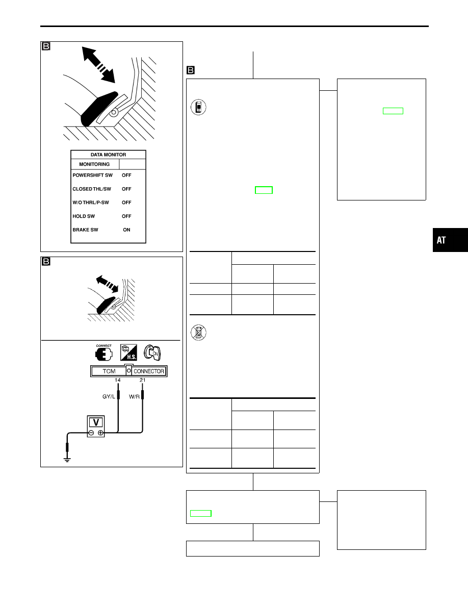
CHECK THROTTLE POSITION SWITCH
CIRCUIT.

1. Turn ignition switch to “ON”

position.
(Do not start engine.)

2. Select “TCM INPUT SIGNALS”

in “DATA MONITOR” mode for
A/T with CONSULT-II.

3. Apply vacuum to the throttle

opener. Refer to steps 1 and 2
of “Preparation”, “TCM SELF-
DIAGNOSTIC PROCEDURE
(No Tools)”, AT-49.

4. Read out “CLOSED THL/SW”

and “W/O THRL/P-SW”
depressing and releasing accel-
erator pedal.
Check the signal of throttle posi-
tion switch is indicated properly.

-------------------------------------------------------------------------------------------------------------------------------------- OR --------------------------------------------------------------------------------------------------------------------------------------

1. Turn ignition switch to “ON”

position.
(Do not start engine.)

2. Check voltage between TCM

terminals

q

14

,

q

21

and ground

while depressing, and releasing
accelerator pedal slowly. (After
warming up engine)

OK

E

NG

Check the following items:

I

Throttle position switch
Refer to “Components
Inspection”, AT-142.

I

Harness for short or
open between ignition
switch and throttle posi-
tion switch (Main har-
ness)

I

Harness for short or
open between throttle
position switch and TCM
(Main harness)

Perform DIAGNOSTIC TROUBLE CODE
(DTC) CONFIRMATION PROCEDURE,
AT-139.

OK

E

NG

1. Perform TCM input/

output signal inspection.

2. If NG, recheck TCM pin

terminals for damage or
loose connection with
harness connector.

INSPECTION END

Accelerator

pedal condi-

tion

Data monitor

CLOSED

THL/SW

W/O THRL/

P-SW

Released

ON

OFF

Fully

depressed

OFF

ON

Accelrator

pedal condi-

tion

Voltage

Terminal No.

q

14

Terminal No.

q

21

Released

Battery volt-

age

1V or less

Fully

depressed

1V or less

Battery volt-

age

GI

MA

EM

LC

EC

FE

PD

FA

RA

BR

ST

RS

BT

HA

EL

IDX

TROUBLE DIAGNOSIS FOR DTC P1705

Throttle Position Sensor (Cont’d)

H

H

H

AT-141

SAT521I

COMPONENT INSPECTION

Throttle position switch

Closed throttle position switch (idle position)

I

Check continuity between terminals

q

5

and

q

7

. (Refer to

“Preparation”, “TCM SELF-DIAGNOSTIC PROCEDURE (No
Tools)”, AT-49.)

Accelerator pedal condition

Continuity

Released

Yes

Depressed

No

I

To adjust closed throttle position switch, refer to EC section
(“Basic Inspection”, “TROUBLE DIAGNOSIS — Basic Inspec-
tion”).

SAT102J

Wide open throttle position switch

I

Check continuity between terminals

q

6

and

q

7

.

Accelerator pedal condition

Continuity

Released

No

Depressed

Yes

TROUBLE DIAGNOSIS FOR DTC P1705

Throttle Position Sensor (Cont’d)

AT-142

SAT341H

Overrun Clutch Solenoid Valve

DESCRIPTION

The overrun clutch solenoid valve is activated by the TCM in
response to signals sent from the PNP switch, overdrive control
switch, vehicle speed and throttle position sensors. The overrun
clutch operation will then be controlled.

TCM TERMINALS AND REFERENCE VALUE

Remarks: Specification data are reference values.

Terminal

No.

Wire color

Item

Condition

Judgement

standard

(Approx.)

8

L

Overrun clutch
solenoid valve

When overrun clutch solenoid valve
operates.

Battery voltage

When overrun clutch solenoid valve
does not operate.

0V

ON BOARD DIAGNOSIS LOGIC

Diagnostic trouble code

Malfunction is detected when ...

Check item (Possible cause)

: O/R CLTCH SOL/CIRC

TCM detects an improper voltage drop
when it tries to operate the solenoid
valve.

I

Harness or connectors
(The solenoid circuit is open or
shorted.)

I

Overrun clutch solenoid valve

: P1760

GI

MA

EM

LC

EC

FE

PD

FA

RA

BR

ST

RS

BT

HA

EL

IDX

TROUBLE DIAGNOSIS FOR DTC P1760

AT-143

SAT014K

SEF949Y

DIAGNOSTIC TROUBLE CODE (DTC) CONFIRMA-
TION PROCEDURE

CAUTION:

Always drive vehicle at a safe speed.
NOTE:
If “DIAGNOSTIC TROUBLE CODE CONFIRMATION PROCE-
DURE” has been previously conducted, always turn ignition
switch “OFF” and wait at least 5 seconds before conducting
the next test.
TESTING CONDITION:
Always drive vehicle on a level road to improve accuracy of
test.
After the repair, perform the following procedure to confirm the
malfunction is eliminated.

1)

Turn ignition switch “ON” and select “DATA MONITOR”
mode for “ENGINE” with CONSULT-II.

2)

Start engine.

3)

Accelerate vehicle to a speed of more than 10 km/h (6
MPH) in “D” position (OD “ON”).

4)

Release accelerator pedal completely in “D” position
(OD “OFF”).

------------------------------------------------------------------------------------------------------------------------------------------------------------------------------------------------------------------------------------------------------ OR ------------------------------------------------------------------------------------------------------------------------------------------------------------------------------------------------------------------------------------------------------

Follow the procedure “With CONSULT-II”.

TROUBLE DIAGNOSIS FOR DTC P1760

Overrun Clutch Solenoid Valve (Cont’d)

AT-144


Content   ..  34  35  36  37   ..