Infiniti Q45 (FY33). Manual - part 35
SAT559I
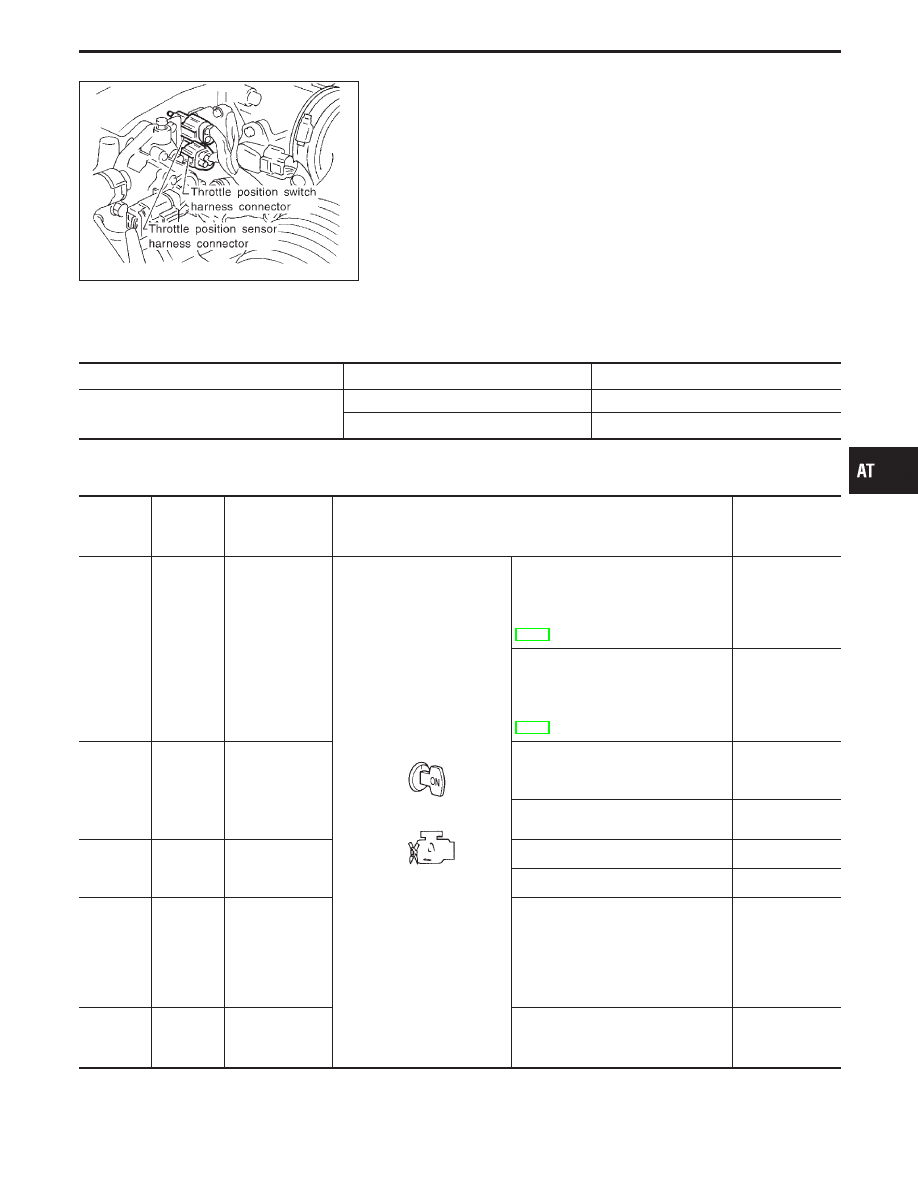
Throttle Position Sensor
DESCRIPTION
I
Throttle position sensor
The throttle position sensor detects the throttle valve position
and sends a signal to the TCM.
I
Throttle position switch
Consists of a wide open throttle position switch and a closed
throttle position switch.
The wide open throttle position switch sends a signal to the
TCM when the throttle valve is open at least 1/2 of the full
throttle position. The closed throttle position switch sends a
signal to the TCM when the throttle valve is fully closed.
CONSULT-II REFERENCE VALUE IN DATA MONITOR MODE
Remarks: Specification data are reference values.
Monitor item
Condition
Specification
Throttle position sensor
Fully-closed throttle
Approximately 0.5V
Fully-open throttle
Approximately 4V
TCM TERMINALS AND REFERENCE VALUE
Remarks: Specification data are reference values.
Terminal
No.
Wire color
Item
Condition
Judgement
standard
(Approx.)
14
GY/L
Closed throttle
position switch
(in throttle posi-
tion switch)
When releasing accelerator pedal
after warming up engine. (Refer to
“Preparation”, “TCM SELF-DIAG-
NOSTIC PROCEDURE (No Tools)”,
AT-49.)
Battery voltage
When depressing accelerator pedal
after warming up engine. (Refer to
“Preparation”, “TCM SELF-DIAG-
NOSTIC PROCEDURE (No Tools)”,
AT-49.)
0V
21
W/R
Wide open
throttle position
switch
(in throttle posi-
tion switch)
When depressing accelerator pedal
more than half-way after warming up
engine.
Battery voltage
When releasing accelerator pedal
after warming up engine.
0V
31
BR/W
Throttle position
sensor
(Power source)
Ignition switch: ON
4.5 - 5.5V
Ignition switch: OFF
0V
34
L/B
Throttle position
sensor
When depressing accelerator pedal
slowly after warming up engine.
(Voltage rises gradually in response
to throttle position.)
Fully-closed
throttle:
0.5V
Fully-open
throttle:
4V
35
B
Throttle position
sensor
(Ground)
—
0V
GI
MA
EM
LC
EC
FE
PD
FA
RA
BR
ST
RS
BT
HA
EL
IDX
TROUBLE DIAGNOSIS FOR DTC P1705
AT-137